Basic concepts. Electric charge. Law of conservation of electric charge. Coulomb's law. Superposition principle. The theory of short-range action. Electric field potential. Capacitor. Electrostatics. Basic principles and laws describing this section of physics
Electrostatic (or Coulomb) repulsion occurs between similarly charged bodies, and electrostatic attraction occurs between oppositely charged bodies. The phenomenon of repulsion of like charges underlies the creation of an electroscope - a device for detecting electric charges.
Electrostatics is based on Coulomb's law. This law describes the interaction of point electric charges.
The foundation of electrostatics was laid by the work of Coulomb (although ten years before him, the same results, even with even greater accuracy, were obtained by Cavendish. The results of Cavendish’s work were kept in the family archive and were published only a hundred years later); the law of electrical interactions discovered by the latter made it possible for Green, Gauss and Poisson to create a mathematically elegant theory. The most essential part of electrostatics is the potential theory created by Green and Gauss. A lot of experimental research on electrostatics was carried out by Rees, whose books in the past constituted the main guide for the study of these phenomena.
Faraday's experiments, carried out in the first half of the thirties of the 19th century, should have entailed a radical change in the basic principles of the doctrine of electrical phenomena. These experiments indicated that what was considered to be completely passively related to electricity, namely, insulating substances or, as Faraday called them, dielectrics, is of decisive importance in all electrical processes and, in particular, in the electrification of conductors itself. These experiments revealed that the substance of the insulating layer between the two surfaces of the capacitor plays an important role in the value of the electrical capacitance of that capacitor. Replacing air, as an insulating layer between the surfaces of a capacitor, with some other liquid or solid insulator has the same effect on the electrical capacity of the capacitor as a corresponding reduction in the distance between these surfaces while maintaining air as an insulator. When replacing a layer of air with a layer of another liquid or solid dielectric, the electrical capacity of the capacitor increases by K times. This value of K is called by Faraday the inductive capacity of a given dielectric. Today, the value K is usually called the dielectric constant of this insulating substance.
The same change in electrical capacitance occurs in each individual conducting body when this body is transferred from air to another insulating medium. But a change in the electrical capacity of a body entails a change in the amount of charge on this body at a given potential on it, and also vice versa, a change in the potential of the body at a given charge. At the same time, it changes the electrical energy of the body. So, the importance of the insulating medium in which the electrified bodies are placed or which separates the surfaces of the capacitor is extremely significant. The insulating substance not only retains the electrical charge on the surface of the body, it affects the electrical state of the latter itself. This is the conclusion to which Faraday's experiments led. This conclusion was quite consistent with Faraday's basic view of electrical actions.
According to Coulomb's hypothesis, electrical actions between bodies were considered as actions that occur at a distance. It was assumed that two charges q and q", mentally concentrated at two points separated from each other by a distance r, repel or attract each other along the direction of the line connecting these two points, with a force determined by the formula
Moreover, the coefficient C depends solely on the units used to measure the quantities q, r and f. The nature of the medium within which these two points with charges q and q are located was assumed to be of no importance and does not affect the value of f. Faraday had a completely different view of this. In his opinion, an electrified body only exerts an apparent effect on another body , located at some distance from it; in fact, the electrified body only causes special changes in the insulating medium in contact with it, which are transmitted in this medium from layer to layer, finally reaching the layer directly adjacent to the other body under consideration and producing there , which seems to be the direct action of the first body on the second through the medium separating them. With such a view of electrical actions, Coulomb's law, expressed by the above formula, can only serve to describe what observation gives, and does not in any way express the true process occurring in this case. Then It becomes clear that in general electrical actions change when the insulating medium changes, since in this case the deformations that occur in the space between two electrified bodies apparently acting on each other should also change. Coulomb's law, so to speak, which describes the phenomenon externally, must be replaced by another, which includes a characteristic of the nature of the insulating medium. For an isotropic and homogeneous medium, Coulomb’s law, as further research has shown, can be expressed by the following formula:
![]()
Here K denotes what is called above the dielectric constant of a given insulating medium. The value of K for air is equal to unity, i.e. for air, the interaction between two points with charges q and q" is expressed as Coulomb accepted it.
According to Faraday’s basic idea, the surrounding insulating medium or, better, those changes (polarization of the medium) that appear in the ether filling this medium under the influence of the process that brings bodies into an electrical state represent the cause of all the electrical actions we observe. According to Faraday, the very electrification of conductors on their surface is only a consequence of the influence of a polarized environment on them. The insulating medium is in a stressed state. Based on very simple experiments, Faraday came to the conclusion that when electric polarization is excited in any medium, when an electric field, as they say now, is excited, in this medium there should be tension along the lines of force (a line of force is a line to which the tangents coincide with the directions of the electric forces experienced by the positive electricity imagined at points located on this line) and there must be pressure in directions perpendicular to the lines of force. Such a stressed state can only be caused in insulators. Conductors are not capable of experiencing such a change in their state; no disturbance occurs in them; and only on the surface of such conducting bodies, i.e., at the boundary between the conductor and the insulator, the polarized state of the insulating medium becomes noticeable; it is expressed in the apparent distribution of electricity on the surface of the conductors. So, the electrified conductor is, as it were, connected to the surrounding insulating medium. From the surface of this electrified conductor, lines of force seem to spread, and these lines end on the surface of another conductor, which visibly appears to be covered with electricity of opposite sign. This is the picture that Faraday painted for himself to explain the phenomena of electrification.
Faraday's teachings were not quickly accepted by physicists. Faraday's experiments were considered even in the sixties as not giving the right to assume any significant role of insulators in the processes of electrification of conductors. Only later, after the advent of Maxwell's remarkable works, Faraday's ideas began to spread more and more among scientists and were finally recognized as fully consistent with the facts.
It is appropriate to note here that back in the sixties prof. F. N. Shvedov, on the basis of his experiments, very ardently and convincingly proved the correctness of Faraday’s basic principles regarding the role of insulators. In fact, however, many years before Faraday's work, the effect of insulators on electrical processes had already been discovered. Back in the early 70s of the 18th century, Cavendish observed and very carefully studied the significance of the nature of the insulating layer in a capacitor. Cavendish's experiments, as well as Faraday's subsequent experiments, showed an increase in the electrical capacity of a capacitor when the layer of air in this capacitor is replaced by a layer of some solid dielectric of the same thickness. These experiments even make it possible to determine the numerical values of the dielectric constants of some insulating substances, and these values turn out to be relatively slightly different from those found recently with the use of more advanced measuring instruments. But this work of Cavendish, as well as his other research on electricity, which led him to the establishment of the law of electrical interactions, identical with the law published in 1785 by Coulomb, remained unknown until 1879. Only this year were Cavendish’s memoirs made public by Maxwell, who repeated almost all of Cavendish's experiments and who made many, very valuable instructions about them.
Potential
As mentioned above, the basis of electrostatics, until the appearance of Maxwell’s works, was based on Coulomb’s law:Assuming C = 1, i.e., when expressing the amount of electricity in the so-called absolute electrostatic unit of the CGS system, this Coulomb law receives the expression:
Hence the potential function or, more simply, the potential at a point whose coordinates are (x, y, z), is determined by the formula:
![]()
In which the integral extends to all electric charges in a given space, and r denotes the distance of the charge element dq to the point (x, y, z). Denoting the surface density of electricity on electrified bodies by σ, and the volumetric density of electricity in them by ρ, we have
Here dS denotes the body surface element, (ζ, η, ξ) - the coordinates of the body volume element. Projections on the coordinate axes of the electric force F experienced by a unit of positive electricity at the point (x, y, z) are found according to the formulas:
Surfaces at all points of which V = constant are called equipotential surfaces or, more simply, level surfaces. Lines orthogonal to these surfaces are electric lines of force. The space in which electric forces can be detected, i.e. in which lines of force can be constructed, is called the electric field. The force experienced by a unit of electricity at any point in this field is called the electric field voltage at that point. The function V has the following properties: it is unambiguous, finite, and continuous. It can also be set so that it becomes 0 at points located at an infinite distance from a given distribution of electricity. The potential retains the same value at all points of any conducting body. For all points on the globe, as well as for all conductors metallic connected to the ground, the function V is equal to 0 (at the same time, no attention is paid to the Volta phenomenon, which was reported in the article Electrification). Denoting by F the magnitude of the electric force experienced by a unit of positive electricity at some point on the surface S, enclosing a part of space, and by ε the angle formed by the direction of this force with the outer normal to the surface S at the same point, we have
In this formula, the integral extends over the entire surface S, and Q denotes the algebraic sum of the quantities of electricity contained within the closed surface S. Equality (4) expresses a theorem known as Gauss's theorem. Simultaneously with Gauss, the same equality was obtained by Green, which is why some authors call this theorem Green’s theorem. From Gauss's theorem can be derived as corollaries,
here ρ denotes the volumetric density of electricity at the point (x, y, z);
this equation applies to all points where there is no electricity
![]()
Here Δ is the Laplace operator, n1 and n2 denote the normals at a point on any surface at which the surface density of electricity is σ, the normals drawn in one direction or the other from the surface. From Poisson’s theorem it follows that for a conducting body in which V = constant at all points, there must be ρ = 0. Therefore, the expression for the potential takes the form
![]()
From the formula expressing the boundary condition, i.e. from formula (7), it follows that on the surface of the conductor
![]()
Moreover, n denotes the normal to this surface, directed from the conductor into the insulating medium adjacent to this conductor. From the same formula it is deduced
Here Fn denotes the force experienced by a unit of positive electricity located at a point infinitely close to the surface of the conductor, having at that location a surface density of electricity equal to σ. The force Fn is directed normal to the surface at this location. The force experienced by a unit of positive electricity located in the electrical layer itself on the surface of the conductor and directed along the outer normal to this surface is expressed through
Hence, the electrical pressure experienced in the direction of the outer normal by each unit of the surface of an electrified conductor is expressed by the formula
The above equations and formulas make it possible to draw many conclusions related to the issues considered in E. But all of them can be replaced by even more general ones if we use what is contained in the theory of electrostatics given by Maxwell.
Maxwell's electrostatics
As mentioned above, Maxwell was the interpreter of Faraday's ideas. He put these ideas into mathematical form. The basis of Maxwell's theory lies not in Coulomb's law, but in the acceptance of a hypothesis, which is expressed in the following equality:Here the integral extends over any closed surface S, F denotes the magnitude of the electric force experienced by a unit of electricity at the center of the element of this surface dS, ε denotes the angle formed by this force with the outer normal to the surface element dS, K denotes the dielectric coefficient of the medium adjacent to element dS, and Q denotes the algebraic sum of the quantities of electricity contained within the surface S. The consequences of expression (13) are the following equations:
These equations are more general than equations (5) and (7). They apply to the case of any isotropic insulating media. Function V, which is the general integral of equation (14) and satisfies at the same time equation (15) for any surface that separates two dielectric media with dielectric coefficients K 1 and K 2, as well as the condition V = constant. for each conductor located in the electric field under consideration, represents the potential at the point (x, y, z). From expression (13) it also follows that the apparent interaction of two charges q and q 1 located at two points located in a homogeneous isotropic dielectric medium at a distance r from each other can be represented by the formula
![]()
That is, this interaction is inversely proportional to the square of the distance, as it should be according to Coulomb’s law. From equation (15) we obtain for the conductor:
![]()
![]()
![]()
These formulas are more general than the above (9), (10) and (12).
is an expression of the flow of electrical induction through the dS element. By drawing lines through all points of the contour of the dS element, coinciding with the directions of F at these points, we obtain (for an isotropic dielectric medium) an induction tube. For all cross sections of such an induction tube, which does not contain electricity within itself, it should be, as follows from equation (14),
KFCos ε dS = constant
It is not difficult to prove that if in any system of bodies electric charges are in equilibrium when the densities of electricity are, respectively, σ1 and ρ1 or σ 2 and ρ 2, then the charges will be in equilibrium even when the densities are σ = σ 1 + σ 2 and ρ = ρ 1 + ρ 2 (the principle of adding charges that are in equilibrium). It is equally easy to prove that under given conditions there can be only one distribution of electricity in the bodies that make up any system.
The property of a conductive closed surface in connection with the ground turns out to be very important. Such a closed surface is a screen, protection for the entire space enclosed within it, from the influence of any electrical charges located on the outside of the surface. As a result, electrometers and other electrical measuring instruments are usually surrounded by metal cases connected to the ground. Experiments show that for such electric There is no need to use solid metal for screens; it is quite enough to construct these screens from metal mesh or even metal gratings.
A system of electrified bodies has energy, that is, it has the ability to perform a certain amount of work upon complete loss of its electrical state. In electrostatics, the following expression is derived for the energy of a system of electrified bodies:
![]()
In this formula, Q and V denote, respectively, any amount of electricity in a given system and the potential in the place where this amount is located; the sign ∑ indicates that we must take the sum of the products VQ for all quantities Q of a given system. If a system of bodies is a system of conductors, then for each such conductor the potential has the same value at all points of this conductor, and therefore in this case the expression for energy takes the form:
Here 1, 2.. n are the icons of different conductors that make up the system. This expression can be replaced by others, namely, the electrical energy of a system of conducting bodies can be represented either depending on the charges of these bodies, or depending on their potentials, i.e. for this energy the expressions can be applied:
In these expressions, the various coefficients α and β depend on the parameters that determine the positions of conducting bodies in a given system, as well as their shapes and sizes. In this case, coefficients β with two identical icons, such as β11, β22, β33, etc., represent the electrical capacity (see Electrical capacity) of bodies marked with these icons, coefficients β with two different icons, such as β12, β23, β24, etc., represent the coefficients of mutual induction of two bodies, the icons of which are next to this coefficient. Having an expression for electrical energy, we obtain an expression for the force experienced by any body, whose symbol is i, and from the action of which the parameter si, which serves to determine the position of this body, receives an increase. The expression of this force will be
![]()
![]()
Electrical energy can be represented in another way, namely, through
In this formula, the integration extends over the entire infinite space, F denotes the magnitude of the electric force experienced by a unit of positive electricity at a point (x, y, z), i.e., the electric field voltage at that point, and K denotes the dielectric coefficient at the same point . With this expression of the electrical energy of a system of conducting bodies, this energy can be considered distributed only in insulating media, and the share of the dielectric element dxdyds accounts for the energy ![]()
Expression (26) is fully consistent with the views on electrical processes that were developed by Faraday and Maxwell.
An extremely important formula in electrostatics is Green's formula, namely:In this formula, both triple integrals extend to the entire volume of any space A, double integrals to all surfaces bounding this space, ∆V and ∆U denote the sums of the second derivatives of the functions V and U with respect to x, y, z; n is the normal to the element dS of the bounding surface, directed inside the space A.
Examples
Example 1As a special case of Green's formula, we obtain a formula expressing the above Gauss theorem. In the Encyclopedic Dictionary it is not appropriate to touch upon questions about the laws of distribution of electricity on various bodies. These questions represent very difficult problems of mathematical physics, and various methods are used to solve such problems. We present here only for one body, namely, for an ellipsoid with semi-axes a, b, c, the expression for the surface density of electricity σ at the point (x, y, z). We find:

Here Q denotes the entire amount of electricity located on the surface of this ellipsoid. The potential of such an ellipsoid at some point on its surface, when there is a homogeneous isotropic insulating medium with dielectric coefficient K around the ellipsoid, is expressed through
The electrical capacity of the ellipsoid is obtained from the formula
Example 2
Using equation (14), assuming only ρ = 0 and K = constant in it, and formula (17), we can find an expression for the electrical capacitance of a flat capacitor with a guard ring and a guard box, the insulating layer in which has a dielectric coefficient K. This is the expression looks like
![]()
Here S denotes the size of the collecting surface of the capacitor, D is the thickness of its insulating layer. For a capacitor without a guard ring and a guard box, formula (28) will only give an approximate expression of the electrical capacity. For the electrical capacity of such a capacitor, Kirchhoff’s formula is given. And even for a capacitor with a guard ring and a box, formula (29) does not represent a completely strict expression of the electrical capacity. Maxwell indicated the correction that must be made to this formula in order to obtain a more rigorous result.
The energy of a flat capacitor (with guard ring and box) is expressed through
![]()
Here V1 and V2 are the potentials of the conducting surfaces of the capacitor.
Example 3
For a spherical capacitor, the expression for electrical capacity is obtained:
![]()
In which R 1 and R 2 denote the radii of the inner and outer conducting surface of the capacitor, respectively. Using the expression for electrical energy (formula 22), the theory of absolute and quadrant electrometers is easily established
Finding the value of the dielectric coefficient K of any substance, a coefficient included in almost all formulas that one has to deal with in electrostatics, can be done in very different ways. The most commonly used methods are the following.
1) Comparison of the electrical capacitances of two capacitors that have the same size and shape, but in which the insulating layer of one is a layer of air, and the other is a layer of the dielectric being tested.
2) Comparison of attractions between the surfaces of a capacitor, when these surfaces are given a certain potential difference, but in one case there is air between them (attractive force = F 0), in the other case - the test liquid insulator (attractive force = F). The dielectric coefficient is found by the formula:
3) Observations of electric waves (see Electrical vibrations) propagating along wires. According to Maxwell's theory, the speed of propagation of electric waves along wires is expressed by the formula
![]()
In which K denotes the dielectric coefficient of the medium surrounding the wire, μ denotes the magnetic permeability of this medium. We can put μ = 1 for the vast majority of bodies, and therefore it turns out
Usually, the lengths of standing electric waves that arise in parts of the same wire located in the air and in the test dielectric (liquid) are compared. Having determined these lengths λ 0 and λ, we obtain K = λ 0 2 / λ 2. According to Maxwell’s theory, it follows that when an electric field is excited in any insulating substance, special deformations occur inside this substance. Along the induction tubes, the insulating medium is polarized. Electrical displacements arise in it, which can be likened to the movements of positive electricity along the axes of these tubes, and through each cross section of the tube an amount of electricity passes equal to
![]()
Maxwell's theory makes it possible to find expressions for those internal forces (forces of tension and pressure) that appear in dielectrics when an electric field is excited in them. This question was first considered by Maxwell himself, and later in more detail by Helmholtz. Further development of the theory of this issue and the closely connected theory of electrostriction (i.e., the theory that considers phenomena that depend on the occurrence of special voltages in dielectrics when an electric field is excited in them) belongs to the works of Lorberg, Kirchhoff, Duhem, N. N. Schiller and some others
Border conditions
Let us complete our brief presentation of the most significant aspects of electrostriction by considering the issue of refraction of induction tubes. Let us imagine two dielectrics in an electric field, separated from each other by some surface S, with dielectric coefficients K 1 and K 2. Let at points P 1 and P 2 located infinitely close to the surface S on either side of it, the magnitudes of the potentials are expressed through V 1 and V 2 , and the magnitudes of the forces experienced by a unit of positive electricity placed at these points through F 1 and F 2. Then for a point P lying on the surface S itself, there must be V 1 = V 2,
![]()
if ds represents an infinitesimal displacement along the line of intersection of the tangent plane to the surface S at point P with the plane passing through the normal to the surface at this point and through the direction of the electric force in it. On the other hand, it should be
![]()
Let us denote by ε 2 the angle made by the force F 2 with the normal n 2 (inside the second dielectric), and by ε 1 the angle made by the force F 1 with the same normal n 2 Then, using formulas (31) and (30), we find
![]()
So, on the surface separating two dielectrics from each other, the electric force undergoes a change in its direction, like a light ray entering from one medium into another. This consequence of the theory is justified by experience.
Material from Wikipedia - the free encyclopedia
Basic concepts of electrostatics
Electric charge (amount of electricity) is a physical scalar quantity that determines the ability of a body to be a source of electromagnetic fields and take part in electromagnetic interaction. Any experimentally observed electric charge is always a multiple of the elementary one. An elementary electric charge is a fundamental physical constant, the minimum portion (quantum) of an electric charge. Equal to approximately 1.602·10?19 C.
The law of conservation of electric charge states that the algebraic sum of charges in an electrically closed system is conserved.
Charge density is the amount of charge per unit length, area or volume, thus defining linear, surface and volume charge densities, which are measured in the SI system: in (tau)[C/m], in (d)[C /мІ] and in [Кл/мі], respectively. Charge density can have both positive and negative values, this is due to the fact that there are positive and negative charges.
Electrostatics is a branch of the study of electricity that studies the interaction of stationary electric charges. Charges at rest interact through an electric field. F = 1/4P e0. · (|q1| · |q2|) / r2 (е0 ? 8.854187817 10?12 F/m). This interaction is preserved during the movement of charges and is carried out by a magnetic field.
An electric field is a special type of matter that exists around any electric charge and manifests itself in its action on other charges. Tension is the force characteristic of the electric field. the ratio of the force F acting on a stationary point charge (V/m). The principle of field superposition: the field strength created by a system of charges is equal to the geometric sum of the field strengths created by each charge.
The field strength of a dipole at an arbitrary point (according to the superposition principle): where + and - are the field strengths created by positive and negative charges, respectively. Dipole moment.
Tension lines are lines whose tangents at each point coincide with the tension vector at a given point in the field. They can never be closed in on themselves. They necessarily have a beginning and an end, or go on to infinity. Directed from positive charge to negative charge, they never intersect. Voltage vector flux (ie Gaussian) or En S for flat surfaces.
Electrostat. t. Ostrogr.-Gauss FE=?q/E0. For endless uniform charging plane E= d/2 e0.
Diff. form. Divergence is equal to the number of tension lines leaving (entering) a unit volume.

The work of electrostatic field forces when moving a charge from one point of the field to another does not depend on the shape of the trajectory, but is determined only by the position of the starting and ending points and the magnitude of the charge. => field potential. And the forces are conservative. For small movements?l:
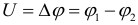
Electric field potential q is the ratio of the potential energy of an electric charge in an electrostatic field to the magnitude of this charge (Volt = 1 J / 1 C).
The work A12 to move an electric charge q from the starting point (1) to the end point (2) is equal to the product of the charge and the potential difference (q1 - c2): A12 = Wp1 - Wp2 = qc1 - qc2 = q(c1 - c2) or
A surface at all points of which the electric field potential has the same values is called an equipotential surface or a surface of equal potential.
Conductors in electrostatic field - E= d/E0. Connection E with density. at almost any conductor. The field strength everywhere inside the conductor must be zero E=0. According to the equation, this means that the potential inside the conductor must be constant, i.e. . Because There is a phenomenon of electrostatic induction, i.e. charge separation in a conductor introduced into an electrostatic field (E external) with the formation of a new electrostatic field (E internal) inside the conductor. When an uncharged conductor is introduced into an external electric field, the free charges begin to move and after a short time come to equilibrium. The field strength on the surface of the conductor must be directed normal to the surface at each point.
Electrostatic protection - Faraday cage, the potential difference can reach millions of volts, but there will be no field inside.

Electrical capacity. Numerically equal to the charge q the message of which to the conductor, meas. its potential by 1. C = q /? c = C / U (F = C / V) The electrical capacity of a conductor does not depend on the type of substance and charge, but depends on its shape and size, as well as on the presence of other conductors or dielectrics nearby. Flat of two conducting plates located parallel to each other at a small distance compared to the size of the plates and separated by a dielectric layer. (ts1-ts2=?Edr =дd/E0, and С=q/?ts, where q=дS => C=E E0S/d)
The parallel (C = C1 + C2) voltages on the capacitors are the same: U1 = U2 = U, and the charges are q1 = C1U and q2 = C2U. Series (C=C1C2/C1+C2) charges of both capacitors: q1 = q2 = q
System energy ac. charge (for 2)
Energy charging conductor, the entire volume of the conductor is equipotential => vosp. previous formula
because C=q/ts then =>
The energy of a charged conductor (regardless of the sign of the charge) is always positive
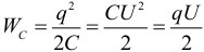
The work done when charging a capacitor will determine its electrical energy. The electrical energy of a charged capacitor is determined by the same formulas that were obtained for a charged conductor, if in them q, C and U respectively determine the charge on the capacitor plates, the capacitance of the capacitor and the potential difference between the capacitor plates. Thus, the energy of a charged capacitor is equal to
Electric field energy. Substituting the expression for capacitance into the formula for capacitor energy gives: The quotient U/d is equal to the field strength in the gap; the product S·d represents the volume V occupied by the field. Hence,
Volumetric energy density. If the field is uniform, then the energy contained in it is distributed in space with a constant density w.
Dielectric materials are those whose main electrical property is the ability to polarize and in which an electrostatic field can exist. A dielectric placed in an external electric field is polarized under the influence of this field. Polarization of a dielectric is the process of acquiring a nonzero macroscopic dipole moment. The molecule turns into a dipole, where el. moment p=ql. Polarization is defined as the electrical moment per unit volume of the dielectric
N is the number of molecules. Relationship between p and density: d=2cosb=Pn
Electric field in a dielectric. Let the electric field strength created by these planes in vacuum be equal. Relationship between polarization and voltage. where diel susceptibility (physical quantity, a measure of the ability of a substance to be polarized under the influence of an electric field) Diel. permeability - abs. (shows the dependence of electrical induction on E). and rel.(e=Сx/C0), [F/m] and dimensionless. respectively. Electrical induction vector D=e0E+P
Polarization electronic theory - displacement of the electron shells of atoms under the influence of an external electric field. Electrical appears. dielectric moment. In non-polar they say Torque = 0, in polar. ex. from 0.
Dipole (Orientation) - occurs with losses in overcoming coupling forces and internal friction. Associated with the orientation of dipoles in an external electric field. -> at air. ext. fields change orientation. molecules created moment
Ionic - displacement of crystal lattice nodes under the influence of an external electric field, and the displacement is by an amount less than the lattice constant.
Ferroelectrics - high (up to 10k) e - isp. in capacitors. Vector D is not proportional to E. D= e e0E. Polar-I segn-depends in large. Art. from the previous state. polarization (dielectric hysteresis loop). Diel. properties depend on the Curie point T, when they disappear (-15 -- +22.5) ... Direct current does not change in magnitude and direction over time.
Current strength is a physical quantity I, equal to the ratio of the amount of charge passing through a certain surface during a time to the value of this period of time. According to Ohm's law for a section of a circuit, I = U/R
Voltage drop is a gradual decrease in voltage along the conductor because the conductor has active resistance. It is also the amount by which the potential changes when moving from one point in the circuit to another. According to Ohm's law, in a section of a conductor with active resistance R, current I creates a voltage drop U=IR.
Resistance is a physical quantity that characterizes the properties of a conductor to prevent the passage of electric current and is equal to the ratio of the voltage at the ends of the conductor to the current flowing through it
Ohm's law in diff. f. ?-ud. electrical conductivity in integration. form JR=U+e e emf for inhomogeneous. chain section:
*R-gen. resistance heterogeneous area) for closed circuit I=e / R+ r e emf r+R total. resistance
Kirchhoff's first rule states that the algebraic sum of the currents in each node of any circuit is equal to zero.
Kirchhoff's second rule: the algebraic sum of the voltage drops on all branches belonging to any closed circuit circuit is equal to the algebraic sum of the EMF of the branches of this circuit.
A magnetic field is created around electric charges as they move. Since the movement of electric charges represents an electric current, there is always a magnetic field of current around any current-carrying conductor.
Doesn't work while stationary. charge.
Pm=ISn mag. contour moment, n position. Normal
Magnetic induction vector B power characteristic mp. Module B = Fmax / Pm.
Biot-Savart-Laplace law Action of mp on currents and charges.
(Strength Amp. F~IДl sin b.max. when the conductor is perpendicular to the lines of magnetic induction) law of interaction of electric currents Ampere's law F=IBDl sin b. When a conductor is introduced into the mp (the force acting on a section of the conductor is proportional to the current strength I, the length Dl of this section and the sine of the angle b between the directions of the current and the magnetic induction vector) For example. gimlet rule. Painting according to the vect of the product. Z.Ampera
Magn. the field acts on each moving charge in the element dl, and from them is transmitted to the conductor.
The Lorentz force is the force with which an electromagnetic field acts on a point charge. particle. FL = q x B sin b. The Lorentz force is directed perpendicular to the vectors n and B.

Vector flux B - characterizes the amount of induction in a given location (value, for example, B = Fmax / Pm), this is the number of lines of force passing through the entire surface. measured in Wb=T m2
Cross the platform. Draw as many lines as the induction in a given place.
Circulation B by closed circuit circuit is equal to the current in the circuit multiplied by the magnetic constant. Bl is the projection of B onto the tangent to the contour.
If con. The current does not cover the circ. = 0. If the several currents, then circ-I is equal to (I+I+…I)m
The lines of magnetic induction are continuous. Vector fields with continuous lines are called vortex fields. The magnetic field is a vortex field. This is the significant difference between a magnetic field and an electrostatic one.
Electromagnetic induction is the phenomenon of the occurrence of electric current (induction) in a closed circuit when the magnetic flux passing through it changes. The occurrence of EMF is associated with vortex electric. field. The magnitude of the EMF responsible for the current (еi):
electric charge induction field
Faraday's law. For any closed loop, the induced electromotive force (EMF) is equal to the rate of change of the magnetic flux passing through this loop, taken with a minus sign
Disadvantage according to Lenz's rule: The induced current is directed so that its magnetic field counteracts the change in the magnetic flux that causes it.
Self-induction is the occurrence of induced emf in a conducting circuit when the current flowing through the circuit changes. When the current in a circuit changes, the magnetic flux through the surface bounded by this circuit also changes proportionally. A change in this magnetic flux, due to the law of electromagnetic induction, leads to the excitation of an inductive emf in this circuit. (..The self-induction current during closure is directed in the opposite direction.)
The magnitude of the self-induction emf Inductance is numerically equal to the self-induction emf that occurs in the conductor when the current strength changes per unit current strength (1 A) per unit time (1 s). 1Gn = 1Vb / 1A
Magnetic energy fields Eddy currents or Foucombe currents are eddy induction currents that arise in conductors when the magnetic field penetrating them changes. Foucault also discovered the phenomenon of heating metal bodies rotated in a magnetic field by eddy currents. In accordance with Lenz's rule, currents choose a direction and path inside a conductor so as to oppose the cause that causes them.
Electromagnetic field is a fundamental physical field that interacts with electrically charged bodies, as well as with bodies that have their own dipole electric and magnetic moments. It is a combination of electric and magnetic fields. Electromagnetic waves are a disturbance of the electromagnetic field propagating in space.
Vortex el. field. Any change in the magnetic field generates an inductive electric field, regardless of the presence or absence of a closed circuit, and if the conductor is open, then a potential difference arises at its ends; If the conductor is closed, then an induced current is observed in it.
Displacement current or absorption current is a quantity directly proportional to the rate of change of electrical induction.
Electrostatics is a branch of the science of electricity that studies stationary electric charges. It is based on 3 main facts: the existence of two types of charges, the presence of interaction between them and the principle of superposition (the interaction of two charges is not affected by the third).
And so in nature there are two types of electric charges. Conventionally, one of them is assigned a plus sign “+” and the other, respectively, a minus sign “-”. There is an electric field around these charges, and if these charges are stationary, then the field is called electrostatic.
Figure 1 Negative and positive charges.
Electric charge is a discrete quantity. That is, it consists of elementary charges of a certain size. And the total charge of any body is a multiple of this elementary charge.
When studying charges in electrostatics, averaging methods are used, both in time and in space. This allows us to consider charges in chaotic thermal motion as stationary.
All charges, both positive and negative, are part of the molecules of a substance. Thus, any body has a large number of charges. But the phenomena of interaction of electrostatic charges can be observed only if the body has an excess (deficiency) of charges of the same sign.
The law of conservation of charge states that if a system is closed, then the total charge in it is unchanged. These charges can be distributed in any way within the system, which will not affect the charge of the system as a whole.
The unit of measurement for the field created by electric charges is intensity. It is depicted graphically in the form of lines of force. The density of the field lines indicates the magnitude of the field strength.

Figure 2 field between unlike charges.
Like charges always repel, and unlike charges attract. Between charges of sizes that can be neglected (point charges), the so-called Coulomb force acts. Coulomb's law determines the force of interaction between two electric charges, depending on their magnitude and the distance between them.

Formula 1 Coulomb's law
The electrostatic field is potential. This means that the work done to move a charge from one point to another does not depend on the shape of the charge path. If one of the points is at infinity, then the concept of electric potential can be introduced. It determines the work spent on moving a charge from infinity to a given point in space.
And finally, let's talk about the principle of field superposition. The essence of the principle is that the resulting field of several point charges will be the vector sum of the fields of each of the charges separately. That is, the field of the third charge does not affect the fields of the other two charges.

Figure 3 principle of field superposition
The main problems that electrostatics solves are determining the charge distribution over a surface, knowing the potential of the surface or its total charge. Finding the energy of a system of conductors, knowing their charges and potentials. And also the study of the behavior of various substances in an electric field.
Encyclopedic YouTube
-
1 / 5
The foundation of electrostatics was laid by the work of Coulomb (although ten years before him, the same results, even with even greater accuracy, were obtained by Cavendish. The results of Cavendish’s work were kept in the family archive and were published only a hundred years later); the law of electrical interactions discovered by the latter made it possible for Green, Gauss and Poisson to create a mathematically elegant theory. The most essential part of electrostatics is the theory of potential, created by Green and Gauss. A lot of experimental research on electrostatics was carried out by Rees, whose books in the past constituted the main guide for the study of these phenomena.
The dielectric constant
Finding the value of the dielectric coefficient K of any substance, a coefficient included in almost all formulas that one has to deal with in electrostatics, can be done in very different ways. The most commonly used methods are the following.
1) Comparison of the electrical capacitances of two capacitors having the same size and shape, but in one of which the insulating layer is a layer of air, in the other - a layer of the dielectric being tested.
2) Comparison of attractions between the surfaces of a capacitor, when a certain potential difference is imparted to these surfaces, but in one case there is air between them (attractive force = F 0), in the other case, the test liquid insulator (attractive force = F). The dielectric coefficient is found by the formula:
K = F 0 F . (\displaystyle K=(\frac (F_(0))(F)).)3) Observations of electric waves (see Electrical oscillations) propagating along wires. According to Maxwell's theory, the speed of propagation of electric waves along wires is expressed by the formula
V = 1 K μ . (\displaystyle V=(\frac (1)(\sqrt (K\mu ))).)in which K denotes the dielectric coefficient of the medium surrounding the wire, μ denotes the magnetic permeability of this medium. We can put μ = 1 for the vast majority of bodies, and therefore it turns out
V = 1 K. (\displaystyle V=(\frac (1)(\sqrt (K))).)Usually, the lengths of standing electric waves that arise in parts of the same wire located in the air and in the test dielectric (liquid) are compared. Having determined these lengths λ 0 and λ, we obtain K = λ 0 2 / λ 2. According to Maxwell’s theory, it follows that when an electric field is excited in any insulating substance, special deformations occur inside this substance. Along the induction tubes, the insulating medium is polarized. Electrical displacements arise in it, which can be likened to the movements of positive electricity in the direction of the axes of these tubes, and through each cross section of the tube passes an amount of electricity equal to
D = 1 4 π K F . (\displaystyle D=(\frac (1)(4\pi ))KF.)Maxwell's theory makes it possible to find expressions for those internal forces (forces of tension and pressure) that appear in dielectrics when an electric field is excited in them. This question was first considered by Maxwell himself, and later in more detail by Helmholtz. Further development of the theory of this issue and the closely connected theory of electrostriction (that is, the theory that considers phenomena that depend on the occurrence of special voltages in dielectrics when an electric field is excited in them) belongs to the works of Lorberg, Kirchhoff, P. Duhem, N. N. Schiller and some others
Border conditions
Let us complete our brief presentation of the most significant aspects of electrostriction by considering the issue of refraction of induction tubes. Let us imagine two dielectrics in an electric field, separated from each other by some surface S, with dielectric coefficients K 1 and K 2.
Let at points P 1 and P 2 located infinitely close to the surface S on either side of it, the magnitudes of the potentials are expressed through V 1 and V 2 , and the magnitudes of the forces experienced by a unit of positive electricity placed at these points through F 1 and F 2. Then for a point P lying on the surface S itself, there must be V 1 = V 2,
d V 1 d s = d V 2 d s , (30) (\displaystyle (\frac (dV_(1))(ds))=(\frac (dV_(2))(ds)),\qquad (30))if ds represents an infinitesimal displacement along the line of intersection of the tangent plane to the surface S at point P with the plane passing through the normal to the surface at this point and through the direction of the electric force in it. On the other hand, it should be
K 1 d V 1 d n 1 + K 2 d V 2 d n 2 = 0. (31) (\displaystyle K_(1)(\frac (dV_(1))(dn_(1)))+K_(2)( \frac (dV_(2))(dn_(2)))=0.\qquad (31))Let us denote by ε 2 the angle made by the force F2 with the normal n2 (inside the second dielectric), and by ε 1 the angle made by the force F 1 with the same normal n 2 Then, using formulas (31) and (30), we find
t g ε 1 t g ε 2 = K 1 K 2 . (\displaystyle (\frac (\mathrm (tg) (\varepsilon _(1)))(\mathrm (tg) (\varepsilon _(2))))=(\frac (K_(1))(K_( 2))).)So, on the surface separating two dielectrics from each other, the electric force undergoes a change in its direction, like a light ray entering from one medium into another. This consequence of the theory is justified by experience.
Electric charge is a physical quantity that characterizes the ability of particles or bodies to enter into electromagnetic interactions. Electric charge is usually represented by the letters q or Q. In the SI system, electric charge is measured in Coulombs (C). A free charge of 1 C is a gigantic amount of charge, practically not found in nature. Typically, you will have to deal with microcoulombs (1 µC = 10 -6 C), nanocoulombs (1 nC = 10 -9 C) and picoculombs (1 pC = 10 -12 C). Electric charge has the following properties:
1. Electric charge is a type of matter.
2. The electric charge does not depend on the movement of the particle and its speed.
3. Charges can be transferred (for example, by direct contact) from one body to another. Unlike body mass, electric charge is not an integral characteristic of a given body. The same body under different conditions can have a different charge.
4. There are two types of electric charges, conventionally called positive And negative.
5. All charges interact with each other. In this case, like charges repel, unlike charges attract. The forces of interaction between charges are central, that is, they lie on a straight line connecting the centers of the charges.
6. There is a minimum possible (modulo) electric charge, called elementary charge. Its meaning:
e= 1.602177·10 –19 C ≈ 1.6·10 –19 C.
The electric charge of any body is always a multiple of the elementary charge:
Where: N– an integer. Please note that it is impossible for a charge equal to 0.5 to exist e; 1,7e; 22,7e and so on. Physical quantities that can only take a discrete (not continuous) series of values are called quantized. Elementary charge e is a quantum (smallest portion) of electric charge.
In an isolated system, the algebraic sum of the charges of all bodies remains constant:
The law of conservation of electric charge states that in a closed system of bodies processes of creation or disappearance of charges of only one sign cannot be observed. It also follows from the law of conservation of charge that if two bodies of the same size and shape having charges q 1 and q 2 (it doesn’t matter at all what sign the charges are), bring into contact, and then separate again, then the charge of each of the bodies will become equal:
From a modern point of view, charge carriers are elementary particles. All ordinary bodies consist of atoms, which include positively charged protons, negatively charged electrons and neutral particles - neutrons. Protons and neutrons are part of atomic nuclei, electrons form the electron shell of atoms. The electric charges of a proton and an electron are exactly the same in absolute value and equal to the elementary (that is, the minimum possible) charge e.
In a neutral atom, the number of protons in the nucleus is equal to the number of electrons in the shell. This number is called the atomic number. An atom of a given substance may lose one or more electrons, or gain an extra electron. In these cases, the neutral atom turns into a positively or negatively charged ion. Please note that positive protons are part of the nucleus of an atom, so their number can only change during nuclear reactions. It is obvious that when bodies are electrified, nuclear reactions do not occur. Therefore, in any electrical phenomena, the number of protons does not change, only the number of electrons changes. Thus, imparting a negative charge to a body means transferring extra electrons to it. And the message of a positive charge, contrary to a common mistake, does not mean the addition of protons, but the subtraction of electrons. Charge can be transferred from one body to another only in portions containing an integer number of electrons.
Sometimes in problems the electric charge is distributed over a certain body. To describe this distribution, the following quantities are introduced:
1. Linear charge density. Used to describe the distribution of charge along the filament:
Where: L– thread length. Measured in C/m.
2. Surface charge density. Used to describe the distribution of charge over the surface of a body:
Where: S– body surface area. Measured in C/m2.
3. Volume charge density. Used to describe the distribution of charge over the volume of a body:
Where: V– body volume. Measured in C/m3.
Please note that electron mass is equal to:
m e= 9.11∙10 –31 kg.
Coulomb's law
Point charge called a charged body, the dimensions of which can be neglected in the conditions of this problem. Based on numerous experiments, Coulomb established the following law:
The interaction forces between stationary point charges are directly proportional to the product of the charge moduli and inversely proportional to the square of the distance between them:
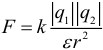
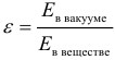
Where: ε – dielectric constant of a medium is a dimensionless physical quantity that shows how many times the force of electrostatic interaction in a given medium will be less than in a vacuum (that is, how many times the medium weakens the interaction). Here k– coefficient in Coulomb’s law, a value that determines the numerical value of the force of interaction of charges. In the SI system its value is taken equal to:
k= 9∙10 9 m/F.
The forces of interaction between point fixed charges obey Newton's third law, and are forces of repulsion from each other with the same signs of charges and forces of attraction to each other with different signs. The interaction of stationary electric charges is called electrostatic or Coulomb interaction. The branch of electrodynamics that studies the Coulomb interaction is called electrostatics.
Coulomb's law is valid for point charged bodies, uniformly charged spheres and balls. In this case, for distances r take the distance between the centers of spheres or balls. In practice, Coulomb's law is well satisfied if the sizes of charged bodies are much smaller than the distance between them. Coefficient k in the SI system it is sometimes written as:

Where: ε 0 = 8.85∙10 –12 F/m – electrical constant.
Experience shows that the forces of Coulomb interaction obey the principle of superposition: if a charged body interacts simultaneously with several charged bodies, then the resulting force acting on this body is equal to the vector sum of the forces acting on this body from all other charged bodies.
Remember also two important definitions:
Conductors– substances containing free electric charge carriers. Inside a conductor, free movement of electrons - charge carriers - is possible (electric current can flow through the conductors). Conductors include metals, solutions and melts of electrolytes, ionized gases, and plasma.
Dielectrics (insulators)– substances in which there are no free charge carriers. The free movement of electrons inside dielectrics is impossible (electric current cannot flow through them). It is dielectrics that have a certain dielectric constant, not equal to unity. ε .
For the dielectric constant of a substance, the following is true (about what an electric field is just below):
Electric field and its intensity
According to modern concepts, electric charges do not act on each other directly. Each charged body creates in the surrounding space electric field. This field exerts a force on other charged bodies. The main property of the electric field is the effect on electric charges with some force. Thus, the interaction of charged bodies is carried out not by their direct influence on each other, but through the electric fields surrounding the charged bodies.
The electric field surrounding a charged body can be studied using a so-called test charge - a small point charge that does not introduce a noticeable redistribution of the charges being studied. To quantitatively determine the electric field, a force characteristic is introduced - electric field strength E.
Electric field strength is a physical quantity equal to the ratio of the force with which the field acts on a test charge placed at a given point in the field to the magnitude of this charge:

Electric field strength is a vector physical quantity. The direction of the tension vector coincides at each point in space with the direction of the force acting on the positive test charge. The electric field of stationary charges that do not change over time is called electrostatic.
To visually represent the electric field, use power lines. These lines are drawn so that the direction of the tension vector at each point coincides with the direction of the tangent to the line of force. Field lines have the following properties.
- Electrostatic field lines never intersect.
- The electrostatic field lines are always directed from positive to negative charges.
- When depicting an electric field using field lines, their density should be proportional to the magnitude of the field strength vector.
- Lines of force begin at a positive charge, or infinity, and end at a negative charge, or infinity. The greater the tension, the greater the density of the lines.
- At a given point in space, only one line of force can pass, because The electric field strength at a given point in space is specified uniquely.
An electric field is called uniform if the intensity vector is the same at all points of the field. For example, a uniform field is created by a flat capacitor - two plates charged with a charge of equal magnitude and opposite sign, separated by a dielectric layer, and the distance between the plates is much less than the size of the plates.
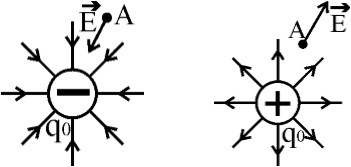
At all points of a uniform field on a charge q, introduced into a uniform field with intensity E, a force of equal magnitude and direction acts, equal to F = Eq. Moreover, if the charge q positive, then the direction of the force coincides with the direction of the tension vector, and if the charge is negative, then the force and tension vectors are oppositely directed.
Positive and negative point charges are shown in the figure:
Superposition principle
If an electric field created by several charged bodies is studied using a test charge, then the resulting force turns out to be equal to the geometric sum of the forces acting on the test charge from each charged body separately. Consequently, the electric field strength created by a system of charges at a given point in space is equal to the vector sum of the electric field strengths created at the same point by charges separately:
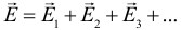
This property of the electric field means that the field obeys superposition principle. In accordance with Coulomb's law, the strength of the electrostatic field created by a point charge Q on distance r from it, is equal in modulus:

This field is called Coulomb field. In a Coulomb field, the direction of the intensity vector depends on the sign of the charge Q: If Q> 0, then the voltage vector is directed away from the charge, if Q < 0, то вектор напряженности направлен к заряду. Величина напряжённости зависит от величины заряда, среды, в которой находится заряд, и уменьшается с увеличением расстояния.
The electric field strength created by a charged plane near its surface:
So, if the problem requires determining the field strength of a system of charges, then we must proceed as follows algorithm:
- Draw a picture.
- Draw the field strength of each charge separately at the desired point. Remember that tension is directed towards a negative charge and away from a positive charge.
- Calculate each of the tensions using the appropriate formula.
- Add the stress vectors geometrically (i.e. vectorially).
Potential energy of charge interaction
Electric charges interact with each other and with the electric field. Any interaction is described by potential energy. Potential energy of interaction of two point electric charges calculated by the formula:
Please note that the charges have no modules. For unlike charges, the interaction energy has a negative value. The same formula is valid for the interaction energy of uniformly charged spheres and balls. As usual, in this case the distance r is measured between the centers of the balls or spheres. If there are not two, but more charges, then the energy of their interaction should be calculated as follows: divide the system of charges into all possible pairs, calculate the interaction energy of each pair and sum up all the energies for all pairs.
Problems on this topic are solved, like problems on the law of conservation of mechanical energy: first, the initial energy of interaction is found, then the final one. If the problem asks you to find the work done to move charges, then it will be equal to the difference between the initial and final total energy of interaction of charges. Interaction energy can also be converted into kinetic energy or other types of energy. If the bodies are at a very large distance, then the energy of their interaction is assumed to be equal to 0.
Please note: if the problem requires finding the minimum or maximum distance between bodies (particles) when moving, then this condition will be met at that moment in time when the particles move in one direction at the same speed. Therefore, the solution must begin by writing down the law of conservation of momentum, from which this identical speed is found. And then we should write the law of conservation of energy, taking into account the kinetic energy of particles in the second case.
Potential. Potential difference. Voltage
The electrostatic field has an important property: the work of the electrostatic field forces when moving a charge from one point in the field to another does not depend on the shape of the trajectory, but is determined only by the position of the starting and ending points and the magnitude of the charge.
A consequence of the independence of work from the shape of the trajectory is the following statement: the work of electrostatic field forces when moving a charge along any closed trajectory is equal to zero.
The property of potentiality (independence of work from the shape of the trajectory) of the electrostatic field allows us to introduce the concept of potential energy of a charge in an electric field. And a physical quantity equal to the ratio of the potential energy of an electric charge in an electrostatic field to the magnitude of this charge is called potential φ electric field:
Potential φ is the energy characteristic of the electrostatic field. In the International System of Units (SI), the unit of potential (and therefore potential difference, i.e. voltage) is the volt [V]. Potential is a scalar quantity.
In many problems of electrostatics, when calculating potentials, it is convenient to take the point at infinity as the reference point where the values of potential energy and potential vanish. In this case, the concept of potential can be defined as follows: the field potential at a given point in space is equal to the work done by electric forces when removing a single positive charge from a given point to infinity.
Recalling the formula for the potential energy of interaction of two point charges and dividing it by the value of one of the charges in accordance with the definition of potential, we obtain that potential φ point charge fields Q on distance r from it relative to a point at infinity is calculated as follows:
The potential calculated using this formula can be positive or negative depending on the sign of the charge that created it. The same formula expresses the field potential of a uniformly charged ball (or sphere) at r ≥ R(outside the ball or sphere), where R is the radius of the ball, and the distance r measured from the center of the ball.
To visually represent the electric field, along with field lines, use equipotential surfaces. A surface at all points of which the electric field potential has the same values is called an equipotential surface or a surface of equal potential. Electric field lines are always perpendicular to equipotential surfaces. The equipotential surfaces of the Coulomb field of a point charge are concentric spheres.
Electrical voltage it's just a potential difference, i.e. The definition of electrical voltage can be given by the formula:
In a uniform electric field there is a relationship between field strength and voltage:
Electric field work can be calculated as the difference between the initial and final potential energy of a system of charges:
The work of the electric field in the general case can also be calculated using one of the formulas:
In a uniform field, when a charge moves along its field lines, the work of the field can also be calculated using the following formula:
In these formulas:
- φ – electric field potential.
- ∆φ – potential difference.
- W– potential energy of a charge in an external electric field.
- A– the work of the electric field to move the charge (charges).
- q– a charge that moves in an external electric field.
- U- voltage.
- E– electric field strength.
- d or ∆ l– the distance to which the charge is moved along the lines of force.
In all previous formulas we were talking specifically about the work of the electrostatic field, but if the problem says that “work must be done”, or we are talking about “the work of external forces”, then this work should be considered in the same way as the work of the field, but with opposite sign.
Potential superposition principle
From the principle of superposition of field strengths created by electric charges, the principle of superposition for potentials follows (in this case, the sign of the field potential depends on the sign of the charge that created the field):
Notice how much easier it is to apply the principle of superposition of potential than of tension. Potential is a scalar quantity that has no direction. Adding potentials is simply adding up numerical values.
Electrical capacity. Flat capacitor
When imparting a charge to a conductor, there is always a certain limit beyond which it will not be possible to charge the body. To characterize the ability of a body to accumulate electric charge, the concept is introduced electrical capacitance. The capacitance of an isolated conductor is the ratio of its charge to potential:
In the SI system, capacitance is measured in Farads [F]. 1 Farad is an extremely large capacitance. For comparison, the capacitance of the entire globe is significantly less than one farad. The capacitance of a conductor depends neither on its charge nor on the potential of the body. Similarly, density does not depend on either the mass or volume of the body. Capacity depends only on the shape of the body, its size and the properties of its environment.
Electric capacity system of two conductors is a physical quantity defined as the ratio of charge q one of the conductors to the potential difference Δ φ between them:

The magnitude of the electrical capacitance of conductors depends on the shape and size of the conductors and on the properties of the dielectric separating the conductors. There are configurations of conductors in which the electric field is concentrated (localized) only in a certain region of space. Such systems are called capacitors, and the conductors that make up the capacitor are called linings.
The simplest capacitor is a system of two flat conducting plates located parallel to each other at a small distance compared to the size of the plates and separated by a dielectric layer. Such a capacitor is called flat. The electric field of a parallel-plate capacitor is mainly localized between the plates.
Each of the charged plates of a flat capacitor creates an electric field near its surface, the modulus of which is expressed by the relationship already given above. Then the modulus of the final field strength inside the capacitor created by the two plates is equal to:

Outside the capacitor, the electric fields of the two plates are directed in different directions, and therefore the resulting electrostatic field E= 0. can be calculated using the formula:
Thus, the electrical capacity of a flat capacitor is directly proportional to the area of the plates (plates) and inversely proportional to the distance between them. If the space between the plates is filled with a dielectric, the capacitance of the capacitor increases by ε once. note that S in this formula there is the area of only one capacitor plate. When they talk about the “plating area” in a problem, they mean exactly this value. You never need to multiply or divide it by 2.
Once again we present the formula for capacitor charge. The charge of a capacitor is understood only as the charge on its positive plate:
The force of attraction between the capacitor plates. The force acting on each plate is determined not by the total field of the capacitor, but by the field created by the opposite plate (the plate does not act on itself). The strength of this field is equal to half the strength of the total field, and the force of interaction between the plates is:
Capacitor energy. It is also called the energy of the electric field inside the capacitor. Experience shows that a charged capacitor contains a reserve of energy. The energy of a charged capacitor is equal to the work of external forces that must be expended to charge the capacitor. There are three equivalent forms of writing the formula for the energy of a capacitor (they follow one from the other if we use the relation q = C.U.):
Pay special attention to the phrase: “The capacitor is connected to the source.” This means that the voltage across the capacitor does not change. And the phrase “The capacitor was charged and disconnected from the source” means that the charge of the capacitor will not change.
Electric field energy
Electrical energy should be considered as potential energy stored in a charged capacitor. According to modern concepts, the electrical energy of a capacitor is localized in the space between the plates of the capacitor, that is, in the electric field. Therefore it is called electric field energy. The energy of charged bodies is concentrated in space in which there is an electric field, i.e. we can talk about the energy of the electric field. For example, a capacitor's energy is concentrated in the space between its plates. Thus, it makes sense to introduce a new physical characteristic - the volumetric energy density of the electric field. Using a flat capacitor as an example, we can obtain the following formula for the volumetric energy density (or the energy per unit volume of the electric field):
Capacitor connections
Parallel connection of capacitors– to increase capacity. The capacitors are connected by similarly charged plates, as if increasing the area of the equally charged plates. The voltage on all capacitors is the same, the total charge is equal to the sum of the charges of each capacitor, and the total capacitance is also equal to the sum of the capacitances of all capacitors connected in parallel. Let's write down the formulas for parallel connection of capacitors:
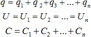
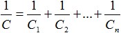
At series connection of capacitors the total capacity of a capacitor bank is always less than the capacity of the smallest capacitor included in the battery. A series connection is used to increase the breakdown voltage of the capacitors. Let's write down the formulas for connecting capacitors in series. The total capacitance of series-connected capacitors is found from the relationship:
From the law of conservation of charge it follows that the charges on adjacent plates are equal:
The voltage is equal to the sum of the voltages on the individual capacitors.
For two capacitors connected in series, the formula above will give us the following expression for the total capacitance:
For N identical series-connected capacitors:
Conductive sphere
The field strength inside a charged conductor is zero. Otherwise, an electric force would act on the free charges inside the conductor, which would force these charges to move inside the conductor. This movement, in turn, would lead to heating of the charged conductor, which actually does not happen.
The fact that there is no electric field inside the conductor can be understood in another way: if there was one, then the charged particles would again move, and they would move exactly in such a way as to reduce this field to zero with their own field, because in fact, they would not want to move, because every system strives for balance. Sooner or later, all moving charges would stop exactly in that place so that the field inside the conductor would become zero.
On the surface of the conductor, the electric field strength is maximum. The magnitude of the electric field strength of a charged ball outside its boundaries decreases with distance from the conductor and is calculated using a formula similar to the formula for the field strength of a point charge, in which distances are measured from the center of the ball.
Since the field strength inside a charged conductor is zero, the potential at all points inside and on the surface of the conductor is the same (only in this case the potential difference, and therefore the voltage, is zero). The potential inside a charged ball is equal to the potential on the surface. The potential outside the ball is calculated using a formula similar to the formulas for the potential of a point charge, in which distances are measured from the center of the ball.
Radius R:
If the ball is surrounded by a dielectric, then:
Properties of a conductor in an electric field
- Inside a conductor, the field strength is always zero.
- The potential inside the conductor is the same at all points and is equal to the potential of the surface of the conductor. When they say in a problem that “the conductor is charged to a potential ... V,” they mean precisely the surface potential.
- Outside the conductor near its surface, the field strength is always perpendicular to the surface.
- If a charge is given to a conductor, then it will all be distributed over a very thin layer near the surface of the conductor (usually they say that the entire charge of the conductor is distributed on its surface). This is easily explained: the fact is that when imparting a charge to a body, we transfer to it charge carriers of the same sign, i.e. like charges that repel each other. This means they will try to run away from each other to the maximum possible distance, i.e. accumulate at the very edges of the conductor. As a result, if the core is removed from a conductor, its electrostatic properties will not change in any way.
- Outside the conductor, the more curved the surface of the conductor, the greater the field strength. The maximum value of tension is achieved near the edges and sharp breaks in the surface of the conductor.
Notes on solving complex problems
1. Grounding something means the connection of a conductor of this object with the Earth. In this case, the potentials of the Earth and the existing object are equalized, and the charges necessary for this move along the conductor from the Earth to the object or vice versa. In this case, it is necessary to take into account several factors that follow from the fact that the Earth is disproportionately larger than any object located on it:
- The total charge of the Earth is conventionally zero, so its potential is also zero, and it will remain zero after the object connects with the Earth. In a word, to ground means to reset the potential of an object.
- To reset the potential (and therefore the object’s own charge, which could previously have been either positive or negative), the object will have to either accept or give to the Earth some (perhaps even a very large) charge, and the Earth will always be able to provide this possibility.
2. Let us repeat once again: the distance between repelling bodies is minimal at the moment when their velocities become equal in magnitude and directed in the same direction (the relative speed of the charges is zero). At this moment, the potential energy of interaction of charges is maximum. The distance between attracting bodies is maximum, also at the moment of equality of velocities directed in one direction.
3. If the problem involves a system consisting of a large number of charges, then it is necessary to consider and describe the forces acting on a charge that is not located at the center of symmetry.
- Learn all the formulas and laws in physics, and formulas and methods in mathematics. In fact, this is also very simple to do; there are only about 200 necessary formulas in physics, and even a little less in mathematics. In each of these subjects there are about a dozen standard methods for solving problems of a basic level of complexity, which can also be learned, and thus, completely automatically and without difficulty solving most of the CT at the right time. After this, you will only have to think about the most difficult tasks.
- Attend all three stages of rehearsal testing in physics and mathematics. Each RT can be visited twice to decide on both options. Again, on the CT, in addition to the ability to quickly and efficiently solve problems, and knowledge of formulas and methods, you must also be able to properly plan time, distribute forces, and most importantly, correctly fill out the answer form, without confusing the numbers of answers and problems, or your own last name. Also, during RT, it is important to get used to the style of asking questions in problems, which may seem very unusual to an unprepared person at the DT.
Successful, diligent and responsible implementation of these three points will allow you to show an excellent result at the CT, the maximum of what you are capable of.
Found a mistake?
If you think you have found an error in the training materials, please write about it by email. You can also report an error on the social network (). In the letter, indicate the subject (physics or mathematics), the name or number of the topic or test, the number of the problem, or the place in the text (page) where, in your opinion, there is an error. Also describe what the suspected error is. Your letter will not go unnoticed, the error will either be corrected, or you will be explained why it is not an error.
 (1 ratings, on average: 5,00 out of 5)