Pinout of mini hdmi connector by color. HDMI cable pinout
The HDMI cable's structure resembles the well-known " twisted pair", but it only consists of a larger number of cores - 19. Knowing the cable pinout diagram, you can connect an HDMI socket or repair a damaged connector.
Many may ask: why repair a damaged HDMI cable or its connector? After all, it’s easier to buy a new wire, since the prices for it are now more than affordable. For example, a 5 meter HDMI cable can be purchased for around 500 rubles. And he will match everyone modern standards: High Speed with Ethernet, support 3D and 4K.
We answer: What if the cable is embedded in a wall or corrugation and there is no way to simply pull it out and replace it? Or are you a connoisseur of top Hi-End brands and you use only premium HDMI cables, the cost of which starts at several thousand rubles per 1 meter?!
In this case, you can significantly save on purchasing a new cable by replacing the damaged HDMI connector.
So, without going into technical details, let's look at the pinout of any modern HDMI cable(High Speed with Ethernet class).
Pinout of HDMI connector Type A (19pin)

HDMI cable pinout from inside
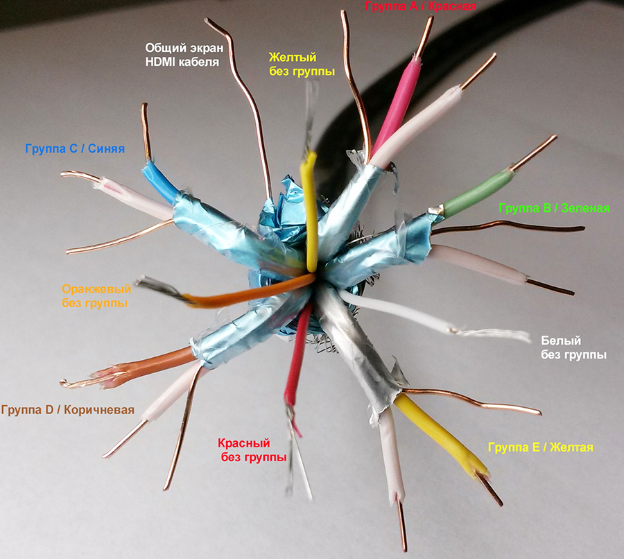
As you can see, the HDMI cable is divided into 5 groups of 3 cores. And 4 more wires go separately (not grouped).

United color coding There are no cores, and each cable manufacturer may have its own marking. Our HDMI cable used the following:

Let's try it with an example of this cable, which is sold sliced (there are some), demonstrate its cutting and finishing.
HDMI cable cutting
1. Strip the HDMI cable from the outer sheath.

2. Move the screen braid and release the groups of wires.

3. We form groups of contacts and clear them.
4. As a connector to the cable, we will use the Dr.HD HDMI socket module for crimping.


This module is convenient because you can terminate an HDMI cable yourself without a special set of expensive crimping equipment. And by placing it in a frame, you will have a full-fledged HDMI socket.
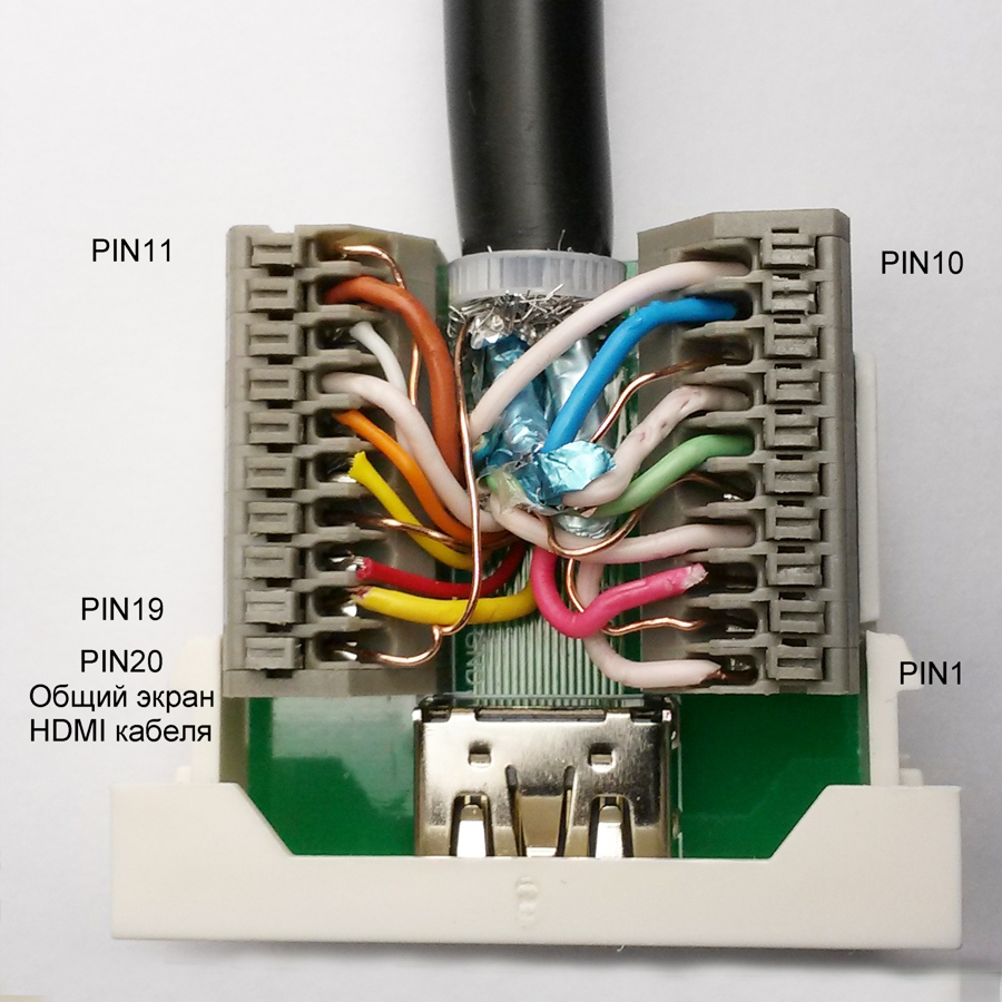
5. According to the table, we clamp each wire into the terminal blocks of the module.
Thus, during renovation or construction, you can install an HDMI cable of the required length into the wall. End it on both sides with a Dr.HD HDMI socket module for crimping.


Let's consider the case when the HDMI cable connector is broken.

We act on the same points.
1. We strip the cable, release and form groups of wires.

2. Since the cross-section of the cores here is smaller and the wire is stranded, they will require tinning.
To find out which of the groups is A/B/C/D/E, you will need a tester (continuity). Only after you have determined the correct grouping of wires, as well as four wires without a group, can you begin crimping.

We have successfully tested the operation of this refurbished cable. The source was a Blue-Ray drive and a 3D video. We did not see any digital interference.
Introduction
In 2002 large manufacturers consumer electronics, including Hitachi, Philips, Sony, Toshiba and others, offered new interface High-Definition Multimedia Interface (HDMI). It was the first fully digital interface for transmitting uncompressed audio and video streams, while being backward compatible with DVI, which transmits digital video streams.
The HDMI interface has constantly evolved. Today there are already several versions with different numbers. The first version of HDMI 1.0 appeared back in 2002. The most recent HDMI 1.3 was approved in June 2006. Each version uses the same hardware specifications and cable, but differs in increased throughput and types of information that can be transmitted via HDMI. For example, HDMI 1.0 supports maximum speed 4.9 Gbit/s, and HDMI 1.3 is already 10.2 Gbit/s.
Below is brief information about HDMI versions.
- HDMI 1.0 - 12/2002.
- One cable for transmitting digital audio/video streams with a maximum throughput of 4.9 Gbps. Supports video streams up to 165 megapixels per second (1080p @ 60 Hz or UXGA) and 8-channel 192 kHz/24-bit audio.
- HDMI 1.1 - 5/2004.
- Added support for protecting DVD Audio content.
- HDMI 1.2 - 8/2005.
- Added support for Super Audio CD;
- HDMI Type A connector for connecting a PC as a source;
- PC sources can use native RGB color mode, retaining the YCbCr color mode option;
- support for low voltage sources.
- HDMI 1.3 - 6/2006.
- Audio/video connection capacity has been increased to 10.2 Gbps;
- improved color support, including 30, 36 and 48 bit depth (RGB or YCbCr);
- added support for xvYCC color standards;
- added support for automatic audio synchronization;
- added support for Dolby TrueHD and DTS-HD streams (formats used in HD DVD and Blu-ray discs) for decoding by external receivers;
- a new mini-jack was approved for devices such as video cameras.
Below is a table of the main improvements in version 1.3 compared to 1.2.
| Function | HDMI 1.2 | HDMI 1.3 |
| Maximum throughput | 4.95 Gbps | 10.2 Gbps |
| Maximum frequency band | 165 MHz | 340 MHz |
| Maximum resolution | 1920x1080 progressive (1080p) | 2560x1440 progressive (1440p) |
| Maximum color depth | 24 bits | 48 bit |
| Maximum number of colors | 16.7 million | 281 trillion |
| DTS and Dolby Digital 5.1 support | Yes | Yes |
| Dolby TrueHD and DTS-HD support | No | Yes |
| Maximum audio sampling rate (2 channels) | 192 kHz | 768 kHz |
| Maximum audio sampling rate (3 to 8 channels) | 96 kHz (4 streams max.) | 192 kHz (8 streams max.) |
Technical information
Below is the HDMI interface diagram.
Pin 1 - TMDS Data2+
Pin 2 - TMDS Data2 Shield
Pin 3 - TMDS Data2-
Pin 4 - TMDS Data1+
Pin 5 - TMDS Data1 Shield
Pin 6 - TMDS Data1-
Pin 7 - TMDS Data0+
Pin 8 - TMDS Data0 Shield
Pin 9 - TMDS Data0-
Pin 10 - TMDS Clock+
Pin 11 - TMDS Clock Shield
Pin 12 - TMDS Clock-
Pin 13 - CEC
Pin 14 -Reserved (N.C. on device)
Pin 15 - SCL
Pin 16 - SDA
Pin 17 - DDC/CEC Ground
Pin 18 - +5 V Power
Pin 19 - Hot Plug Detect
- TMDS (Transition-Minimized Differential Signaling). High-speed digital stream technology used in HDMI interfaces and DVI. Uses three channels transmitting audio/video and additional data streams, with a throughput of up to 3.4 Gbps per channel.
- CEC (Consumer Electronics Control). Allows you to transmit commands and control signals between communication participants. CEC functions are built in at the manufacturer's discretion. If all communication participants support HDMI CEC, then you will be able, for example, to send commands from the remote control to all connected equipment. Commands include on/off, playback, standby, recording and others.
- SCL (Serial Data Clock). Responsible for synchronizing data transfer.
- SDA (Serial Data Access). Transfers data.
- DDC (Display Data Channel). Allows you to transfer display specifications such as manufacturer name, model number, supported formats and resolutions, etc.
Format support
Today all major video formats are supported, including PAL, NTSC, ATSC and others. Video resolution is possible up to 1440p or 2560x1440 in progressive format (for Blu-ray and HD-DVD it is a maximum of 1080p). Supports color depth up to 48 bits (more than 280 trillion colors) with a refresh rate of up to 120 Hz.
An HDMI cable in its structure resembles the well-known “twisted pair”, but it only consists of a larger number of cores - 19. Knowing the cable pinout diagram, you can connect an HDMI socket or repair a damaged connector.
Many may ask: why repair a damaged HDMI cable or its connector? After all, it’s easier to buy a new wire, since the prices for it are now more than affordable. For example, you can purchase within 1000 rubles. And it will meet all modern standards: High Speed with Ethernet, support for 3D and 4K.
We answer: What if the cable is embedded in a wall or corrugation and there is no way to simply pull it out and replace it? Or are you a connoisseur of top Hi-End brands and you use only premium HDMI cables, the cost of which starts at several thousand rubles per 1 meter?!
In this case, you can significantly save on purchasing a new cable by replacing the damaged HDMI connector.
So, without going into technical details, let’s look at the pinout of any modern HDMI cable (High Speed with Ethernet class).
Pinout of HDMI connector Type A (19pin)
HDMI cable pinout from inside
As you can see, the HDMI cable is divided into 5 groups of 3 cores. And 4 more wires go separately (not grouped).
There is no single color marking for cores, and each cable manufacturer may have its own marking. Our HDMI cable used the following:

Let's try using the example of this cable, which is sold pre-cut (there are some), to demonstrate its cutting and termination.
HDMI cable cutting
1. Strip the HDMI cable from the outer sheath.
2. Move the screen braid and release the groups of wires.
3. We form groups of contacts and clear them.
4. We will use a socket module as a connector to the cable.
This module is convenient because you can terminate an HDMI cable yourself without a special set of expensive crimping equipment. And by placing it in a frame, you will have a full-fledged HDMI socket.
5. According to the table, we clamp each wire into the terminal blocks of the module.
Thus, during renovation or construction, you can install an HDMI cable of the required length into the wall. End it on both sides with a Dr.HD HDMI socket module for crimping.
Let's consider the case when the HDMI cable connector is broken.
We act on the same points.
1. We strip the cable, release and form groups of wires.
2. Since the cross-section of the cores here is smaller and the wire is stranded, they will require tinning.
To find out which of the groups is A/B/C/D/E, you will need a tester (continuity). Only after you have determined the correct grouping of wires, as well as four wires without a group, can you begin crimping.
We have successfully tested the operation of this refurbished cable. The source was a Blue-Ray drive and a 3D video. We did not see any digital interference.
That's all!
Fri, 2015-04-10 13:39
 (1 ratings, on average: 5,00 out of 5)