Homemade radio from a car radio. How to make a music center from a radio. Electrical connection diagram
Music is something that many people cannot give up, either at home, on vacation, or even while driving a car. And everyone knows what is needed for music! No, we are not talking about instruments, orchestras and performers, we are primarily about devices that are able to reproduce it. This is what we have at home music Center, in nature there is a portable radio tape recorder, and in the car there is a radio tape recorder. What to do if you have a car radio and need to listen to music at home? In fact, a car radio is quite capable of replacing a music center; here you just need to supply power to it, connect the acoustics, and also think about the case. It is this option for upgrading a car radio, when you can turn it into a music center, that we will talk about in our article.
What to take as a basis for a music center from a car radio

So, we roughly know what we need:
Power unit;
- acoustics;
- frame.
...so how can we try to implement all this with minimal costs? If you look around and take a closer look, you can find things that meet our requirements in almost all respects, while the investment in them is minimal. For example, an old system unit, if you remove all the already “used internals” from it and provided that it has a working power supply, then it’s simple perfect option for our case. We will continue our story about how to make a music center from an old computer system unit and car radio.
The process of making a music center from a car radio and a system unit with your own hands
First of all, we need to find our donor. In our case, this is an old system unit, but with a working power supply. To install the radio in the case, you will need to work on it. The first step is to remove the partition for installing the motherboard.

Next, you will need to cut a window on the front side for installing the radio. It is best to place this window a little lower, for stability, and in a place where there is a solid tin plate, for better rigidity during installation.

In any case, after installing the radio, it will have to be additionally attached to the body using improvised corners and ribbons, which can be cut from the removed partition.

You will also need fasteners, of course.

Now, after mechanical installation The radio is finished, let's start installing the acoustics. Of course, this cannot be called real acoustics, there are only 4 speakers, and thin tin walls from the sides of the system unit, in which mounting holes for the speakers are cut.

You can cut holes using a jigsaw.

In order for the walls to be a little stiffer and the sound to be correspondingly better, you can glue an additional soundproofing material, like the one used for soundproofing cars.
Now, after the mechanical part of the installation of the car radio is completed, and the music center has almost acquired its final external features, you can begin to electrically connect the radio.
Electrical connections of the music center from the radio to the power supply of the computer system unit
Initially, it is necessary to provide power to our radio - 12 volts. This voltage can be produced by our power supply, it’s not in vain that we took it... But it won’t just turn on, you need to short-circuit the green and black wires on it, only after that it will start working.

It is best to turn on the power supply, and therefore turn on the radio, through a switch that can be mounted in a place convenient for you. In our case, at the top of the system unit.

Now we connect the radio. Radio tape recorders usually have standard wires with color coded to connect it (ISO connector).

The pinout and designations of wires for connecting the radio are shown in the figure below. Now there will be another problem. Since the memory of the car radio is volatile, you will also have to provide additional power to the yellow wire, or re-tune the radio each time you turn it on. In our case, the alternative power source was the battery; it is not necessary to buy a new battery for this, because the power consumption in the standby mode of the radio is minimal, which means that even an old and weak battery will last for a long time.
That's it, now all we have to do is assemble the system unit back, installing the battery in it and closing the side walls with the speakers installed in them, connecting the antenna to the radio socket.

Based on the results of the work, we got a music center assembled with our own hands. Let him lose a little operational characteristics those music centers that we are used to seeing every day, but it was assembled from improvised devices and materials, which for some will be of decisive importance.


It may be somewhat inferior in performance characteristics to the music centers that we are used to seeing every day, but it was assembled from improvised devices and materials, which for some will be of decisive importance.
car radio at home, DIY speakers
The idea of creating a monoblock from a car radio and car acoustics arose because listening to music in a car is noisy, and you can only enjoy the sound quality when the engine is turned off. I decided to remove these musical devices from the car, and when, on occasion, shelves from a chipboard wardrobe came to hand, I decided to make a candy bar for the house, because the music in the car sounded very good and these components should not be idle in vain.
After reading articles about creating speakers (acoustic systems), and first of all finding out the possibility of powering the radio from a PC power supply, I found out that it would be possible to power it and carried out a test connection of the PC power supply and a radio with one speaker. Everything is working.
After reading about the design of speakers (speakers), I took the easy way - without calculations, but made from what was available.
Type of speakers - design in place in the car (speakers on the rear shelf) - called a screen or shield - open design. The sound of this performance is of the highest quality. I chose the ZY type (closed box) for execution - it’s easier to make.
Wall material: chipboard, MDF. plywood is not allowed, because they are flexible and will resonate. I used some chipboard I found for free. When designing speakers, consider that the larger the volume of air in the box, the better (softer bass) (but it is better to calculate).
I laid out the shelf in such a way that there was maximum volume left for the columns. I made the markings, used a jigsaw for sawing, then you can level the edge either with sandpaper by hand or with a grinder with a flap wheel. To connect the walls, it is better to use a furniture euroscrew.
Be sure to securely fasten the walls, do not spare screws, so that the rigidity of the structure is at the proper level, so that when there is a large sound load on the walls, they do not introduce their own overtones.
After marking for the screws and drilling holes for them, assemble the entire monoblock structure with all the screws in order to ensure the correct location of the fasteners before the main assembly. If everything is well assembled, we proceed to the main assembly of the monoblock. To tighten the screws, I used a screwdriver with a 4 mm hexagon, which I sawed off with a grinder from a furniture key (straight section of the key). You need to understand how the load is distributed inside the column from maximum to minimum: front walls - rear walls - side walls - top - bottom. When assembling, we coat all joints silicone sealant(+ gun for a tube with sealant). According to the closed box theory, sound waves should remain inside the box and not leak out through cracks. This is how I assembled the monoblock except for the bottom wall; through these holes I will insert the remaining parts.
Screwed the speakers into place. At first I used the screws that came with the speakers, but then I started using wood screws - they are better in this case.
My arrangement of parts is as follows: speakers on the sides, each in a separate column, radio in the middle at the bottom, power supply at the top at the back. I sawed with a jigsaw the first time, so it didn’t work out well.
The next step is to strengthen the corners. We glue it with square or triangular glazing beads using PVA glue (I used something like Yaroslavl PVA_M - it worked well). It is clear that the wood must be dry, smooth and sanded.
We install the power supply before installing the radio (it is more convenient to screw the mount). Then the radio.
In order for the power supply from the PC to work in our case, we need to start it. Place a jumper on the large connector (green with any black wire), a paperclip will do.
Let's take 12 V from any yellow wire. earth - any black. It is advisable to check with a multimeter. if you will no longer use this power supply for a PC, then it is better to choose 3 yellow wires and 3 black. checking if they are all the same. connect, increasing the cross-section of the wire for power supply. It is better to cut the remaining wires so that they do not interfere. I didn't cut it because... Perhaps the block will still be used in a PC. It is better to solder all wire connections.
Next, it is recommended to fill the volume of the speaker with sound-permeable material without touching the diaphragm in order to reduce the sound speed. waves, reduce the load on the walls. I filled it with padding polyester, but when I checked the sound, I removed it because... the speaker became bright (a lot of highs and mids, low frequencies became very small). Before laying the padding polyester, I checked it without the bottom wall. The sound is garbage! the entire candy bar was on the floor (1 photo).
Next, I assembled the bottom wall with sealant and listened - again there is little low frequency, better than with padding polyester, but not like the first listening on the floor without a bottom. I will assume that the floor or table serves as the bottom wall with large area+ the slots at the bottom play the role of a bass reflex (random). But the sound was definitely the best without the bottom wall on the floor. Those. After building the monoblock, you need to adjust the sound of the speakers to suit your desires (with a bottom wall or not).
Bottom line. When I finished assembling, I realized how it really should have been done.
- V back wall no big holes needed. The fan of the unit blows from the inside to the outside, so heat will be removed from the radio. Enough at the bottom under the radio 1 and in the middle 2-4 holes of 30mm (they were there).
- Attach the power supply slightly inward so that its rearmost point (the button) does not protrude beyond the plane of the panel so that you can turn the box.
- Install the radio only after securing the power supply.
- Use wood screws when attaching speakers.
Costs: PVA glue 2*23, spent 11 rubles, universal sealant 112 + device for it 85, rulers 150, euroscrew 50 pcs-50 rubles, moving costs. the rest is yours or free.
Conclusions. The unit is fully functional and the sound is decent for these components. The box turned out to be heavy (about 30kg), so it’s easier to carry it with two people. It is better to make calculated speakers with normal speakers, but this is more expensive and more complicated. On the electrical side, everything is simple in this version.
For my speakers better column larger volume. you can make not a monoblock, but 2 large speakers and 1 source with power and appropriate connections for switching.
After listening, I will share my impressions. Best regards, EA.
Old German, digital, cassette car radio. And now you will see how this, in general, unnecessary device in itself, will turn into an excellent music center. First of all, the housing is the most problematic part of any amateur radio device. I’m sure many of you have a lot of different boards and circuits lying on your couch that have never seen the construction completed in a good case.
In this case, I suggest using a small acoustic speaker suitable sizes. This is exactly what I ended up with (and without a pair - the second one burned out) in my barn. It has a good midrange speaker and a filter unit. We take all this out - it will be useful for other purposes, and install the power supply itself and the power supply inside.


Bottom part front side speakers (after all, the radio is much smaller in height), we cover it with a slightly shortened fiberboard on which the speaker of the speaker was attached. Although it is planned to connect external speakers to this music center, I still equipped the front panel of the case with a couple of watt speakers, just in case. Unfortunately, the original 20GDS speaker did not fit - as it turned out, the midrange is the midrange. It can't produce any bass or highs. I had to install 3GD from a reel-to-reel tape recorder.


We cut out the back of the body small window, which will be covered with a plate with sockets and connectors for connecting a network cable, speakers, antenna and line input. The latter will also be present in this music center for connection through it. Another socket brings out two wires from the speaker - for experiments. After all, you often need to test something sound-emitting test, but you don’t want to risk your speakers. After painting and drying, screw the connector panel to the rear wall of the case with four screws.


Switching between the FM receiver of the car radio and the linear input is done with the AM - FM button on the radio panel. In AM mode, the signal does not reach the tone control unit and the amplifier, since I cut the corresponding tracks on the board - when was the last time you listened to medium waves? :)

Decoratively, the protective mesh from the speaker is cut so that it just covers the front part of the case up to the car radio. For beauty, we paint it black with a can of paint - aerosol for cars.


It was possible to take a transformer, but a good ordinary one came to hand - from a bobbin manufacturer. Its power is 60 watts and two windings of 12V 2A. At first I wanted to assemble a small stabilizer to improve the bass, but I abandoned this idea, since the control element would get noticeably warm, and there was not much ventilation in the case anyway. In general, two diodes and three capacitors of 4700 uF 25V each did an excellent job of providing power. 17V at idle and 14V at maximum volume - the result is quite normal. And everything would be fine, but the hum of the transformer itself, or rather its plates, put an end to such a power supply. How many of these noisy trannies are already lying around in my barn! And as a rule, it is impossible to cope with this defect - I tried to press it and fill it, but to no avail. You'll have to use a computer one.


Now the problems with him have disappeared. And stability, and absence of background, and small size. In short, all these old heavy transformers are for copper!


All that remains is to fit the front decorative panel, insert the power cord, and turn on the POWER button of the car radio. The sound is complete garbage! Still, the MPC1230 is not the TDA1555. And the five-band equalizer makes the sound spectrum exactly the way I need it. No offense to tube amplifiers, I’ll say that this homemade music center is even more pleasant to listen to. Even stupid pop music performed by Lady Gaga made me listen to this device with pleasure. In short, I’m so pleased with this music center that I’ll probably install it as a computer amplifier, instead of the small tube ULF that has served me for the last couple of years.
Write your comments and experience in remaking car radios to
Discuss the article MUSIC CENTER WITH YOUR OWN HANDS
Today, several ideas are being discussed online on how to make a music center with your own hands. On our portal we decided to keep up with life, put our ideas together, and present the result to the attention of our readers. It’s exciting to think that it’s possible to assemble a functional music system from a single purchased and inexpensive part using old junk. The craft is interfaced with an amplifier, for example, for an electric guitar. As often happens in life, the main task is to assemble disparate parts, as well as protect the equipment from improper use. Let's see how to make a music center with your own hands.
What to assemble a music center from
Invention is based on the ability to use someone else's parts to create new things. For example, microcontrollers have long been part of complex hardware, but their use has never looked as simple as at the beginning of the 21st century. Embedded microsystems allow you to play a lot of formats, including flash memory cards. This allows the use of chips to decode the signal. Most cost 1000-2000 rubles and are complemented by a control panel.
The supply voltage of the devices is +5 or +12 V, which makes it easy to pair digital equipment with a standard computer power supply. Amplifier chips are available on the shelves of online stores and capital markets, it is possible to separately dial equalizers and other elements of the music system along with adjustment knobs. This allows you to design acoustic conglomerates according to your own needs.
The video on YouTube discusses the possibility of creating your own music center from the MP2896 embedded microsystem. There are many others on sale. The advantage is the possibility of choice. Make good use of your old music system. It is known that contemporaries no longer needed cassette recorders; the two lower decks were removed along with the preamplifier heads and other unnecessary things. Inside there is a radio with a disc player. By the way, replace the latter with a DVD drive, the only problem is recognizing the format.
Instead of decks, all that remains is to install a pair of modern wideband speakers to get some kind of boombox. Plus in beautiful appearance, convenient adjustment elements, no external speakers. There is already a power supply inside, which is an additional big plus. Old technology did not know USB standards, therefore, embedding a card reader or an integrated microsystem like the one mentioned above will be an integral part of the procedure. Our readers will look at some new equipment on the website electronshik.ru, where prices are also displayed. Here are the characteristics of the MP2896:

- Supply voltage +5 V.
- Permissible supply voltage variation ±0.25 V.
- Current consumption 100 mA.
- Connector type MU 2F, MU 3F.
- PCB connector type MW 2M.
- Input interfaces SD, FM, USB, AUX.
- Digital clock.
- Four equalizer settings.
- Input and output voltages through information channels are 0.25 - 0.5 mV.
There are restrictions on the media file system and control panel. As a result, we see a device with a supply voltage of 5 V, which reads flash drives, receives radio broadcasts, and passes the generated external sound through an equalizer. All that remains is to add a low-frequency amplifier and speakers to get a workable system.
Homemade music center power supply
The supply voltage of the computer power supply is ideal for the projected modern devices, +5 and +12 V. The microsystem is powered from the first line, and the battery is charged from the second (you will need to purchase additionally). In the absence of a network, the music center operates autonomously. To provide the required 5 V and not overheat the microcircuit, a ready-made 12-5 V DC voltage converter circuit is presented on the website sinava.ru.

The figure shows that the LM7805 chip converts the voltage to the desired format. Capacitors are soldered in to filter harmonics. Electrolytic ones have a breakdown voltage of 25 V, others (with straight plates in the diagram) - 50 V. Do not forget to place the elements with the correct polarity. For convenience, the diagram shows the positive electrodes electrolytic capacitors are indicated by pluses. And it is better not to turn on the microcircuit at high voltage so as not to overheat.
Other interesting things: on YouTube they suggest making separate power switches in the music center for the low-frequency amplifier and the built-in microsystem, and connecting the jack connector to the amplifying stage. As a result, it becomes possible to use the box as an amplifier for an electric guitar. Think for yourself which chips to add for effects inside. It is not prohibited to use the aux input at the same time. This gives you a chance to play along with your favorite artists or sing karaoke. The accompaniment, of course, should already be present on the flash drive.
Please note that the low-frequency amplifier gets very hot during operation. The host chip must be located on a large heatsink made of aluminum or another metal that conducts heat well (copper). On a similar basis required element it is possible to isolate from the design of an old factory music center: if you are looking for the most heavily loaded (with a massive radiator) key, most likely the most necessary one.
This is where the wires go to the speakers. Paths along printed circuit board trace with the armed or naked eye.
It remains to understand what supply voltage was used in the old equipment in order to connect everything together. It is necessary to calculate the input and output voltages:
- We believe that professionals designed devices based on generally accepted standards in order to assemble complex systems piece by piece.
- In the case of over-amplification, this can be heard in the sound distortions generated by the meander. Any music performed in this manner is reminiscent of thrash metal; the cut off tops when the transistors exit linear mode are hard to miss by ear.
- The modern element base supports wide ranges of signals.
By the way, take a power supply from a Soviet portable tape recorder (if the computer one doesn’t suit you). It is not a fact that the indicated voltages will be found there, but we have already provided a 12-5 V conversion circuit (you will find others by analogy). We believe that it is possible to get something similar for every occasion. Do this, the computer power supply is not lightweight, therefore, carrying the hardware is not much fun. The PC unit is designed for power consumption above 350 W, which simply by definition is not useful in a homemade music center.
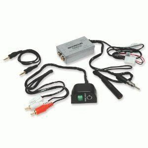
FM modulator
Music center on FM modulator
Today, motorists are offered an interesting feature: listening to flash media through the car’s receiver. A key fob is used where the memory device is connected. Then the FM modulator works like a walkie-talkie. Emits radio waves that the car's receiver can pick up. Both devices are tuned to an arbitrary FM frequency, and nearby listeners (receiver owners) enjoy the content from the flash drive.
The invention is based on the fact that the transmission power is low. However, it is sufficient for the components of the music center to work in harmony. An FM modulator is used to create autonomous systems. If you assemble a music center and include a receiver (any old Soviet one), you can listen to flash drives on decent speakers, even in a car. The gadget is powered by a cigarette lighter; the battery is suitable as a source, just like a computer power supply.
It is possible to make a music center yourself, as indicated, if you have already purchased an FM modulator. There is no need to add an amplifier; the receiver has a built-in one. But for working with large speakers, an extra cascade will not hurt.
Don't forget that speakers are loaded with electronics for good reason: radio equipment does not like vibrations, especially powerful low frequencies. For this reason, collect electronic components not in one box best idea. It’s ideal to plug a couple of speakers from an old tape recorder into the box. We believe that loudspeakers are designed to coexist with electronics without causing mutual harm.
Note! For smart people who underestimate the role of vibrations, we recommend reading about the reasons for the crash of the space shuttle Columbia in 2003.
An FM modulator can be purchased for about 300 rubles. If you have an old receiver and can assemble a low-frequency amplifier, be sure to try it. Anyone will do Tourist. If a station appears on the working channel of the FM modulator, you just need to rebuild it and the receiver. This is not very convenient when constantly changing broadcast zones.
Many car enthusiasts have probably thought about using a car radio at home, in the country or in the garage in order to be able to listen to music not only in the car. Several questions arise: is it possible to do this and how to connect the car radio at home yourself?
A good radio usually costs much less than any music center, and with multi-channel outputs, it becomes possible to assemble a full-fledged home theater. Which will have decent sound quality for a modest amount, but you will still need to devote a little of your time to this moment.
Why do we use a computer power supply?
Connecting a radio from a computer power supply is the most common example of connecting a radio at home. You can also use a battery instead of a power supply, but this method is not very convenient, since it needs constant recharging.
Using a power supply is another one of the most budget-friendly methods; you can purchase a used power supply, or use an old computer as a donor. Before connecting it, you must check its functionality, make sure that it is working properly, and if problems are found, the unit must be repaired or replaced. To do this, we need to perform the following algorithm of actions.
Inspection and troubleshooting of the power supply.

If you purchased a new power supply, then you can safely skip this point.
- Turn on the computer power supply to check the output voltage. Make sure that when current is applied, the cooler (fan) installed on the rear starts spinning.
ATTENTION. Before starting the following steps, make sure that you have disconnected the computer unit from the power supply.
- Open the lid and look inside the unit, there will probably be a lot of dust there, wipe everything thoroughly with a dry cloth, you can also use a vacuum cleaner.
- After cleaning off dirt and dust, carefully inspect the board contacts for defects and cracks in the solder.
- Carefully inspect the capacitors located on the board, if they are swollen, this indicates that the block is faulty, or it does not have long to live. (capacitors are circled in red in the picture above) Swollen capacitors must be replaced. This process requires caution, as high voltage capacitors contain a residual charge of current, from which you can get a light but very noticeable electric shock.
- Assemble the power supply and start connecting
How is the radio connected to the power supply?

To connect at home you will need necessary materials and equipment:
- the computer's power source, this is our unit; its power should be 300-350 watts;
- car radio;
- acoustic speakers or speakers;
- wires with a cross-section of more than 1.5 mm.
The acoustics must be of high quality, the device has a four-channel output, and a speaker can be connected to each output. For louder sound, you should choose speakers with a resistance of 4 ohms, usually car speakers. Home acoustics have an impedance of 8 ohms.
Connecting a car radio to a computer power supply involves several main steps:

If after reading it seems that there is not enough information, read the article “”
Video instructions on how to connect a radio via a power supply
We really hope that in this article you have found the answers to your question, please rate the article on a 5-point scale, if you have comments, suggestions or you know something that is not indicated in this article, please let us know! Leave your comment below. This will help make the information on the site even more useful.
 (1 ratings, on average: 5,00 out of 5)