How to correctly calculate the cross-section of a ventilation duct. Calculation of the cross-section of air ducts Calculation of air ducts program
Many inexperienced owners of houses or apartments underestimate the importance of ventilation, and thus make an extremely serious mistake. Insufficient or improper organization of air exchange means stagnation with a sharp deterioration of the microclimate in the premises, increased humidity, the development of pathogenic microflora, which ultimately leads, at best, to rapid deterioration of the finishing and property in the apartment, and in the future - to persistent health disorders, often developing into dangerous forms.
No matter how the ventilation of a house or apartment is organized, it must comply with certain standards. And one of the key indicators is the volume of fresh air entering the premises within an hour. All other calculations of natural, supply, exhaust or combined ventilation in one way or another will be based precisely on the standards of air supply to residential premises. It’s easy to find the corresponding tables with standards on the Internet, but it’s even easier to use a special calculator for calculating supply ventilation standards.
The reader will find some explanations on the calculations below.
Let's start, perhaps, with natural and. As the name implies, the first type includes ventilation and everything that has nothing to do with devices. Accordingly, mechanical ventilation includes fans, hoods, supply valves and other equipment for creating forced air flow.
It is good for the moderate speed of this flow, which creates comfortable indoor conditions for a person - the wind is not felt. Although properly installed high-quality forced ventilation also does not bring drafts. But there is also a minus: at low air flow rates with natural ventilation, a wider cross-section is required for its supply. As a rule, the most effective ventilation is provided with fully open windows or doors, which speeds up the air exchange process, but can negatively affect the health of residents, especially in the winter. If we ventilate the house by partially opening the windows or completely opening the vents, such ventilation requires about 30–75 minutes, and here the window frame may freeze, which may well lead to condensation, and cold air entering for a long time leads to health problems . Open windows speed up air exchange in the room; through ventilation will take approximately 4–10 minutes, which is safe for window frames, but with such ventilation almost all the heat in the house goes outside, and for a long time the temperature inside the premises is quite low, which again increases the risk diseases.
You should also not forget about the increasingly popular supply valves, which are installed not only on windows, but also on walls inside rooms (wall supply valve), if the design of the windows does not provide for such valves. The wall valve provides air infiltration and is an oblong pipe installed through the wall, closed on both sides with grilles and adjustable from the inside. It can be either completely open or completely closed. For convenience in the interior, it is recommended to place such a valve next to the window, since it can be hidden under tulle, and the flow of passing air will be heated by radiators located under the window sills.
For normal air circulation throughout the apartment, it is necessary to ensure its free movement. To do this, transfer grilles are placed on the interior doors so that the air moves smoothly from the supply systems to the exhaust systems, passing throughout the house, through all the rooms. It is important to consider that the correct flow is considered to be the one in which the smelliest room (toilet, bathroom, kitchen) is the last. If it is not possible to install a flow grille, it is enough to simply leave a gap between the door and the floor, about 2 cm. This is enough for air to move easily around the house.
In cases where natural ventilation is not enough or there is no desire to provide it, they switch to using mechanical ventilation.
When installing a ventilation system, it is important to correctly select and determine the parameters of all elements of the system. It is necessary to find the required amount of air, select equipment, calculate air ducts, fittings and other components of the ventilation network. How are ventilation ducts calculated? What affects their size and cross-section? Let's look at this question in more detail.
Air ducts must be calculated from two points of view. Firstly, the required section and shape are selected. In this case, it is necessary to take into account the amount of air and other network parameters. Also, already during manufacturing, the amount of material, for example, tin, for the manufacture of pipes and shaped elements is calculated. This calculation of the area of the air ducts allows you to determine in advance the quantity and cost of the material.
Duct types
To begin with, let’s say a few words about materials and types of air ducts. This is important because, depending on the shape of the air ducts, there are features of its calculation and choice of cross-sectional area. It is also important to focus on the material, since the characteristics of air movement and the interaction of the flow with the walls depend on it.
In short, the air ducts are:
- Metal made of galvanized or black steel, stainless steel.
- Flexible made of aluminum or plastic film.
- Hard plastic.
- Fabric.
The shape of air ducts is made of round, rectangular and oval. The most commonly used are round and rectangular pipes.
Most of the air ducts described are manufactured in a factory, for example, flexible plastic or fabric, and it is difficult to manufacture them on site or in a small workshop. Most of the products that require calculation are made from galvanized steel or stainless steel.
Both rectangular and round air ducts are made from galvanized steel, and production does not require particularly expensive equipment. In most cases, a bending machine and a device for making round pipes are sufficient. Not counting small hand tools.
Calculation of the cross section of the duct
The main task that arises when calculating air ducts is the choice of cross-section and shape of the product. This process takes place when designing a system both in specialized companies and in self-manufacturing. It is necessary to calculate the diameter of the air duct or the sides of the rectangle, and select the optimal value of the cross-sectional area.
The cross section is calculated in two ways:
- permissible speeds;
- constant pressure loss.
The permissible speed method is simpler for non-specialists, so let’s look at it in general terms.
Calculation of the cross-section of air ducts using the method of permissible velocities
Calculation of the cross-section of the ventilation duct using the permissible speed method is based on the normalized maximum speed. The speed is selected for each type of room and duct section depending on the recommended values. For each type of building, there are maximum permissible speeds in the main air ducts and branches, above which the use of the system is difficult due to noise and strong pressure losses.
Rice. 1 (Network diagram for calculation)

In any case, before starting the calculation it is necessary to draw up a system plan. First you need to calculate the required amount of air that needs to be supplied and removed from the room. Further work will be based on this calculation.
The process of calculating a cross section using the permissible velocity method simply consists of the following steps:
- An air duct diagram is created, which marks the sections and the estimated amount of air that will be transported through them. It is better to indicate on it all the grilles, diffusers, cross-section changes, turns and valves.
- Based on the selected maximum speed and amount of air, the cross-section of the air duct, its diameter or the size of the sides of the rectangle are calculated.
- Once all the system parameters are known, you can select a fan of the required performance and pressure. The selection of a fan is based on calculating the pressure drop in the network. This is much more difficult than simply selecting the cross-section of the air duct for each section. We will consider this issue in general terms. Because sometimes they simply select a fan with a small margin.
To calculate, you need to know the parameters of the maximum air speed. They are taken from reference books and normative literature. The table shows values for some buildings and areas of the system.
Standard speed
The values are approximate, but allow you to create a system with minimal noise.
Fig. 2 (Nomogram of a round tin air duct)
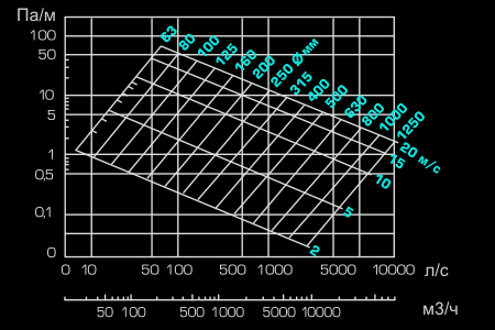
How to use these values? They must be substituted into the formula or nomograms (diagrams) used for different shapes and types of air ducts.
Nomograms are usually given in regulatory literature or in the instructions and descriptions of air ducts from a specific manufacturer. For example, all flexible air ducts are equipped with such circuits. For tin pipes, data can be found in the documents and on the manufacturer’s website.
In principle, you can not use a nomogram, but find the required cross-sectional area based on air speed. And select the area according to the diameter or width and length of the rectangular section.
Example
Let's look at an example. The figure shows a nomogram for a round air duct made of tin. The nomogram is also useful in that it can be used to clarify the pressure loss in a section of the air duct at a given speed. This data will be needed later to select a fan.
So, which air duct to choose on the network section (branch) from the grille to the main line, through which 100 m³/h will be pumped? On the nomogram we find the intersection of a given amount of air with the maximum speed line for a branch of 4 m/s. We also find the nearest (larger) diameter not far from this point. This is a pipe with a diameter of 100 mm.
In the same way we find the section for each section. Everything has been selected. Now all that remains is to select the fan and calculate the air ducts and fittings (if necessary for production).
Fan selection
An integral part of the permissible speed method is the calculation of pressure losses in the air duct network to select a fan of the required performance and pressure.
Pressure loss on straight sections
In principle, the required fan performance can be found by adding up the required amount of air for all rooms of the building and selecting a suitable model from the manufacturer’s catalog. But the problem is that the maximum amount of air specified in the documentation for the fan can only be supplied without a network of air ducts. And when a pipe is connected, its performance will drop depending on the pressure loss in the network.
To do this, the documentation gives each fan a performance diagram depending on the pressure drop in the network. How to calculate this fall? To do this you need to define:
- pressure drop on level sections of air ducts;
- losses on gratings, turns, tees and other shaped elements and obstacles in the network (local resistances).
Pressure losses in sections of air ducts are calculated using the same nomogram. From the point of intersection of the line of air speed in the selected air duct and its diameter, we find the pressure loss in pascals per meter. Next, we calculate the total pressure loss over a section of a certain diameter by multiplying the specific loss by the length.
For our example with a 100 mm air duct and a speed of about 4 m/s, the pressure loss will be about 2 Pa/m.
Pressure loss at local resistances
Calculating pressure losses on turns, bends, tees, changes in cross-section and transitions is much more difficult than on straight sections. For this, the same diagram above indicates all the elements that may impede movement.
Fig 3 (Some k.m.s.)

Next, it is necessary for each such local resistance in the regulatory literature to find the coefficient of local resistance (k.m.s), which is denoted by the letter ζ (zetta). The pressure loss on each such element is determined by the formula:
Pm. s.=ζ×Pd
where Pd=V2×ρ/2 - dynamic pressure (V - speed, ρ - air density).
For example, if in the area we are already considering with a diameter of 100 mm with an air speed of 4 m/s there will be a round outlet (turn 90 degrees) to the m.s. which is 0.21 (according to the table), the pressure loss on it will be
- Pm. s. = 0.21 · 42 · (1.2/2) = 2.0 Pa.
The average air density at a temperature of 20 degrees is 1.2 kg/m3.
Fig 4 (Example table)
A fan is selected based on the parameters found.
Calculation of material for air ducts and fittings
Calculation of the area of air ducts and shaped products is necessary during their production. It is done in order to determine the amount of material (tin) for the manufacture of a section of pipe or any shaped element.
For calculations, you only need to use formulas from geometry. For example, for a round air duct we find the diameter of the circle, multiplying it by the length of the section to obtain the area of the outer surface of the pipe.
To make 1 meter of pipeline with a diameter of 100 mm you will need: π·D·1=3.14·0.1·1=0.314 m² of sheet metal. It is also necessary to take into account 10-15 mm of margin for the connection. A rectangular air duct is also calculated.
The calculation of shaped parts of air ducts is complicated by the fact that there are no specific formulas for it, as for a round or rectangular section. For each element it is necessary to cut and calculate the required amount of materials. This is done in production or in tinsmith shops.
Comments:
- Why do you need to know about the area of air ducts?
- How to calculate the area of material used?
- Calculation of duct area
The possible concentration in enclosed spaces of air contaminated with dust, water vapor and gases, products of thermal processing of food, forces the installation of ventilation systems. For these systems to be effective, serious calculations have to be made, including calculation of the area of the air ducts.
Having found out a number of characteristics of the facility under construction, including the areas and volumes of individual premises, the features of their operation and the number of people who will be there, specialists, using a special formula, can establish the design ventilation performance. After this, it becomes possible to calculate the cross-sectional area of the air duct, which will ensure the optimal level of ventilation of the interior.
Why do you need to know about the area of air ducts?
Ventilation of premises is a rather complex system. One of the most important parts of the air distribution network is the air duct complex. Not only the correct location in the room or cost savings, but most importantly, the optimal ventilation parameters that guarantee a person comfortable living conditions depend on the high-quality calculation of its configuration and working area (both the pipe and the total material required for the manufacture of the air duct).
Figure 1. Formula for determining the diameter of the working line.
In particular, it is necessary to calculate the area in such a way that the result is a structure capable of passing the required volume of air while meeting other requirements for modern ventilation systems. It should be understood that correct calculation of the area leads to the elimination of air pressure losses, compliance with sanitary standards for the speed and noise level of air flowing through the air ducts.
At the same time, an accurate idea of the area occupied by pipes makes it possible to designate the most suitable place in the room for the ventilation system.
Return to contents
How to calculate the area of material used?
Calculation of the optimal air duct area is directly dependent on factors such as the volume of air supplied to one or more rooms, its speed and air pressure loss.
At the same time, the calculation of the amount of material required for its manufacture depends both on the cross-sectional area (dimensions of the ventilation channel), and on the number of rooms into which it is necessary to pump fresh air, and on the design features of the ventilation system.
When calculating the cross-sectional area, it should be borne in mind that the larger it is, the lower the speed of air passage through the air duct pipes.

At the same time, there will be less aerodynamic noise in such a highway, and the operation of forced ventilation systems will require less electricity. To calculate the area of air ducts, you need to apply a special formula.
To calculate the total area of material that needs to be taken to assemble air ducts, you need to know the configuration and basic dimensions of the system being designed. In particular, to calculate for round air distribution pipes, quantities such as the diameter and total length of the entire line will be required. At the same time, the volume of material used for rectangular structures is calculated based on the width, height and total length of the air duct.
When making general calculations of material requirements for the entire highway, it is also necessary to take into account bends and half-bends of various configurations. Thus, correct calculations of a round element are impossible without knowing its diameter and angle of rotation. When calculating the area of material for a rectangular outlet, components such as width, height and angle of rotation of the outlet are involved.
It is worth noting that each such calculation uses its own formula. Most often, pipes and fittings are made of galvanized steel in accordance with the technical requirements of SNiP 41-01-2003 (Appendix N).
Return to contents
Calculation of duct area

The size of the ventilation pipe is influenced by such characteristics as the mass of air pumped into the premises, the speed of the flow and the level of its pressure on the walls and other elements of the pipeline.
It is enough, without calculating all the consequences, to reduce the diameter of the line, but the air flow speed will immediately increase, which will lead to an increase in pressure along the entire length of the system and in places of resistance. In addition to the appearance of excessive noise and unpleasant vibration of the pipe, electric ones will also record an increase in energy consumption.
However, it is not always possible and necessary to increase the cross-section of the ventilation line in pursuit of eliminating these shortcomings. First of all, this can be prevented by the limited dimensions of the premises. Therefore, you should be especially careful when calculating the pipe area.
To determine this parameter, you must apply the following special formula:
Sc = L x 2.778/V, where
Sc is the calculated channel area (cm 2);
L - air flow moving through the pipe (m 3 / hour);
V is the speed of air movement along the ventilation line (m/sec);
2.778 - coefficient of coordination of dimensions (for example, meters and centimeters).

The result of the calculations - the estimated pipe area - is expressed in square centimeters, since in these units of measurement it is considered by specialists as the most convenient for analysis.
In addition to the calculated cross-sectional area of the pipeline, it is important to establish the actual cross-sectional area of the pipe. It should be borne in mind that for each of the main cross-section profiles - round and rectangular - its own separate calculation scheme has been adopted. So, to fix the actual area of a circular pipeline, the following special formula is used.
In order for the air exchange in the house to be “correct,” an aerodynamic calculation of the air ducts is needed even at the stage of drawing up a ventilation project.
Air masses moving through the channels of the ventilation system are taken as an incompressible fluid during calculations. And this is completely acceptable, because too much pressure does not form in the air ducts. In fact, pressure is formed as a result of air friction against the walls of the channels, as well as when resistance of a local nature appears (these include pressure surges at places where direction changes, when connecting/disconnecting air flows, in areas where control devices or same where the diameter of the ventilation duct changes).
Note! The concept of aerodynamic calculation includes determining the cross-section of each section of the ventilation network that ensures the movement of air flows. Moreover, the pressure generated as a result of these movements is also determined.

In accordance with many years of experience, we can safely say that sometimes some of these indicators are already known at the time of calculation. Below are situations that are often encountered in such cases.
- The cross-sectional area of the cross-section of the ventilation system is already known; it is necessary to determine the pressure that may be required in order for the required amount of gas to move. This often happens in those air conditioning lines where the cross-sectional dimensions were based on technical or architectural characteristics.
- We already know the pressure, but we need to determine the cross-section of the network to provide the ventilated room with the required volume of oxygen. This situation is inherent in natural ventilation networks, in which the existing pressure cannot be changed.
- We do not know about any of the indicators, therefore, we need to determine both the pressure in the main and the cross-section. This situation occurs in most cases in the construction of houses.

Features of aerodynamic calculations
Let's get acquainted with the general methodology for carrying out this kind of calculations, provided that both the cross section and the pressure are unknown to us. Let us immediately make a reservation that the aerodynamic calculation should be carried out only after the required volumes of air masses have been determined (they will pass through the air conditioning system) and the approximate location of each of the air ducts in the network has been designed.

And in order to carry out the calculation, it is necessary to draw an axonometric diagram, which will contain a list of all network elements, as well as their exact dimensions. In accordance with the ventilation system plan, the total length of the air ducts is calculated. After this, the entire system should be divided into segments with homogeneous characteristics, according to which (only separately!) the air flow will be determined. What is typical is that for each of the homogeneous sections of the system, a separate aerodynamic calculation of the air ducts should be carried out, because each of them has its own speed of movement of air flows, as well as a permanent flow rate. All the obtained indicators must be entered into the axonometric diagram already mentioned above, and then, as you probably already guessed, you need to select the main highway.
How to determine the speed in ventilation ducts?
As can be judged from everything said above, as the main highway it is necessary to choose the chain of successive sections of the network that is the longest; in this case, the numbering should begin exclusively from the most remote section. As for the parameters of each section (and these include air flow, section length, its serial number, etc.), they should also be entered into the calculation table. Then, when the application is completed, the shape of the cross-section is selected and its cross-sections and dimensions are determined.

LP/VT = FP.
What do these abbreviations stand for? Let's try to figure it out. So, in our formula:
- LP is the specific air flow rate in the selected area;
- VT is the speed at which air masses move through this area (measured in meters per second);
- FP is the cross-sectional area of the channel we need.
Typically, when determining the speed of movement, it is necessary to be guided, first of all, by considerations of economy and noise level of the entire ventilation network.
Note! Based on the indicator obtained in this way (we are talking about the cross section), it is necessary to select an air duct with standard values, and its actual cross section (denoted by the abbreviation FF) should be as close as possible to the previously calculated one.
LP/ FF = VФ.
Having received the required speed indicator, it is necessary to calculate how much the pressure in the system will decrease due to friction against the walls of the channels (for this you need to use a special table). As for the local resistance for each section, they should be calculated separately and then summed up into a common indicator. Then, by summing up the local resistance and losses due to friction, the total losses in the air conditioning system can be obtained. In the future, this value will be used to calculate the required amount of gas masses in the ventilation channels.

Air heating unit
Previously, we talked about what an air heating unit is, talked about its advantages and areas of application, in addition to this article, we advise you to read this information
How to calculate the pressure in the ventilation network
In order to determine the expected pressure for each individual area, you must use the formula below:
Н x g (РН – РВ) = DPE.
Now let's try to figure out what each of these abbreviations means. So:
- H in this case denotes the difference in the elevations of the mine mouth and the intake grid;
- RV and RN are an indicator of gas density, both outside and inside the ventilation network, respectively (measured in kilograms per cubic meter);
- Finally, DPE is an indicator of what the natural available pressure should be.
We continue to analyze the aerodynamic calculation of air ducts. To determine the internal and external density, it is necessary to use a reference table, and the temperature indicator inside/outside must also be taken into account. As a rule, the standard outside temperature is taken as plus 5 degrees, regardless of which specific region of the country construction work is planned. And if the temperature outside is lower, then as a result the injection into the ventilation system will increase, which, in turn, will cause the volumes of incoming air masses to be exceeded. And if the outside temperature, on the contrary, is higher, then the pressure in the line will decrease because of this, although this trouble, by the way, can be compensated for by opening the vents/windows.

As for the main task of any described calculation, it is to select such air ducts where losses on sections (we are talking about the value? (R*l*?+Z)) will be lower than the current DPE indicator or, as an option, at least equal to him. For greater clarity, we present the point described above in the form of a small formula:
DPE? ?(R*l*?+Z).
Now let’s take a closer look at what the abbreviations used in this formula mean. Let's start from the end:
- Z in this case is an indicator indicating a decrease in air speed due to local resistance;
- ? – this is the value, more precisely, the coefficient of the roughness of the walls in the pipeline;
- l is another simple value that indicates the length of the selected section (measured in meters);
- Finally, R is the friction loss index (measured in pascals per meter).


![]()
Well, we’ve sorted that out, now let’s find out a little more about the roughness index (that is?). This indicator depends only on what materials were used in the manufacture of the channels. It is worth noting that the speed of air movement can also be different, so this indicator should also be taken into account.
Speed – 0.4 meters per second
In this case, the roughness indicator will be as follows:
- for plaster using reinforcing mesh – 1.48;
- for slag gypsum - about 1.08;
- for ordinary brick - 1.25;
- and for slag concrete, respectively, 1.11.
Speed – 0.8 meters per second
Here the described indicators will look like this:
- for plaster using reinforcing mesh – 1.69;
- for slag gypsum – 1.13;
- for ordinary brick – 1.40;
- finally, for slag concrete – 1.19.
Let's slightly increase the speed of the air masses.
Speed – 1.20 meters per second
For this value, the roughness indicators will be as follows:
- for plaster using reinforcing mesh – 1.84;
- for slag gypsum – 1.18;
- for ordinary brick - 1.50;
- and, therefore, for slag concrete it is about 1.31.
And the last indicator of speed.
Speed – 1.60 meters per second
Here the situation will look like this:
- for plaster using reinforcing mesh, the roughness will be 1.95;
- for slag gypsum – 1.22;
- for ordinary brick – 1.58;
- and, finally, for slag concrete - 1.31.
Note! We've sorted out the roughness, but it's worth noting one more important point: it is advisable to take into account a small margin, fluctuating between ten and fifteen percent.
Understanding the general ventilation calculations
When performing an aerodynamic calculation of air ducts, you must take into account all the characteristics of the ventilation shaft (these characteristics are given below in the form of a list).
- Dynamic pressure (to determine it, the formula is used - DPE?/2 = P).
- Air mass flow (it is designated by the letter L and measured in cubic meters per hour).
- Pressure loss due to air friction against the internal walls (denoted by the letter R, measured in pascals per meter).
- Diameter of air ducts (to calculate this indicator, the following formula is used: 2*a*b/(a+b); in this formula, the values a, b are the cross-sectional dimensions of the ducts and are measured in millimeters).
- Finally, speed is V, measured in meters per second, which we mentioned earlier.
 >
>
As for the actual sequence of actions during the calculation, it should look something like this.
Step one. First, you should determine the required channel area, for which the formula below is used:
I/(3600xVpek) = F.
Let's understand the values:
- F in this case is, of course, the area, which is measured in square meters;
- Vpek is the desired speed of air movement, which is measured in meters per second (for channels, a speed of 0.5-1.0 meters per second is assumed, for mines - about 1.5 meters).
Step three. The next step is to determine the appropriate diameter of the duct (indicated by the letter d).
Step four. Then the remaining indicators are determined: pressure (denoted as P), speed of movement (abbreviated V) and, therefore, reduction (abbreviated R). To do this, it is necessary to use nomograms according to d and L, as well as the corresponding tables of coefficients.
Step five. Using other tables of coefficients (we are talking about local resistance indicators), it is necessary to determine how much the impact of air will decrease due to local resistance Z.
Step six. At the last stage of calculations, it is necessary to determine the total losses on each individual section of the ventilation line.
Pay attention to one important point! So, if the total losses are lower than the existing pressure, then such a ventilation system can be considered effective. But if the losses exceed the pressure, then it may be necessary to install a special throttle diaphragm in the ventilation system. Thanks to this diaphragm, excess pressure will be dampened.
We also note that if the ventilation system is designed to serve several rooms at once, for which the air pressure must be different, then during the calculations it is also necessary to take into account the indicator of vacuum or pressure, which must be added to the overall loss indicator.
Video - How to make calculations using the VIX-STUDIO program
Aerodynamic calculation of air ducts is considered a mandatory procedure, an important component of planning ventilation systems. Thanks to this calculation, you can find out how effectively the premises are ventilated for a particular channel cross-section. And the effective functioning of ventilation, in turn, ensures maximum comfort of your stay in the house.
Example of calculations. The conditions in this case are as follows: the building is of an administrative nature, has three floors.

Although there are many programs for this, many parameters are still determined the old fashioned way, using formulas. Calculation of the ventilation load, area, power and parameters of individual elements is carried out after drawing up the diagram and distribution of the equipment.
This is a difficult task that only professionals can do. But if you need to calculate the area of some ventilation elements or the cross-section of air ducts for a small cottage, you can really do it yourself.
Air exchange calculation

If there are no toxic emissions in the room or their volume is within acceptable limits, air exchange or ventilation load is calculated using the formula:
R= n * R1,
Here R1- air requirement of one employee, in cubic meters per hour, n- number of permanent employees in the premises.
If the volume of the room per employee is more than 40 cubic meters and natural ventilation is working, there is no need to calculate air exchange.
For domestic, sanitary and utility premises, ventilation calculations based on hazards are made based on approved air exchange rate standards:
- for administrative buildings (exhaust) - 1.5;
- halls (serving) - 2;
- conference rooms for up to 100 people with a capacity (for supply and exhaust) - 3;
- rest rooms: supply 5, exhaust 4.
For industrial premises in which hazardous substances are constantly or periodically released into the air, ventilation calculations are made based on hazardous substances.
Air exchange by pollutants (vapors and gases) is determined by the formula:
Q= K\(k2- k1),
Here TO- the amount of steam or gas appearing in the building, in mg/h, k2- steam or gas content in the outflow, usually the value is equal to the maximum permissible concentration, k1- gas or steam content in the inlet.
The concentration of harmful substances in the inlet is allowed to be up to 1/3 of the maximum permissible concentration.
For rooms with the release of excess heat, air exchange is calculated using the formula:
Q= Ghut\c(tyx - tn),
Here Gizb- excess heat drawn out is measured in W, With- specific heat capacity by mass, c=1 kJ, tyx- temperature of air removed from the room, tn- inlet temperature.
Heat load calculation

Calculation of the thermal load on ventilation is carried out according to the formula:
Qin=Vn*k * p * CR(tvn -tnro),
in the formula for calculating the thermal load on ventilation Vn- external volume of the building in cubic meters, k- air exchange rate, tvn- average temperature in the building, in degrees Celsius, tnro- outside air temperature used in heating calculations, in degrees Celsius, R- air density, in kg/cubic meter, Wed- heat capacity of air, in kJ/cubic meter Celsius.
If the air temperature is lower tnro the air exchange rate is reduced, and the heat consumption rate is considered equal to Qв, a constant value.
If, when calculating the heat load for ventilation, it is impossible to reduce the air exchange rate, the heat consumption is calculated based on the heating temperature.
Heat consumption for ventilation
The specific annual heat consumption for ventilation is calculated as follows:
Q= * b * (1-E),
in the formula for calculating heat consumption for ventilation Qo- total heat loss of the building during the heating season, Qb- domestic heat inputs, Qs- heat input from outside (sun), n- coefficient of thermal inertia of walls and ceilings, E- reduction factor. For individual heating systems 0,15 , for central 0,1 , b- heat loss coefficient:
- 1,11 - for tower buildings;
- 1,13 - for multi-section and multi-entry buildings;
- 1,07 - for buildings with warm attics and basements.
Calculation of the diameter of air ducts

Diameters and sections are calculated after the general diagram of the system has been drawn up. When calculating the diameters of ventilation air ducts, the following indicators are taken into account:
- Air volume (supply or exhaust air), which must pass through the pipe in a given period of time, cubic meters per hour;
- Air speed. If, when calculating ventilation pipes, the flow rate is underestimated, air ducts with a cross-section that are too large will be installed, which entails additional costs. Excessive speed leads to vibrations, increased aerodynamic noise and increased equipment power. The speed of movement on the inflow is 1.5 - 8 m/sec, it varies depending on the area;
- Ventilation pipe material. When calculating the diameter, this indicator affects the wall resistance. For example, black steel with rough walls has the highest resistance. Therefore, the calculated diameter of the ventilation duct will have to be slightly increased compared to the standards for plastic or stainless steel.
Table 1. Optimal air flow speed in ventilation pipes.
When the throughput of future air ducts is known, the cross-section of the ventilation duct can be calculated:
S= R\3600 v,
Here v- speed of air flow, in m/s, R- air consumption, cubic meters/h.
The number 3600 is a time coefficient.
![]()
Here: D- diameter of the ventilation pipe, m.
Calculation of the area of ventilation elements
Calculation of the ventilation area is necessary when the elements are made of sheet metal and it is necessary to determine the quantity and cost of the material.
The ventilation area is calculated using electronic calculators or special programs; many of them can be found on the Internet.
We will provide several tabular values of the most popular ventilation elements.
| Diameter, mm | Length, m | |||
| 1 | 1,5 | 2 | 2,5 | |
| 100 | 0,3 | 0,5 | 0,6 | 0,8 |
| 125 | 0,4 | 0,6 | 0,8 | 1 |
| 160 | 0,5 | 0,8 | 1 | 1,3 |
| 200 | 0,6 | 0,9 | 1,3 | 1,6 |
| 250 | 0,8 | 1,2 | 1,6 | 2 |
| 280 | 0,9 | 1,3 | 1,8 | 2,2 |
| 315 | 1 | 1,5 | 2 | 2,5 |
table 2. Area of straight round air ducts.
Area value in sq. m. at the intersection of horizontal and vertical stitching.
| Diameter, mm | Angle, degrees | ||||
| 15 | 30 | 45 | 60 | 90 | |
| 100 | 0,04 | 0,05 | 0,06 | 0,06 | 0,08 |
| 125 | 0,05 | 0,06 | 0,08 | 0,09 | 0,12 |
| 160 | 0,07 | 0,09 | 0,11 | 0,13 | 0,18 |
| 200 | 0,1 | 0,13 | 0,16 | 0,19 | 0,26 |
| 250 | 0,13 | 0,18 | 0,23 | 0,28 | 0,39 |
| 280 | 0,15 | 0,22 | 0,28 | 0,35 | 0,47 |
| 315 | 0,18 | 0,26 | 0,34 | 0,42 | 0,59 |
Table 3. Calculation of the area of bends and half-bends of circular cross-section.
Calculation of diffusers and grilles

Diffusers are used to supply or remove air from a room. The cleanliness and temperature of the air in every corner of the room depends on the correct calculation of the number and location of ventilation diffusers. If you install more diffusers, the pressure in the system will increase and the speed will drop.
The number of ventilation diffusers is calculated as follows:
N= R\(2820 * v *D*D),
Here R- throughput, in cubic meters per hour, v- air speed, m/s, D- diameter of one diffuser in meters.
The number of ventilation grilles can be calculated using the formula:
N= R\(3600 * v * S),
Here R- air flow in cubic meters per hour, v- air speed in the system, m/s, S- cross-sectional area of one grating, sq.m.
Calculation of a duct heater

The calculation of an electric ventilation heater is carried out as follows:
P= v * 0,36 * ∆ T
Here v- volume of air passed through the heater in cubic meters per hour, ∆T- the difference between the air temperature outside and inside, which must be provided by the heater.
This indicator varies between 10 - 20, the exact figure is set by the client.
Calculation of a heater for ventilation begins with calculating the frontal cross-sectional area:
Af=R * p\3600 * Vp,
Here R- volume of inlet flow, cubic meters per hour, p- density of atmospheric air, kg\cub.m, Vp- mass air speed in the area.
The cross-sectional size is necessary to determine the dimensions of the ventilation heater. If, according to calculations, the cross-sectional area turns out to be too large, it is necessary to consider the option of a cascade of heat exchangers with a total calculated area.
The mass velocity indicator is determined through the frontal area of the heat exchangers:
Vp= R * p\3600 * Af.fact
To further calculate the ventilation heater, we determine the amount of heat required to warm the air flow:
Q=0,278 * W * c (TP-Ty),
Here W- warm air consumption, kg/hour, Tp- supply air temperature, degrees Celsius, That- outside air temperature, degrees Celsius, c- specific heat capacity of air, constant value 1.005.
To create a favorable microclimate in industrial and residential premises, it is necessary to install a high-quality ventilation system. Particular attention must be paid to the length and diameter of the pipe for natural ventilation, since the efficiency, productivity and reliability of air ducts depend on correct calculations.
What are the requirements for ventilation pipes?
The main purpose of the duct for natural ventilation is to remove exhaust air from the room.

When installing systems in homes, offices and other facilities, the following points must be taken into account:
- the diameter of the pipe for natural ventilation must be at least 15 cm;
- when installing in residential premises and food industry facilities, anti-corrosion characteristics are important, otherwise metal surfaces will rust under the influence of high humidity;
- the lighter the structure, the easier the installation and maintenance;
- performance also depends on the thickness of the air duct; the thinner, the greater the throughput;
- fire safety level – no harmful substances should be released during combustion.
If you do not comply with standards (norms) when designing, installing and choosing the material and diameter of PVC ventilation pipes or galvanized steel, then the indoor air will be “heavy” due to high humidity and lack of oxygen. In apartments and houses with poor ventilation, windows often fog up, the walls in the kitchen smoke, and fungus forms.
What material should I choose the air duct from?
There are several types of pipes on the market, differing in the material of manufacture:
Advantages of plastic pipes:
- low cost when compared with air ducts made of other materials;
- anti-corrosion surfaces do not require additional protection or treatment;
- easy to maintain, you can use any detergent for cleaning;
- large selection of pipe diameters for PVC ventilation pipes;
- simple installation, and, if necessary, the structure can be easily dismantled;
- dirt does not accumulate on the surface due to its smoothness;
- When heated, there is no release of harmful and toxic substances to human health.

Metal air ducts are made of galvanized or stainless steel. When considering the characteristics, the following advantages can be identified:
- galvanized and stainless steel pipes are allowed to be used in facilities with high humidity and frequent temperature changes;
- moisture resistance – structures are not subject to corrosion and rust;
- high heat resistance;
- relatively light weight;
- Easy installation - basic knowledge required.

Aluminum foil is used as a material for the manufacture of corrugated air ducts. Main advantages:
- during installation, a minimum number of connections is formed;
- ease of dismantling;
- if necessary, the pipeline is placed at any angle.
Advantages of fabric structures:
- mobility - easy to install and dismantle;
- there are no problems during transportation;
- no condensation under any operating conditions;
- low weight facilitates the fastening process;
- no need for additional insulation.
What are the different types of air ducts?
Depending on the scope and direction of use, not only the diameters of the PVC pipes are selected, but also the shape:

- Spiral shapes are distinguished by increased rigidity and attractive appearance. During installation, connections are made using cardboard or rubber seals and flanges. Systems do not need isolation.
Advice! If you have no experience in this area, then to save your own money and time, it is better to immediately turn to specialists, since calculating the diameter of the pipe for ventilation taking into account the air flow, and carrying out the installation yourself will be very problematic.
- For residential properties (country and country houses), flat shapes would be an ideal option due to the following advantages:
- if necessary, round and flat pipes can be easily combined;
- if the dimensions do not match, then the parameters can be easily adjusted using a construction knife;
- the structures are relatively lightweight;
- Tees and flanges are used as connecting elements.
- Installation of flexible structures occurs without additional elements for connection (flanges, etc.), which greatly simplifies the installation process. The manufacturing material used is laminated polyester film, woven fabric or aluminum foil.
- Round air ducts are more in demand, the demand is explained by the following advantages:
- minimum number of connecting elements;
- easy operation;
- air is well distributed;
- high levels of rigidity;
- simple installation work.
The material of manufacture and the shape of the pipes are determined at the stage of developing design documentation; a large list of points is taken into account here.
How is the diameter of the ventilation pipe determined?
In Russia there are a number of SNiP normative documents that say how to calculate the diameter of a pipe for natural ventilation. The choice is based on the air exchange rate - a determining indicator of how much and how many times per hour the air in the room is replaced.
First you need to do the following:
- calculations are made of the volume of each room in the building - you need to multiply the length, height and width;
- air volume is calculated using the formula: L=n (standardized air exchange rate)*V (room volume);
- the obtained L indicators are rounded up to a multiple of 5;
- the balance is drawn up so that the exhaust and supply air flows coincide in total volume;
- The maximum speed in the central air duct is also taken into account; the indicators should not exceed 5 m/s, and on branch sections of the network no more than 3 m/s.
The diameter of PVC ventilation pipes and other materials is selected according to the data obtained in the table presented:

How to determine the length of the ventilation pipe?
When writing a project, in addition to calculating the diameter of the pipe for natural ventilation, determining the length of the outer part of the air duct is considered an important point. The total value includes the length of all channels in the building through which air circulates and is discharged outside.
Calculations are made according to the table:

The following indicators are taken into account when calculating:
- if a flat duct is used in an installation above the roof, the minimum length should be 0.5 m;
- when installing a ventilation pipe next to the smoke, the height is made the same to prevent smoke from entering the room during the heating season.
The performance, efficiency and uninterrupted operation of the ventilation system largely depends on the correct calculations and compliance with installation requirements. It is better to choose proven companies with a positive reputation!
Industrial ventilation is designed taking into account several facts, all of which are significantly influenced by the cross-section of the air ducts.
- Air exchange rate. During the calculations, the features of the technology, the chemical composition of the harmful compounds released, and the dimensions of the room are taken into account.
- Noisy. Ventilation systems should not worsen working conditions in terms of noise. The cross-section and thickness are selected in such a way as to minimize the noise of air flows.
- Efficiency of the general ventilation system. Several rooms can be connected to one main air duct. Each of them must maintain its own ventilation parameters, and this largely depends on the correct choice of diameters. They are selected in such a way that the size and capabilities of one common fan can provide regulated system modes.
- Economical. The smaller the energy losses in the air ducts, the lower the electrical energy consumption. At the same time, it is necessary to take into account the cost of the equipment and select economically feasible dimensions of the elements.
An effective and economical ventilation system requires complex preliminary calculations; only specialists with higher education can do this. Currently, plastic air ducts are most often used for industrial ventilation; they meet all modern requirements and make it possible to reduce not only the dimensions and cost of the ventilation system, but also the cost of its maintenance.
Air duct diameter calculation
To calculate dimensions, you need to have initial data: the maximum permissible speed of air flow and the volume of air passed per unit of time. This data is taken from the technical characteristics of the ventilation system. The speed of air movement affects the noise of the system, and it is strictly controlled by sanitary government organizations. The volume of air passed must correspond to the parameters of the fans and the required exchange rate. The calculated area of the air duct is determined by the formula Sc = L × 2.778 / V, where:
Sc – cross-sectional area of the air duct in square centimeters; L – maximum air supply (flow rate) in m 3 /hour;
V – design operating air flow speed in meters per second without peak values;
2.778 is the coefficient for converting various metric numbers to diameter values in square centimeters.
Ventilation system designers take into account the following important dependencies:
- If it is necessary to supply the same volume of air, reducing the diameter of the air ducts leads to an increase in air flow speed. This phenomenon has three negative consequences. First, an increase in air speed increases noise, and this parameter is controlled by sanitary standards and cannot exceed permissible values. Secondly, the higher the air speed, the higher the energy losses, the more powerful the fans are needed to ensure the specified operating modes of the system, the larger their sizes. Third, the small dimensions of the air ducts are not able to properly distribute flows between different rooms.

- An unjustified increase in the diameters of air ducts increases the price of the ventilation system and creates difficulties during installation work. Large sizes have a negative impact on the cost of system maintenance and the cost of manufactured products.
The smaller the diameter of the air duct, the faster the air speed. This not only increases noise and vibration, but also increases air flow resistance. Accordingly, to ensure the required calculated exchange rate, it is necessary to install powerful fans, which increases their size and is economically unprofitable at current prices for electrical energy.
With increasing diameters, the above problems disappear, but new ones appear - the complexity of installation and the high cost of large-scale equipment, including various shut-off and control valves. In addition, large-diameter air ducts require a lot of free space for installation; holes have to be made for them in main walls and partitions. Another problem is that if they are used for heating rooms, then the large size of the air duct requires increased costs for thermal protection measures, which further increases the estimated cost of the system.
In simplified versions of the calculations, it is taken into account that the optimal speed of air flows should be in the range of 12–15 m/s, due to this it is possible to slightly reduce their diameter and thickness. Due to the fact that main air ducts in most cases are laid in special technical channels, the noise level can be neglected. In branches that go directly into the premises, the air speed is reduced to 5–6 m/s, thereby reducing noise. The volume of air is taken from the SaniPin tables for each room, depending on its intended dimensions.
Problems arise with long-distance main ducts in large plants or in systems with many branches. For example, with a normalized air flow of 35,000 m 3 /h and an air flow speed of 8 m/s, the diameter of the air duct must be at least 1.5 m with a thickness of more than two millimeters; when the air flow speed increases to 13 m/s, the dimensions of the air ducts are reduced to 1 m.
Pressure loss table

The diameter of the air duct branches is calculated taking into account the requirements for each room. It is possible to use the same dimensions for them, and to change the air parameters, install different adjustable throttle valves. Such options for ventilation systems allow you to automatically change performance indicators taking into account the actual situation. There should be no drafts in the premises caused by ventilation. Creating a favorable microclimate is achieved through the correct choice of installation location for ventilation grilles and their linear dimensions.

The systems themselves are calculated using the constant velocity method and the pressure loss method. Based on these data, the size, type and power of fans are selected, their number is calculated, installation locations are planned, and the dimensions of the air duct are determined.
 (1 ratings, on average: 5,00 out of 5)

