Draw vector diagrams using these diagrams. Construction of vector diagrams
Problem 3
The current vector is constructed first, then the voltage vector. 
Problem 4
Construct a high-quality vector diagram.
We carry out the construction using the properties of the elements. ![]()

Problem 5
Construct a high-quality vector diagram for the circuit, provided that XL>XC.
We carry out the construction using the properties of the elements. 

Task
IN series circuit determine instrument readings, draw up and calculate the power balance, determine the power factor, construct a topographic vector diagram.
R1 = 10 Ohm
R2 = 20 Ohm
C = 31.8 µF
L = 0.127 H
f = 50 Hz ![]()

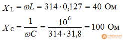
1). Let us determine the total complex resistance of the reactive elements
2). Let's convert the source voltage into algebraic form
3). Let's determine the equivalent circuit resistance
The circuit is active-capacitive in nature
4). Let's determine the current in the circuit
5). The ammeter will show effective value current
![]()
6). Let's determine the voltmeter reading, the effective value of the voltage on the capacitor
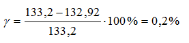
7). Let's determine the power of the source and receivers
Receiver power

From the calculations it is clear that the balance converges with an error of less than a percent
8). Let's determine the power factor

9) construction of a topographic vector diagram
Let's determine the voltages on the circuit elements

Selection of current scale 2 cm - 1 A; voltage 2cm – 50 V
The rule for constructing a vector diagram when elements are included sequentially:
build a current vector
constructing stress vectors
We add the stress vectors according to the parallelogram rule.

Problem 6.1. In the circuit shown in Fig. 6.1, the voltages across the active resistance were measured U R and at the coil terminals U K and also the angle φ between voltage Ū K and current Ī .
The measurements gave the following results: U R = 100 V, U K = 120 V, φ =75º.
It is necessary to determine the value of the input voltage U .
We build a vector diagram of a given circuit (Fig. 6.2).

Since the circuit is unbranched, we begin the construction with the current vector Ī . We draw a vector along it Ū R and add the vector to it Ū K, leading current by angle φ . Vector sum Ū R and Ū K gives the input voltage vector Ū , the length of which, which determines the value of the input voltage, can be found using the cosine theorem:

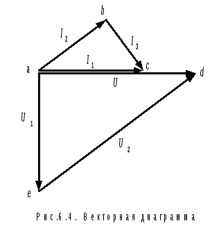
Problem 6.2. In the circuit in Fig. 6.3 resonance.

Find the current value I 3 if U = 80 V, I 2 = 4 A, R = 25 Ohm.
The problem is easily solved using a vector diagram. Since there is resonance in the circuit, the voltage and current at the input of the circuit are in phase, the vectors Ū And Ī 1 are directed in one direction (Fig. 6.4). The voltage in the first section lags behind the current Ī 1 at 90º. Vector Ū 1 is directed perpendicularly downwards. Vector Ū 2 draw from the end of the vector Ū 1 to the end of the vector Ū – so that the equality holds: Ū 1 + Ū 2 = Ū . Current Ī 2 in phase with voltage Ū 2, a Ī 3 is 90º behind it. In total they give a current Ī 1 .
According to Ohm's law for the second branch:
From a triangle ade :
From the similarity of triangles abc And ade follows:

We calculate:

Problem 6.3. To the coil with parameters R And L capacity connected in parallel C (Fig. 6.5, a). It is known that there is resonance in the circuit and the values of two currents are given: I To= 5 A and I = 3 A. What is the capacitance of the capacitor if the supply voltage is U = 220 V, and its frequency f = 50 Hz?
The vector diagram quickly leads to the result (Fig. 6.5, b).

Current Ī to lagging voltage Ū at some angle, current Ī c leads the voltage by 90º. The sum of these two currents gives the total current: Ī = Ī k + Ī With. Since there is resonance in the circuit, the total current vector is directed along the voltage vector.
The current diagram is a right triangle, from which it follows:
Capacitance

and the capacitance of the capacitor
CONCLUSION
The vector diagram gives full information about the electrical circuit. You can even say that it is one of the ways to depict an electrical circuit - its configuration allows you to determine the structure of the circuit. And if it is built to scale, it gives numerical values of voltages and currents on all elements of the circuit, and also allows you to find the values of all resistances.
CONTROL QUESTIONS
1. What is a vector? How are the current and voltage vectors in an electrical circuit designated?
2. What rules do you know for adding vectors?
3. How are the current and voltage vectors directed relative to each other in active resistance, inductance and capacitance?
4. What laws of electrical circuits are used when constructing vector diagrams?
5. From which vector is it advisable to start constructing a vector diagram?
6. In what order should vectors be plotted when constructing a diagram?
CONTROL TASKS


In the diagram given by the teacher, indicate the voltages and currents in all sections and construct a vector diagram.
BIBLIOGRAPHICAL LIST
1. Theoretical foundations of electrical engineering: in 3 volumes. Textbook for universities. Volume 1. – 4th ed. / K.S. Demirchyan, L.R. Neiman, N.V. Korovin, V.L. Chechurin. – St. Petersburg: Peter, 2004, - 463 pp.: ill.
BIBLIOGRAPHICAL LIST
1. Theoretical foundations of electrical engineering: in 3 volumes. Textbook for universities. Volume 1. – 4th ed. / K.S. Demargyan, L.R. Neiman, N.V. Korovin, V.L. Chechurin. – St. Petersburg: Peter, 2004, - 463 pp.: ill.
2. Matyushchenko V.S. Theoretical foundations of electrical engineering. Linear electrical circuits of direct and single-phase sinusoidal currents: textbook. allowance / V.S. Matyushchenko. - Khabarovsk. – Khabarovsk: Publishing house DVGUPS, 2002. – 112 p.
3. Matyushchenko V.S. Calculation of complex electrical circuits of direct and sinusoidal currents: textbook. allowance / V.S. Matyushchenko. – Khabarovsk: Publishing house DVGUPS, 2004. – 69 p.
Basically, vector diagrams are built on the complex plane and
There are two types:- vector diagrams of currents and voltages;
- vector topographic stress diagrams.
All vector diagrams are plotted to scale for both currents and voltages. The coordinate axes are designated on the complex plane +1 And +j. The technique for constructing diagrams depends on the connection diagram of the electrical circuit. If the circuit elements R, L, C are connected in series, then the “reference” in the diagram is the current vector, as common to all elements. Next, voltage vectors are constructed taking into account the phase shift between the current and voltages on the elements (see diagram A). The geometric sum of the voltage vectors must be equal to the voltage vector applied to the electrical circuit.

Diagram A Diagram B
If the circuit elements R, L, C are connected in parallel, then the “reference” in the diagram is the voltage vector, as common to all elements. Next, current vectors are constructed taking into account the phase shift between voltage and currents in the circuit branches (see diagram B). The geometric sum of the current vectors in the branches must be equal to the total current in the electrical circuit.
Topographic stress diagram is a diagram of complex potentials of points in an electrical circuit, laid out in a certain order. The potential of one of the points is assumed to be zero and then two construction options are possible: first, the potentials of the remaining points are calculated relative to this potential; second, from this point the voltage modules on the elements with the corresponding phase shift angles are plotted. The procedure for constructing a topographic diagram is visible in simple example(See Diagram B and Diagram B).


Diagram B Diagram B
IN electrical circuits with a mixed connection of elements, the topographic stress diagram is usually constructed in several stages. In this case, diagrams are first constructed for individual branches of the circuit, which assumes the presence of a vector diagram of currents for the entire circuit, and then combined into a general topographic diagram.
End of work -
 (1 ratings, on average: 5,00 out of 5)

