Which electrical element corresponds to the vector diagram. Serial circuit R, L on alternating current: vector diagram of current and voltages, voltage triangle. Ohm's law in complex form
IN active resistance voltage and current are in phase, so the voltage vectors Ū R and current Ī directed in one direction (Fig. 2.1). They can lie on the same line or on parallel lines. In this case, a bunch of vectors Ū R and Ī may have an arbitrary direction, but in all cases the angle between the vectors is zero .
Note. In order for different vectors lying on the same straight line not to merge and be easily distinguishable from each other, we recommend that they be drawn at some rather small distance from each other.
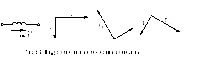
2.2. Inductance
In an inductor, the current lags the voltage in phase by a quarter of a period. In a vector diagram, the angle between vectors Ū L and Ī is 90º. And here is a bunch of vectors Ū L and Ī can be oriented as you like, but their relative position is unchanged. When the diagram is rotated counterclockwise, the voltage vector is in front Ū L , followed by the current vector with a 90º lag Ī (fig.2.2).
2.3. Capacity
In a capacitance, the voltage lags the current by a quarter of a period. Angle between vectors Ū C and Ī is also equal to 90º, but here, when the diagram is rotated counterclockwise, the current vector comes first, followed by the voltage vector (Fig. 2.3).

Specified mutual arrangement vectors on the diagrams takes place with the same directions of the voltage and current arrows on the circuit of the element under consideration.
3. Electrical circuit with series connection of elements
Task 3.1. It is required to build a vector diagram of a circuit consisting of series-connected elements (Fig. 3.1.).
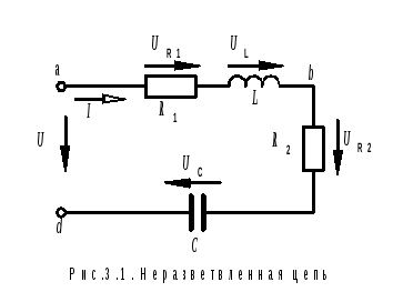
We write the equation of the second Kirchhoff law in vector form: the voltage applied to the circuit is equal to the sum of the voltages on all elements:
Ū = Ū R1 + Ū L+ Ū R2 + Ū C(3.1)
The sum of the stresses on the right side of the equation is written in the order in which, when going around the contour from the point A (of the first input terminal) to the point d (second input terminal) matched elements are encountered. We will postpone vectors in the same order. When constructing a diagram, we bypass the circuit in the direction of the current. We pay attention to the fact that the direction of the voltage arrow on each element of the circuit coincides with the direction of the current arrow.
We start plotting the diagram with the current vector, because in a series circuit, the current is common to all elements (Fig. 3.2, a).
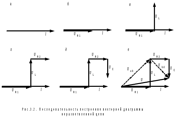
The first element that we meet when bypassing the circuit is active resistance. R 1 . Voltage vector on its clamps Ū R 1 is directed along the current vector Ī , combining the beginnings of these two vectors (Fig. 3.2, b). The next element is inductance L . Voltage Ū L on it according to equation 3.1 we must add to the voltage Ū R1. Therefore, the beginning of the vector Ū L is combined with the end of the vector Ū R 1 and in accordance with clause 2.2. we direct it upwards - towards the advance of the current (Fig. 3.2, c). By the end of the vector Ū L add vector Ū R 2 , directing it parallel to the current vector Ī (Fig. 3.2, d).
The last vector is Ū C is attached to the end of the vector Ū R 2 , directing it in the direction of lagging behind the current, i.e. down (Fig. 3.2, e). Vector Ū drawn from the beginning of the vector Ū R 1 to end of vector Ū C, and equal to the sum of all four vectors, determines the input voltage of the circuit (Fig. 3.2, e).
The resulting vector diagram allows you to determine the stresses in individual sections electrical circuit. For example, the voltage between points a And b the sum of the voltages on the active resistance R 1 and inductance L , so the vector Ū ab , directed from the beginning of the vector Ū R 1 to end of vector Ū L (shown by dotted line). The vector Ū bd equal to the sum of vectors Ū R2 and Ū C.
Task 3.2. According to a given vector diagram (Fig. 3.3), draw a circuit for which it is built.
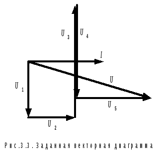
The diagram shows one current vector and five voltage vectors, which add up to the vector Ū :
Ū = Ū 1 + Ū 2 + Ū 3 + Ū 4 + Ū 5.
From this we conclude that the electrical circuit consists of five elements connected in series, through which the same current flows.
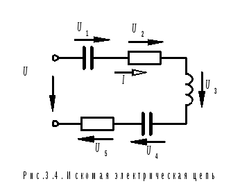
Voltage Ū 1 on the first element lags behind the current by 90º, therefore, this is a capacitance. The second element is active resistance, since the vector Ū 2 is parallel to the current vector Ī , is in phase with it. Voltage Ū 3 leads the current by 90º, hence the third element is inductance. The fourth element is capacity, because voltage Ū 4 lags the current by 90º (is in antiphase with the voltage Ū 3). And finally, the last element is active resistance again, because. the voltage on it is in phase with the current - vectors Ū 5 and Ī parallel and pointing in the same direction. The general view of the circuit is shown in Figure 3.4.
In active resistance, voltage and current are in phase, so the voltage vectors Ū R and current Ī directed in one direction (Fig. 2.1). They can lie on the same line or on parallel lines. In this case, a bunch of vectors Ū R and Ī may have an arbitrary direction, but in all cases the angle between the vectors is zero .
Note. In order for different vectors lying on the same straight line not to merge and be easily distinguishable from each other, we recommend that they be drawn at some rather small distance from each other.
2.2. Inductance
In an inductor, the current lags the voltage in phase by a quarter of a period. In a vector diagram, the angle between vectors Ū L and Ī is 90º. And here is a bunch of vectors Ū L and Ī can be oriented as you like, but their relative position is unchanged. When the diagram is rotated counterclockwise, the voltage vector is in front Ū L , followed by the current vector with a 90º lag Ī (fig.2.2).
2.3. Capacity
In a capacitance, the voltage lags the current by a quarter of a period. Angle between vectors Ū C and Ī is also equal to 90º, but here, when the diagram is rotated counterclockwise, the current vector comes first, followed by the voltage vector (Fig. 2.3).
The indicated mutual arrangement of the vectors on the diagrams takes place with the same directions of the voltage and current arrows on the circuit of the element under consideration.
3. Electrical circuit with series connection of elements
Task 3.1. It is required to build a vector diagram of a circuit consisting of series-connected elements (Fig. 3.1.).
We write the equation of the second Kirchhoff law in vector form: the voltage applied to the circuit is equal to the sum of the voltages on all elements:
Ū = Ū R1 + Ū L+ Ū R2 + Ū C(3.1)
The sum of the stresses on the right side of the equation is written in the order in which, when going around the contour from the point A (of the first input terminal) to the point d (second input terminal) matched elements are encountered. We will postpone vectors in the same order. When constructing a diagram, we bypass the circuit in the direction of the current. We pay attention to the fact that the direction of the voltage arrow on each element of the circuit coincides with the direction of the current arrow.
We start plotting the diagram with the current vector, because in a series circuit, the current is common to all elements (Fig. 3.2, a).
The first element that we meet when bypassing the circuit is active resistance. R 1 . Voltage vector on its clamps Ū R 1 is directed along the current vector Ī , combining the beginnings of these two vectors (Fig. 3.2, b). The next element is inductance L . Voltage Ū L on it according to equation 3.1 we must add to the voltage Ū R1. Therefore, the beginning of the vector Ū L is combined with the end of the vector Ū R 1 and in accordance with clause 2.2. we direct it upwards - towards the advance of the current (Fig. 3.2, c). By the end of the vector Ū L add vector Ū R 2 , directing it parallel to the current vector Ī (Fig. 3.2, d).
The last vector is Ū C is attached to the end of the vector Ū R 2 , directing it in the direction of lagging behind the current, i.e. down (Fig. 3.2, e). Vector Ū drawn from the beginning of the vector Ū R 1 to end of vector Ū C, and equal to the sum of all four vectors, determines the input voltage of the circuit (Fig. 3.2, e).
The resulting vector diagram allows you to determine the voltage in individual sections of the electrical circuit. For example, the voltage between points a And b the sum of the voltages on the active resistance R 1 and inductance L , so the vector Ū ab , directed from the beginning of the vector Ū R 1 to end of vector Ū L (shown by dotted line). The vector Ū bd equal to the sum of vectors Ū R2 and Ū C.
Task 3.2. According to a given vector diagram (Fig. 3.3), draw a circuit for which it is built.
The diagram shows one current vector and five voltage vectors, which add up to the vector Ū :
Ū = Ū 1 + Ū 2 + Ū 3 + Ū 4 + Ū 5.
From this we conclude that the electrical circuit consists of five elements connected in series, through which the same current flows.
Voltage Ū 1 on the first element lags behind the current by 90º, therefore, this is a capacitance. The second element is active resistance, since the vector Ū 2 is parallel to the current vector Ī , is in phase with it. Voltage Ū 3 leads the current by 90º, hence the third element is inductance. The fourth element is capacity, because voltage Ū 4 lags the current by 90º (is in antiphase with the voltage Ū 3). And finally, the last element is active resistance again, because. the voltage on it is in phase with the current - vectors Ū 5 and Ī parallel and pointing in the same direction. The general view of the circuit is shown in Figure 3.4.
stress triangle And resistance triangle,:
Series circuit R, C on alternating current: current and voltage vector diagram, voltage triangle. Ohm's law in complex form.
if current flows in such a branch, then the voltage drop will be the sum of:
Where ; the above equation can be associated with the expression: , which is clearly demonstrated by vector diagrams, respectively called stress triangle And resistance triangle,:
Ohm's law in complex form:
Serial circuit R, L, C on alternating current: vector diagram of current and voltages. Reactance chains. Stress resonance.
voltage drop across the circuit: , where: , and . Depending on the ratio of the values and, three different cases are possible:
The circuit is dominated by inductance, i.e. , and consequently . This mode corresponds to the vector diagram on figure a.
The circuit is dominated by capacitance, i.e. , which means . This case is reflected in the vector diagram on figure b.
The case of stress resonance ( drawing in).
Stress resonance condition: , at which . With voltage resonance or modes close to it, the current in the circuit increases sharply. In the theoretical case, at R=0, its value tends to infinity. According to the increase in current, the voltages on the inductive and capacitive elements increase, which can many times exceed the voltage of the power source. The physical essence of resonance lies in the periodic exchange of energy between magnetic field inductor and the electric field of the capacitor, and the sum of the energies of the fields remains constant.
- resonance curves the dependences of current and voltage on frequency are called:
Branched AC electrical circuits: complex conductivity of the series branch R, L, conductance triangle, equivalent parallel circuit with conductivities.
- impedance such a chain: ;
- admittance: ;
When depicting a triangle of conductivities on a complex area, active, inductive and total conductivities are laid aside: (see Fig.) and
sequential circuit connections R and L can be replaced by parallel by converting the current through the circuit as the sum of the active and reactive current:
it is convenient to make calculations of branched circuits, leading them to equivalent parallel:
Parallel electrical circuit from a capacitor and an inductor: an equivalent parallel circuit, a vector diagram of currents. Resonance of currents.
The complex of the total current through such a branch: ;
The conductivity of such a circuit is:
Three different cases are possible depending on the ratio of the quantities and.
The circuit is dominated by inductance, i.e. , and consequently, . This mode corresponds to the vector diagram on figure a .
The circuit is dominated by capacitance, i.e. , which means . This case is illustrated by the vector diagram on figure b .
I - case of resonance of currents ( drawing in ).
Current resonance condition or . Thus, at current resonance, the input conductivity of the circuit is minimal, and the input resistance, on the contrary, is maximum. In particular, if there is no resistor in the circuit in the figure R its input impedance in the resonance mode tends to infinity, i.e. at resonance of currents, the current at the input of the circuit is minimal.
The above resonance condition is valid only for the simplest circuits with series or parallel connection inductive and capacitive elements.
Power in an AC electrical circuit: instantaneous power in the elements R, L, C. Reactive power of inductance and capacitance. Power Triangle. Active, reactive, apparent and complex power of the entire circuit.
The rate of transfer or transformation of energy is called power :
- instantaneous power value in an electric circuit: , taking the initial phase of the voltage as zero, and the phase shift between voltage and current as , we get:
Thus, the instantaneous power has a constant component and a harmonic component, the angular frequency of which is 2 times greater than the angular frequency of voltage and current.
When the instantaneous power is negative, which is the case (see figure), when u And i different signs, i.e. when the directions of voltage and current in the two-terminal are opposite, energy is returned from the two-terminal to the power supply.
Such a return of energy to the source occurs due to the fact that energy is periodically stored in magnetic and electric fields respectively inductive and capacitive elements, which are part of the two-terminal network;
The energy given off by the source to the two-terminal network during the time t is equal to .
Average value for the period instant power called active power: , [W]; Considering that , we get: . Active power, consumed by a passive two-terminal network, cannot be negative (otherwise, the two-terminal network will generate energy), therefore, i.e. at the input of a passive two-terminal network. Happening P=0, is theoretically possible for a two-terminal network that does not have active resistances, but contains only ideal inductive and capacitive elements.
- power across the resistor(ideal active resistance) only active is consumed, because current and voltage are in phase:
- power on the inductor(ideal inductance) not consumed:
Because the current lags the voltage in phase by , then: ; In section 1-2 (see Fig.), the energy stored in the magnetic field of the coil increases. On section 2-3 - decreases, returning to the source.
- capacitor power(ideal capacity) is also not consumed:
The current here is ahead of the voltage, so , and . Thus, in the inductor and capacitor there is no irreversible conversion of energy into other forms of energy. Here only the circulation of energy takes place: Electric Energy stored in the magnetic field of the coil or electric field capacitor for a quarter of the period, and over the next quarter of the period, the energy is again returned to the network. Because of this, the inductor and capacitor are called reactive elements, and their resistances X L , a , then the complex full power:
- power triangle– mapping of complex power values on the complex plane (for we have the following mapping).
To simplify the analysis and calculation of AC circuits, it is advisable to use vectors.
In electrical engineering, vectors depict sinusoidally changing EMF, voltages and currents, but unlike the vectors that depict forces and speeds in mechanics, these vectors rotate with a constant angular frequency ω and do not indicate the direction of action.
Let us assume that the radius vector OA (Fig. 2.3, a), which, on a certain scale, is the amplitude value of the EMF E t, rotates with a constant angular frequency ω \u003d 2 πf counterclock-wise. The projection of the OA vector onto vertical axis(axis at) will be equal to
O a \u003d OA sin α.
Having expressed OA through the amplitude value of the EMF E T and α through ωt, we obtain the expression for the instantaneous value of the EMF, which changes sinusoidally:
e \u003d E t sin ωt.
The plot of instantaneous EMF values is shown in fig. 2.3b. The moment of time when the radius vector coincides with the horizontal axis (x-axis) is chosen as the origin.
Rice. 2.3. Rotating vectors (a) and plot of instantaneous sinusoidal EMF values (b)
If at the moment t=0 radius vector OA coincides with the line at an angle ψ to the x-axis, then the projection Oa" and, therefore, the emf will be respectively equal
Oa" \u003d OA "sin (ωt + ψ), e \u003d Em sin (ωt + ψ).
Similarly, voltage and current can be represented as vectors rotating counterclockwise with a constant angular frequency ω.
Circuit calculation sinusoidal current produce in the effective values of EMF, voltages and currents. In this case, the summation E, U, I easier to implement using rotating vectors, instead of adding the instantaneous values e, And, i, determine the effective values of the resulting E, U, I integration of harmonic functions. The adequacy of these actions can be justified as follows.
Let's assume that in some node of the AC circuit (Fig. 2.4, a) the values \u200b\u200bof the currents i 1 and i 2 are known:
i 1 \u003d I 1m sin (ωt + ψ 1);
i 2 \u003d I 2 m sin (ωt + ψ 2).
It is required to determine the current i.
Based on Kirchhoff's first law, the instantaneous value of the current
i \u003d i 1 + i 2,
i \u003d I 1m sin (ωt + ψ 1) + I 2m sin (ωt + ψ 2).
Current i can be determined analytically by trigonometric transformations or graphically by adding graphs of instantaneous values of currents i 1 and i 2, as is done in fig. 2.4, b. The resulting current also changes sinusoidally and in accordance with fig. 2.4, b

Rice. 2.4. Addition of sinusoidal currents using vectors (a): plots of instantaneous current values (b)
i = I m sin (ωt + ψ).
It is much easier to add the currents i 1 and i 2 if we represent the amplitudes of the currents as vectors and add them according to the parallelogram rule. On fig. 2.4, and the amplitudes of the currents I 1 m and I 2 m are shown as vectors at the angles of the initial phases ψ 1 and ψ 2 relative to the x-axis. After time t, the vectors will rotate through the angle α = ωt. The projections of the amplitudes on the y-axis will be
i 1 \u003d I 1 m sin (ωt + ψ 1);
i 2 \u003d I 2 m sin (ωt + ψ 2).
Adding the vectors I 1 m and I 2 m according to the parallelogram rule (see Fig. 2.4, a), we obtain the amplitude of the resulting current I m. The sum of the projections of currents I 1 m and I 2 m is equal to the projection of the resulting current I m:
i = i1 + i2.
The resulting expression corresponds to the first Kirchhoff law for the considered chain node (see Fig. 2.4, a). From fig. 2.4. and it is clear that the mutual arrangement of the vectors I 1 m, I 2 m and I m at any moment of time remains unchanged, since they rotate with a constant angular frequency ω. Similarly, you can determine the sum of several voltages or EMF that change sinusoidally with the same frequency. For example, three voltages act in a series alternating current circuit:
u 1 \u003d U 1 m sin (ωt + ψ 1);
u 2 \u003d U 2 m sin (ωt + ψ 2);
u 3 \u003d U 3m sin (ωt + ψ 3).
The sum u \u003d u 1 + u 2 + u 3 voltages can be determined by adding the vectors of their amplitudes (Fig. 2.5)

Fig 2.5. Vector stress diagram
Ūm = Ū1m + Ū2m + Ū3m
and subsequent recording of the resulting voltage u = U m sin (ωt + ψ).
The set of several rotating vectors corresponding to the equations of an electrical circuit is called a vector diagram.
Usually, vector diagrams are built not for amplitude, but for effective values. Effective value vectors are different from vectors amplitude values only in scale, because
I = I m / .
When constructing vector diagrams, one of the initial vectors is usually placed on the plane arbitrarily, while the remaining vectors are placed at appropriate angles to the original one. In this case, in the vast majority of cases, it is possible to do without plotting the coordinate axes X And at.
 (1 ratings, on average: 5,00 out of 5)

