Active resistance
Consider the following circuit.
It consists of a source AC voltage, connecting wires and some load. Moreover, the load inductance is very small, and the resistance R is very high. We used to call this load resistance. Now we will call it active resistance.
Active resistance
Resistance R is called active, because if there is a load with such resistance in the circuit, the circuit will absorb the energy coming from the generator. We will assume that the voltage at the circuit terminals obeys the harmonic law:
U = Um*cos(ω*t).
We can calculate the instantaneous current value using Ohm's law; it will be proportional to the instantaneous voltage value.
I = u/R = Um*cos(ω*t)/R = Im*cos(ω*t).
Let us conclude: in a conductor with active resistance there is no phase difference between voltage and current fluctuations.
RMS current value
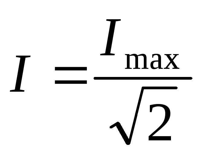
The amplitude of the current is determined by the following formula:
The average value of the squared current over a period is calculated using the following formula:
Here Im is the amplitude of the current fluctuation. If we now calculate Square root from the average value of the square of the current, we obtain a value called the effective value of the force alternating current.
The letter I is used to denote the effective current value. That is, in the form of a formula it will look like this:
I = √(i^2) = Im/√2.
The effective value of the alternating current will be equal to the strength of the direct current at which, over the same period of time, the same amount of heat will be released in the conductor in question as with alternating current. To determine the effective voltage value, the following formula is used.
U = √(u^2) = Um/√2.
Now let's substitute effective values current and voltage, in the expression Im = Um/R. We get:
This expression is Ohm's law for a section of a circuit with a resistor through which alternating current flows. As in the case of mechanical vibrations, in alternating current we will be of little interest in the values of current strength and voltage at any particular moment in time. It will be much more important to know General characteristics vibrations - such as amplitude, frequency, period, effective values of current and voltage.
By the way, it is worth noting that voltmeters and ammeters designed for alternating current record exactly the effective values of voltage and current.
Another advantage of real values over instantaneous values is that they can be immediately used to calculate the value medium power P AC.
A) Active resistance R, r is an idealized circuit element in which irreversible transformations of electrical energy into heat occur:
 A.
A.
b) Inductance L is an idealized circuit element, which is characterized by the ability to accumulate magnetic field energy. The inductance is numerically equal to the ratio of the flux linkage to the current by which this flux linkage is caused:
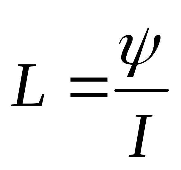 ,
(3.6)
,
(3.6)
Where  - inductor coupling flux,
N– number of coil turns,
F– magnetic flux.
 .
.
c) Capacity C – idealized element electrical circuit, which is characterized by the ability to accumulate electric field energy.
 ,
(3.7)
,
(3.7)
Where  – charge on the plates or plates of the capacitor,
 – potential difference between the capacitor plates.
Capacity C – does not depend on 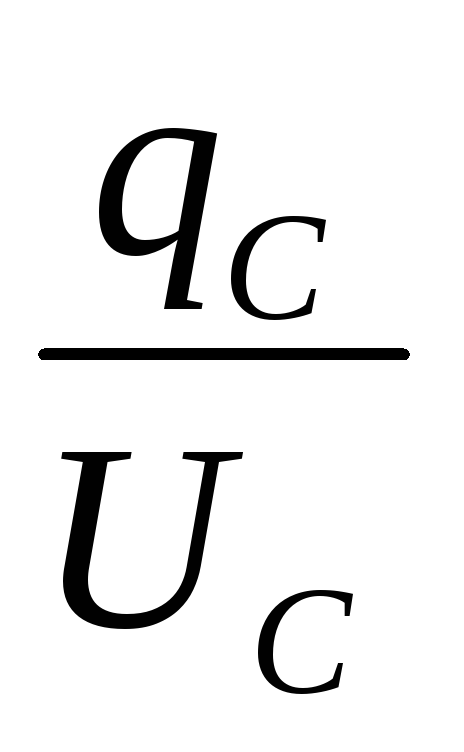 , but is determined by the size, shape of the capacitor, as well as the dielectric properties of the medium located between the plates of the capacitor.
 .
.
RMS value of alternating current
Oscillations arising under the influence of an external periodically changing EMF are called forced electromagnetic oscillations. Steady-state forced electromagnetic oscillations can be considered as the flow of alternating current in a circuit containing a resistor, inductor and capacitor.
In Fig. Figure 3.5 shows a graph of alternating sinusoidal current.

Rice. 3.5. AC graph
The effective value of the alternating current is equal to the value of the direct current, which, in a time equal to the period of the alternating current, releases in the same resistance the same amount of heat as the given current. Determined by formula 3.8.
 . (3.8)
Active, reactive and impedance in alternating current circuits
Current in active resistance
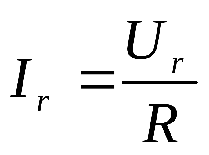 ,
(3.9)
,
(3.9)
Where I r , U r- effective values of current and voltage across active resistance R.
The phase shift between current and voltage across the resistor is zero (see Fig. 3.6).
Rice. 3.6. Vector diagram current and voltage across the resistor
Current in inductance
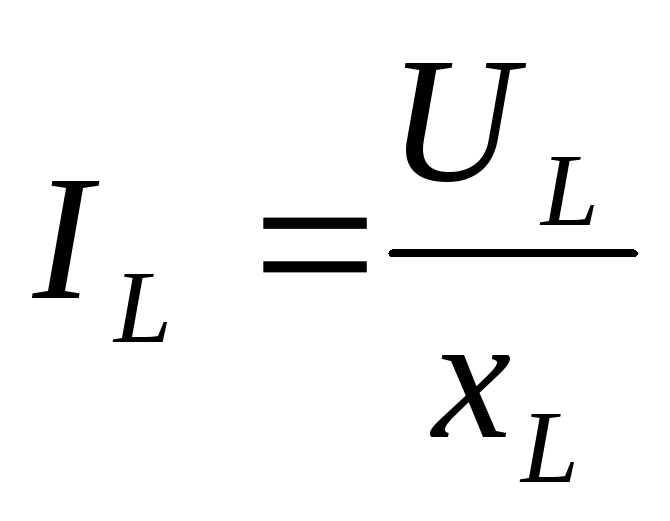 ,
(3.10)
,
(3.10)
Where I L , U L- effective values of current and voltage across the inductive reactance X L .
 ,
(3.11)
,
(3.11)
Where ω – cyclic frequency is zero, so when DC the inductor has no resistance.
LECTURE No. 3
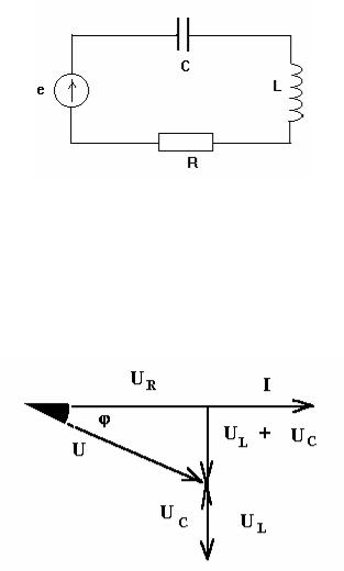
4. Electric circuit with active and inductive elements.
The circuit consists of elements whose properties are already known to us. Let's analyze the operation of this circuit.
Let the current in the circuit vary according to the law:
i = im sin t .
Then the voltage across the active resistance is determined by the formula:
uR = uRm sin t,
since in this section the current and voltage are in phase. Coil voltage:
uL = uLm sin (t + /2),
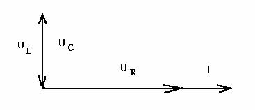
since the voltage across the inductor is ahead of the current in phase by an angle equal to /2. Let's construct a vector diagram for the circuit in question. First, we plot the current vector, then the voltage vector across the active resistance, which is in phase with the current vector. The voltage vector on the inductive element, advancing the current vector by an angle of /2, will be attached to the end of the voltage vector on the active resistance.
Vectors U R , U L , U form a right triangle. Let us derive Ohm's law for this circuit. On
based on the Pythagorean theorem, for right triangle voltages we have:
U = (UR 2 + UL 2 )1/2.
But U R = IR, and U L = IX L, therefore
U = (I2 R2 + I2 XL 2 )1/2 =I(R2 + XL 2 )1/2 ,
whence Ohm's law follows for this circuit
I = U / (R2 + XL 2 )1/2.
Let us introduce the notation (R 2 + X L 2 ) 1/2 = Z, where Z is the total resistance of the circuit. Then Ohm's law will take the form:
Since the total resistance of the circuit Z is determined by the Pythagorean theorem, it corresponds to a resistance triangle:

Since when serial connection the voltages in the sections are directly proportional to the resistances, then the resistance triangle is similar to the voltage triangle.
The phase shift between current and voltage is determined from the resistance triangle:
tg = XL / R, cos = R / Z.
For series circuit Let's agree to count the angle from the current vector. Since the vector of the total voltage drop is shifted in phase relative to the current vector by an angle counterclockwise, this angle has a positive value.
The total instantaneous voltage in the circuit is determined by the formula:
u = um sin(t+),
The average or active power for a given circuit characterizes the energy consumption at the active resistance and, therefore,
P = UR I.
UR = Ucos.
Reactive power characterizes the intensity of energy exchange between the inductor and the source electrical energy:
Q = UL I
From the vector diagram it can be seen that
UL = Usin.
The concept of apparent power is used to estimate the maximum power electric machines. The total power of alternating current is the power that flows from the source to the consumer and is determined by the formula:
Part of this power in the consumer is converted into useful - active power, as a result of which we have mechanical movement, heat, light and so on.
The other part of the total power that does not go to useful action consumers, but only excites magnetic fields in them.
The relationship between the values of total, active and reactive powers is the same as between total, active and reactive voltages. If all sides of the voltage triangle are multiplied by the current I, then we get a new triangle - a power triangle, the hypotenuse of which is equal to the total power, the horizontal leg is active power, and the vertical leg - reactive power:
S = (P2 + Q2)1/2.
Measured full power in volt-amperes (VA). Instantaneous power is expressed by the relation:
p = ui = um im sin (t+) sin t = um im (sin t cos + sin cos t) sin t = um im (sin2 t cos + sin sin t cos t) = um im [ cos (1 - cos 2 t)/2 +
sin (sin 2 t)/2 ]= (um im /2) = UI cos - UI cos(2 t +).
Thus, instantaneous power in this case, it consists of UI cos - a constant component, and a sinusoidal component of double frequency. The energy process in a circuit containing L and R consists of two considered energy processes: firstly, energy is irreversibly transferred from the source to active resistance, where it is converted into other forms of energy; secondly, energy fluctuates between the source and magnetic field receiver The smaller cos, the greater the role these useless energy fluctuations play.
5. Electric circuit with active and capacitive elements.
Study methodology R-C circuits similar studying R-L chains.
We set the current i = i m sin t. Then the voltage across the active resistance is:
uR = uRm sin t.
The voltage on the capacitor lags in phase with the current by an angle / 2:
uC = uCm sin (t - /2).
Let's build a vector diagram for this circuit:
From the vector diagram it follows that
U = (UR 2 + UC 2 )1/2.
But U R = IR, and U C = IX C, therefore
U = (I2 R2 + I2 XС 2 )1/2 =I(R2 + XС 2 )1/2 ,
I = U / (R2 + XC 2 )1/2.
Let us introduce the notation (R 2 + X C 2 ) 1/2 = Z, where Z is the total resistance of the circuit. Ohm's law for this circuit:
The location of its sides corresponds to the location of the sides of the stress triangle on the vector diagram. The phase shift in this case is negative, since the voltage lags in phase with the current:
tg = - XC / R, cos = R / Z.
In terms of energy, this circuit does not differ from a circuit with resistive and inductive elements
Average power is determined by the constant component of instantaneous power:
Reactive power characterizes the intensity of energy exchange between the capacitor and the source of electrical energy:
Q = UC I sin.
Because< 0 , то реактивная мощностьQ < 0 . Физически это означает, что когда емкость отдает энергию, индуктивность ее потребляет, если они находятся в одной цепи.
The power triangle for the circuit under consideration has the form:
The relationship between these powers can be obtained from the triangle:
S = (P2 + Q2)1/2.
6. Electric circuit with active, inductive and capacitive elements.
An electrical circuit with a series connection of active, inductive and capacitive elements called a series oscillatory circuit.
Circuit current:
Voltage across active resistance:
Inductor voltage:
i = im sin t.
uR = uRm sin t.
uL = uLm sin (t + /2).
Capacitor voltage:
uC = uCm sin (t - /2).
Let's construct a vector diagram provided that X L< X C , то есть U L =IX L < U C =IX C .
The resulting voltage vector U closes the polygon of vectors U R , U L , U C . The vector(U L + U C) determines the voltage across the inductance and capacitance. As can be seen from the diagram, this voltage can be less than the voltage across the inductance and capacitance. This is explained by the process of energy exchange between inductance and capacitance.
Let us obtain Ohm's law for the circuit under consideration. The vector modulus (U L + U C ) is calculated as the difference in effective values (U L - U C ), from the vector diagram it follows that
U = (UR 2 + (UL - UC )2 )1/2.
But UR = IR, and UC = IXC and UL = IXL, therefore
U = I (R2 + (XL - XC )2 )1/2 ,
I = U / (R2 + XC 2 )1/2.
Let us introduce the notation (R 2 + (X L - X C) 2) 1/2 = Z, where Z is the total resistance of the circuit. Ohm's law for this circuit:
The difference between inductive and capacitive reactance (X L - X C) is called the reactance of the circuit.

The resistance triangle for this circuit looks like:
When X L > X C the reactance is positive and the resistance is active-inductive in nature. At X L< X С реактивное сопротивление отрицательно и сопротивление цепи носит активноемкостной характер. Знак сдвига фаз между током и напряжением получим автоматически, так как реактивное сопротивление - величина алгебраическая:
Thus, at X L X C, either inductive or capacitive reactance predominates, that is, from an energy point of view, the circuit cR, L and C is reduced to the circuit cR, L or R, C.
Instant Power:
p = ui = UI cos - UI cos (2 t +).
The sign is determined from tg = X/R. The active, reactive and apparent power of such a circuit is determined by the equalities:
P = UI cos, Q = U I sin, S = UI = (P2 + Q2)1/2.
The power triangle for this circuit is:
Power factor.
On modern industrial enterprises Most consumers of AC electrical energy are active-inductive loads in the form asynchronous electric motors, power transformers, welding transformers, converters and so on. In such a load, as a result of the flow of alternating current, an emf is induced. self-induction, causing a phase shift between current and voltage. This phase shift usually increases and acos decreases at low load. For example, if the cos of AC motors at full load is 0.75 - 0.8, then at light load it decreases to
If the power consumed by all receivers in these circuits is quite definite, then at a constant voltage at the receiver terminals their current is:
I = P / (Ucos)
With a decrease in cos, the load current of power plants and substations will increase at the same output power.
At the same time electric generators, transformers and power lines are designed for
certain voltage and current. The increase in consumer current with a decrease in cos should not exceed certain limits, since the generators feeding them are designed for a certain rated power Snom = Unom Inom, as a result of which they should not be overloaded. In order for the generator current not to exceed the rated value when the consumer's cos decreases, it is necessary to reduce its active power. Thus, a decrease in cos of consumers causes incomplete use of power synchronous generators, transformers and power lines. They are loaded uselessly due to inductive reactive current
![]()
cos, which characterizes the use of installed power, is often called power factor.
Power factor is the ratio of active power to total power: cos = P/S
Power factor shows how much electrical energy is irreversibly converted into other types of energy and, in particular, used to perform useful work. A cos of 0.85 - 0.9 is considered normal. If the power factor is low, the enterprises consuming electricity are fined; if the power factor is high, the enterprises are awarded bonuses.
To improve the power factor, a number of measures are taken:
1. AC motors, which are loaded relatively lightly, are replaced with motors of lower power; 2. capacitors are connected in parallel with the receivers.
PARALLEL CONNECTION OF AC RECEIVERS.
Consider an electrical circuit consisting of two receivers connected in parallel to the terminals of a sinusoidal voltage source
u = um sin t.
In the first receiver, elements R1 and L are connected in series, in the second, R2 and C, respectively. Both receivers are under the influence of the same common voltage.
Electrical circuits of this type are called parallel oscillatory circuits.
Expressions for the instantaneous values of currents in the first and second branches of the circuit under consideration are inductive and capacitive in nature, respectively:
i1 = i1m sin(t-1); i2 = i2m sin(t +2);
The effective value of the current and the phase angle between the current and voltage are determined from the following expressions:
for the first branch
I1 = U / (R1 2 + XL 2 )1/2 ; cos1 = R1 / (R1 2 + XL 2 )1/2 ;
for the second branch
I2 = U / (R2 2 + XC 2 )1/2 ; cos2 = R2 / (R2 2 + XC 2 )1/2 ;
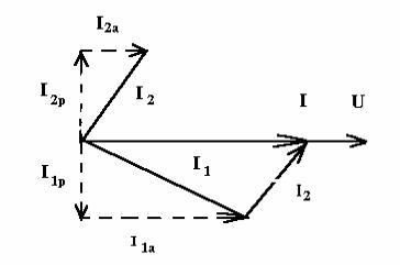
Knowing the currents in the branches, it is impossible to determine the value of the current in the unbranched part of the circuit by simply adding the currents i1 and i2, since in this case it is necessary to take into account their phase angles 1 and 2. Therefore, the current in the unbranched part of the circuit is defined as the geometric sum of the currents in the branches. Let's construct the corresponding vector diagram. When constructing a vector diagram of currents, it is customary to take the voltage vector as the initial vector. The current vectors in the branches are directed taking into account their phase shift relative to the voltage vector. The vector diagram looks like:
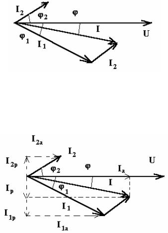
From this vector diagram, the magnitude of the current in the unbranched part of the circuit and the phase shift angle between the current and voltage in the unbranched part of the circuit are determined.
Vector diagram method, like any other graphic method, does not make it possible to obtain high accuracy. These same quantities can also be determined analytically. To do this, the concepts of active and reactive current components are introduced for a branch with a series connection of active and reactive elements. The active component of the current is in phase with the applied voltage. The reactive component of the current is shifted relative to the applied voltage by an angle /2:
The active component of the current in the unbranched part of the circuit is equal to the sum of the active component currents in each branch:
I a= I 1a+ I 2a.
Where I1a = I1 cos1, I2a = I2 cos2.
The reactive component of the current in the first branch lags in phase from the voltage by /2, and the reactive component of the current in the second branch
leads the voltage by /2. Thus, the reactive component of the current in the unbranched part of the circuit is equal to the difference in the reactive currents in the first and second branches, that is
Iр = I1р - I2р.
Where I1р = I1 sin1, I2a = I2 sin2.
The expression for the total current in the unbranched part of the circuit has the form
I = (Ia 2 + Iр 2) 1/2.
The phase shift angle, as follows from the vector diagram, is determined by the relation:
tg = Iр / Ia
In the general case, when n power receivers are connected in parallel:
I aI Rn, I pI LnI Cn.
RESONANCE PHENOMENA IN AC CIRCUITS.
In electrical engineering, the resonant mode of operation of alternating current circuits is understood as a mode in which the resistance of the circuit is purely active. In relation to the power source, the circuit elements behave in resonant mode as active resistance, so the current and voltage in the unbranched part of the circuit are in phase.
The reactive power of the circuit is equal to zero.
Two main cases of resonance are possible: when the reactive elements of the circuit are connected in series with the source, voltage resonance is possible, and when parallel connection- resonance of currents.
Voltage resonance. Voltage resonance is a phenomenon in a circuit with a series connection of elements when the current in the circuit is in phase with the source voltage.
Let us find the conditions for voltage resonance. In order for the current in the circuit to be in phase with the voltage, the reactance must be zero, since
tg = X / R = (XL - XC) / R.
Thus, the condition for voltage resonance is the equality reactance circuit zero, or
XL = XC.
But X L = L, aX C = 1 / C, where is the frequency of the power source. As a result, we can write:
Solving this equation relatively we find:
1 / (LC)1/2 =0 .
At voltage resonance, the source frequency is equal to the natural frequency of the circuit. The voltage resonance corresponds to the vector diagram:
Based on this diagram and Ohm's law for this circuit, we will formulate the signs of voltage resonance.
1. The total resistance of the circuit is minimal and purely active.
2. The current in the circuit is in phase with the source voltage and reaches its maximum value. 3. The voltage on the inductor is equal to the voltage on the capacitor and each individually can be many times higher than the voltage at the terminals of the entire circuit (10 times). Therefore, resonance when elements are connected in series is called voltage resonance.
The voltage resonance mode can be obtained by changing the frequency of the source voltage while keeping the parameters of the oscillatory circuit elements unchanged or by changing the parameters of the oscillatory circuit elements.
In electrical power devices, in most cases, voltage resonance is an undesirable phenomenon associated with the unexpected occurrence of overvoltages, that is, voltages several times higher than the operating voltage of the installation, and fuses do not protect against the occurrence of these overvoltages.
Resonance of currents. In an electrical circuit, when two branches are connected in parallel, when elements R 1 and L are included in one branch, and R 2 and C in the other, a current resonance mode can be established, in which the current in the unbranched part of the circuit will be in phase with the voltage.
The resonant frequency is determined by the expression:
0 = (1 / LC)1/2 ((L/C - R1 2 )/(L/C - R2 2 ))1/2 .
It follows that the state of resonance of currents in the circuit can be obtained by changing the source frequency or changing the circuit parameters L, C, R 1, R 2. The vector diagram corresponding to the current resonance has the form:
At resonance of currents reactive current closes in a ring formed by inductance and capacitance, and the wires connecting the oscillatory circuit to the energy source, and the source itself, are completely unloaded from reactive current.
In the current resonance mode, the circuit in question behaves in relation to the power source as if it consists only of elements with active conductivity. In reality, currents can flow in parallel branches with reactive elements, even exceeding full current flowing in the power source. But these currents are always opposite in phase to each other. This means that every quarter of a period there is an exchange of energy between the magnetic field of the inductor and electric field capacitor, which is supported by the voltage of the power source.
With current resonance, the currents in the branches can exceed the current in the unbranched part of the circuit, not only at resonance, but also as it approaches it. Therefore, resonance when elements are connected in parallel is called current resonance.
Current resonance, unlike voltage resonance, is a phenomenon that is safe for electrical installations. Large currents in branches, when currents resonate, they arise only if large reactive conductivities of the branches are created - large capacitor banks and powerful reactive coils are installed.
 (1 ratings, on average: 5,00 out of 5)

