We write Ohm's law in complex form on a capacitive element
2.4.2. Ohm's and Kirchhoff's laws in complex form
Ohm's law in complex form:
Ỉ=Ủ/ Z or Ỉ= Y∙Ủ, (2.26)
where Ỉ is the current flowing in electrical circuit,
Ủ – tension. applied to an electrical circuit,
Y is the complex conductivity of the electrical circuit,
Z is the complex resistance of the electric circuit.
Kirchhoff's first law. The sum of the currents in the wires converging in the node of the electrical circuit is zero:
Kirchhoff's second law. The sum of complex e.m.f. or voltages acting in a closed circuit is equal to the sum of the voltage drops on the elements of this circuit.
 (2.28)
Ohm's and Kirchhoff's laws are valid for both instantaneous and effective values emf voltages and currents.
Operating (effective or root-mean-square voltage) is determined by the expression:
 ,
(2.29)
,
(2.29)
where T is the period of voltage fluctuations, equal to 1/f,
f is the frequency of voltage fluctuations.
With a strictly sinusoidal oscillation mode, the operating voltage is: U=Um/ 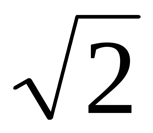 ,
(2.30)
,
(2.30)
where Um is the maximum voltage value u(t).
The effective emf values are determined similarly. and currents.
2.4.3. Construction of vector diagrams on a rotating complex plane
To facilitate the construction of vector diagrams on a rotating plane, it is necessary to remember the following basic provisions:
a) In a circuit with active resistance, current and voltage are in phase.
b) In an idealized circuit with only inductive resistance without losses, the voltage in phase leads the current by an angle equal to 90 degrees
c) In a purely capacitive, lossless circuit, the current leads the voltage in phase by +90 degrees.
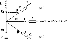
Fig.2.1.Mnemonic diagram explaining possible turns
radius-vectors with different inclusions of r-L-C elements.
When constructing vector diagrams, one must begin construction with a voltage or current vector common to the entire analyzed circuit. In particular, when switching on the circuit elements in series, one must begin with the construction of the current vector flowing through all the circuit elements. When the circuit elements are connected in parallel, the construction of a vector diagram must begin with the vector of the total applied voltage, and then build the vectors of the currents flowing through each of the branches of the electrical circuit. Possible phase shifts of voltage vectors in electrical circuits consisting of various combinations of r-L-C elements are shown in the mnemonic diagram (see Fig. 2.1.).
The radius vectors in the diagram and below are highlighted in bold or dots (dashes) above them.
2.4.4. Voltage resonance in a circuit consisting of an inductor and a capacitor connected in series
Consider examples of such an analysis under the assumption that the values of resistance, capacitance and inductance do not change with time and do not depend on the applied voltage and currents (see Fig. 2.2).
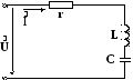
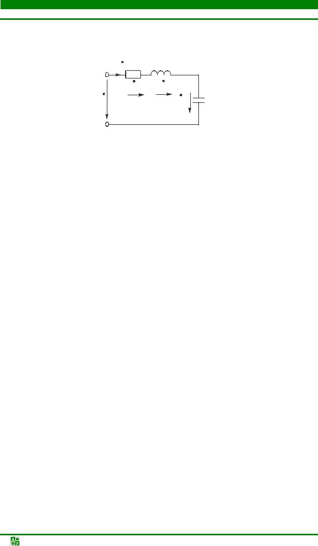
Fig. 2.2. Electric circuit of series-connected r-L-C-elements.
The processes occurring in the circuit under study (in accordance with the second Kirchhoff law) are described (with the constant values of the elements in time and their independence from the magnitude of the flowing current) by a linear integral-differential equation:
u(t)=ri(t)+Ldi(t)/dt+1/C ∫i(t)dt, (2.31)
where u(t) is AC voltage supplied from the source to the oscillatory circuit,
i(t) - alternating current flowing in the circuit,
L - inductance,
r- active resistance inductors,
C is the capacitance of the capacitor.
Resistance (r), inductance (L) and capacitance (C) form an oscillatory circuit in which voltage resonance is possible. The term "voltage resonance" implies that when X l \u003d Xc is equal, the alternating voltages on the circuit elements L and C increase by Q times compared to the voltage supplied from the source to the circuit. The value of Q is understood as the quality factor of the circuit, equal to Q \u003d Xc / r.
Under the assumptions made, equation (2.31) can be represented in the following form:
u(t)=i(t)*(r+j). (2.32)
Where does the expression for the complex resistance of the circuit come from
Z=r+j(Xl –Xc).
At voltage resonance, when X l \u003d Xc, Z=r, that is, the resistance of the circuit is active, and the current flowing through the circuit reaches a maximum value equal to i(t)max=u(t)/r.
In this case, the construction of a vector diagram must begin with a common current vector (Ỉ) for the circuit, then voltage vectors are built. At serial connection inductors and capacitances, the total reactance of the circuit X is equal to the algebraic difference between the inductive and capacitive resistances Xl and Xc. The voltage applied to such a circuit can be represented as the vector sum of the voltage drop vector across the active resistance (U r), which is in phase with the current vector; the vector of the voltage drop on the inductance (U l), leading the current in phase by an angle of 90 ° and the vector of the voltage drop on the capacitance (Uc), lagging in phase from the current vector by an angle of 90 °. In this case, the following cases are possible:
a) The inductive resistance is greater than the capacitive one (X l>X C). In this case, the input voltage will lead the current in phase by an angle φ (see Fig. 2.3.).
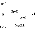
b) Capacitive resistance is greater than inductive (X l<Х с). При этом ток опережает напряжение на угол φ. Векторная диаграмма тока и напряжений показана на рис. 2.4.

Rice. 2.3 Fig. 2.4
V). Inductive resistance is equal to capacitive (X l \u003d Xc). Accordingly, the total reactance of the circuit (X) is zero, and the total resistance of the circuit Z=r, i.e. reaches its minimum value. In this case, the current will be in phase with the voltage, i.e. angle φ=0. The vector diagram of currents and voltages for this case is shown in fig. 2.5.
The phenomenon of voltage resonance also occurs in quartz resonators, which are widely used in self-oscillators.
U m = U m e j u ; I m = I m e j i = CU m e = CUm e j u e,
given that e j =j , -j= we get: I m = .
Let's move on to the complexes of effective values: I = U / X With ,
Where X
With =
- complex capacitive resistance.
The vector diagram on the complex plane of the current and voltage of the capacitive element is shown in fig. 1.10. 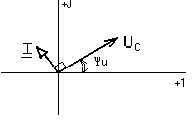
Rice. 1.10.
1.6. A complex method for calculating linear electrical circuits with sinusoidal currents
As you know, the calculation of any electrical circuit can be made on the basis of Kirchhoff's laws by compiling and solving a system of equations. Application of Kirchhoff's laws for instantaneous values of sinusoidal currents and voltages leads to differential equations. For example, for a circuit with active and inductive elements connected in series, the equation of Kirchhoff's second law has the form:
![]() .
.
The complete solution i(t) of this linear differential equation, as is known, is the sum of the particular solution determined by the form of the function u(t) and the general solution of the homogeneous differential equation obtained with u(t)=0. Current component at u(t)=0 can exist only due to energy reserves in the magnetic field of the inductive element and will decay due to energy dissipation on the active element. Thus, after a short period of time after switching on, a current remains in the circuit, determined only by a particular solution of the circuit equation. This current is called the steady state current. In what follows, we will analyze this mode. Suppose that the voltage applied to the circuit under study changes according to the law: u(t)=U 0 sin( t+ u) .
As shown earlier (see clause 1.5), in the active and inductive elements, the steady state current will also change according to a sinusoidal law: i(t)=I m sin( t+ ) .
The problem is reduced to finding the amplitude and initial phase of the current at a given frequency. If it is necessary to determine the branch currents or voltages in the circuit sections, the summation of the sinusoidal functions of time is required. This operation is associated with cumbersome and time-consuming calculations. The cumbersomeness of the calculations is due to the fact that the sinusoidal value at a given frequency is determined not by one, but by two quantities - amplitude and phase. Significant simplification is achieved when representing sinusoidal functions of time by complex numbers. The possibility of such a representation for sinusoidal currents and voltages was shown earlier (see paragraph 1.4.).
A method based on the representation of real sinusoidal functions of time by complex numbers is called the complex method. It is also called the symbolic method, since it is based on the symbolic representation of the function of time as a function of frequency. The complex method uses a very important property of the exponential function, which consists in the fact that differentiating the complex exponent in time is equivalent to multiplying it by j, and integration - division by j:
 ;
; ![]() .
.
As a result, all differential equations composed according to Kirchhoff's laws are replaced by algebraic equations in complex form. Solving these algebraic equations, we find complex currents and from them we pass to instantaneous values. Thus, the complex method greatly simplifies the calculations because it is a method of algebraization of differential equations.
1.7. Expression of Ohm's and Kirchhoff's laws in complex form
Considering active, inductive and capacitive elements in a sinusoidal current circuit, we introduced the concepts of active and reactive (inductive or capacitive) resistance. Summarizing, we call the ratio of the complex voltage to the complex current the complex resistance of the circuit Z:
![]() .
.
The module and the resistance argument are equal, respectively, to the ratio of effective values and the phase shift between current and voltage.
real and imaginary parts Z called active and reactive resistances. The reciprocal of the complex resistance is called the complex conductivity:
![]() .
.
Its modulus and argument are by definition the reciprocals of Z and . The real and imaginary parts of Y are called active and reactive conductivities. Let's establish a connection between active and reactive resistances and conductivities.
from here ![]() .
.
The introduction of complex resistances and conductances means the introduction of Ohm's law in a complex form for a steady sinusoidal mode: ![]() .
.
Unlike Ohm's law for direct current, here, in addition to the effective values of current and voltage, the phase shift between them is also taken into account.
Let us now write Kirchhoff's laws in a complex form.
The first Kirchhoff's law for knots in complex form is written as: .
Kirchhoff's second law for contours in complex form is written as: .
After the introduction of the concepts of complex resistance and the establishment of Ohm's and Kirchhoff's laws for complex currents and voltages of branches, there is no need to preliminarily compile systems of differential circuit equations with their subsequent transformation into algebraic equations for current and voltage complexes. When analyzing a circuit in a complex way, it is convenient to represent each element of the circuit with its complex resistance or conductivity, and currents and voltages - with the corresponding complexes of effective values. The result is a complex circuit equivalent circuit. In this diagram, each passive branch can be represented as a two-terminal network with complex resistance, and each active branch can be represented as a source with complex EMF and internal resistance.
Such an equivalent circuit will look like a resistive circuit, but instead of real values on the circuit there will be complex values of current, voltage, EMF and resistance.
TO 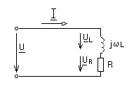
the complex nature of the quantities reflects the need to take into account the phase shift between sinusoidal currents and voltages in the steady state. The equations of state for complex equivalent circuits are drawn up in a similar way to resistive DC circuits. Therefore, when analyzing a circuit in a complex way, you can apply all those methods that are valid for direct current:
Methods for equivalent conversion of circuits (parallel and series connection of elements, star-delta conversion and vice versa, conversion of voltage and current sources);
Method of proportional values;
Method of nodal potentials;
Loop current method;
Equivalent generator method;
The principle of imposition, reciprocity.
Formally, the difference between the analysis in a complex way and the analysis of DC resistive circuits will consist only in the fact that the coefficients of all equations, as well as the variables, will be complex quantities.
Since each term in a complex equation can be represented by a vector, and the equation itself can be represented by the sum of vectors, the complex method allows you to accompany analytical calculations with visual graphic illustrations - vector diagrams.
Consider the use of a complex method for the calculation of specific circuits.
1.8. Real inductor in sinusoidal current circuit
Here is the total complex resistance of the coil: Z
=R+j
L
A real inductor, in addition to inductance, has the active resistance of the turns of the wire from which it is made. Therefore, the complex equivalent circuit will consist of inductive and active resistances connected in series, fig. 1.11.
According to Kirchhoff's second law, for complexes of effective stress values, the total stress
U= U L+ U R =jL I+R I=(jL+R) I=Z I
consists of active and reactive (inductive) components.
Rice. 1.11.
Modulus and resistance argument: Z=,
determine respectively the ratio of amplitudes and the phase shift between voltage and current. The current complex is ![]() ,
,
where u is the initial phase of the applied voltage.
Therefore, the expression for the instantaneous value of the sinusoidal current in a real inductor is:
![]() .
.
The current lags in phase from the voltage applied to the circuit by an angle , depending on the ratio between the active and inductive resistances of the coil.
The resulting complex relations can be depicted on a vector diagram, fig. 1.12. 
Rice. 1.12.
The vector of the current common to series-connected elements is taken as the initial one and is plotted in an arbitrary direction, usually horizontal.
Vector U R heading along the vector I , since it is in phase and the vector U L, leading the current vector by 90 o, we build perpendicular to the current counterclockwise. The geometric sum of these two vectors gives the vector U voltage applied to the inductor. Vector U phase leading vector I on the corner . If the initial voltage phase u given, it is possible to plot the axes of the complex coordinate system and, by means of geometric measurements, determine i and other parameters of interest to us.
However, it must be remembered that the representation of the total voltage at the terminals of a real inductor as the sum of the active and inductive components is formal and they do not exist in a real circuit and cannot be directly measured with a voltmeter.
1.9. Serial connection of a real inductor and a lossless capacitor in a sinusoidal current circuit
A series alternating current circuit with an inductive coil and a capacitor can be represented by a complex equivalent circuit of R, L, C elements, fig. 1.13. 
Rice. 1.13.
We write the applied voltage as the sum of the voltages on the circuit elements:
u= u R + u L + u C
or in complex form: U = U R + U L + U C .
LECTURE 7 NETWORK ANALYSIS WITH SERIAL
CONNECTING RECEIVERS
Lecture plan
4. Stress resonance
1. Basic laws of AC circuits
IN In AC circuits, Ohm's law holds for all values, Kirchhoff's laws - only for instantaneous and complex ones, which take into account phase relationships.
Kirchhoff's first law. Algebraic sum of instantaneous values of currents in the node:
∑ i k = 0 ,
k=1
or the algebraic sum of the complex values of the currents in the node is equal to zero:
∑ I k = 0 .
k=1
Kirchhoff's second law. The algebraic sum of the instantaneous voltage values at the receivers in the circuit is equal to the algebraic sum of the instantaneous values of the EMF acting in the same circuit:
Equations drawn up according to Kirchhoff's laws are called the equations of electrical state.
1. Basic laws of AC circuits
The circuit equivalent circuit with serial connection of receivers is shown in fig. 7.1.
To analyze the processes, we use the equation based on the second Kirchhoff law in complex form:
U = UR + UL + UC.
Substitute in this equation the stress values expressed according to Ohm's law:
U = R I+ j XL I− j XC I= [ R+ j(XL − XC ) ] I= Z I,
where Z is the complex resistance of the circuit.
It's obvious that
Z = R+ j(XL − XC ) = R+ j X,
where R is active resistance, X – reactance.
Ohm's law in complex form for a circuit with a serial connection of receivers:
U = ZI.
Reactance X can be positive or negative.
Reactance X > 0 if X L > X C . In this case, the chain
is inductive.
Reactance X< 0 , еслиX L < X C . Тогда цепь имеет емкостный характер.
2. Construction of a vector diagram
Usually, when constructing it, they are not tied to the complex plane, since only mutual arrangement vectors.
The construction of a vector diagram begins with a vector of magnitude common to a given circuit. When elements are connected in series,
LECTURE 7
2. Building a vector diagram
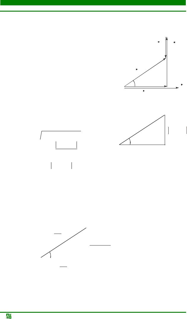
the quantity is the current. The type of diagram depends on the nature of the circuit. The construction of a vector diagram for a circuit that has an active-inductive character, i.e. X L\u003e X C and X\u003e 0, is shown in Fig. 7.2.
The input voltage is the sum of the voltages on three ideal elements, taking into account the phase shift. The voltage across the resistor is in phase with the current. The voltage on the inductive element leads the current by 90°, on the capacitive element it lags behind by 90°.
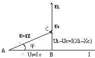
The triangle OAB obtained during the construction of the vector diagram is shown in Fig. 7.3.
Angle φ = ψu − ψi is the phase shift angle to-
ka and full voltage.
The OAB triangle makes it possible to operate with effective values for which Kirchhoff's laws are not fulfilled:
U = UR 2 + (UL − UC ) 2 ,
Arctg U L − U C ,
U R = Ucos ϕ , UL − UC = Usin ϕ .
UL-UC
O A UR
3. Triangles of resistance and power
If we divide all sides of the voltage triangle by current I, we get a resistance triangle similar to it (Fig. 7.4), where Z is the total resistance of the circuit, R is the active resistance, X is the reactance
ion, X L = L ω - inductive resistance, X C = | – capacitive resistance |
|||||||||||||||
tivlenie. | ||||||||||||||||
U − U | ||||||||||||||||
−X C | ||||||||||||||||
Ohm's law for effective values with a serial connection of receivers has the form:
LECTURE 7
3. Triangles of resistance and power
U = ZI.
From the properties of the resistance triangle we obtain the following relations:
Z \u003d R 2 +X 2 \u003d R 2 + (X L -X C) 2; ϕ =arctan | |||
R = Z cosϕ ;X = Z sinϕ . | |||
The angle ϕ depends on the ratio of the circuit resistances.
Comparison of the formulas for total and complex resistances allows us to conclude that the total resistance is the modulus of the complex. It can be seen from the resistance triangle that the argument of the complex resistance is the angle ϕ.
Therefore, we can write:
Z = R + jX = Z e j ϕ .
The impedance of any number of receivers connected in series
Z = (∑ R) 2 + (∑ XL − ∑ XC ) 2 .
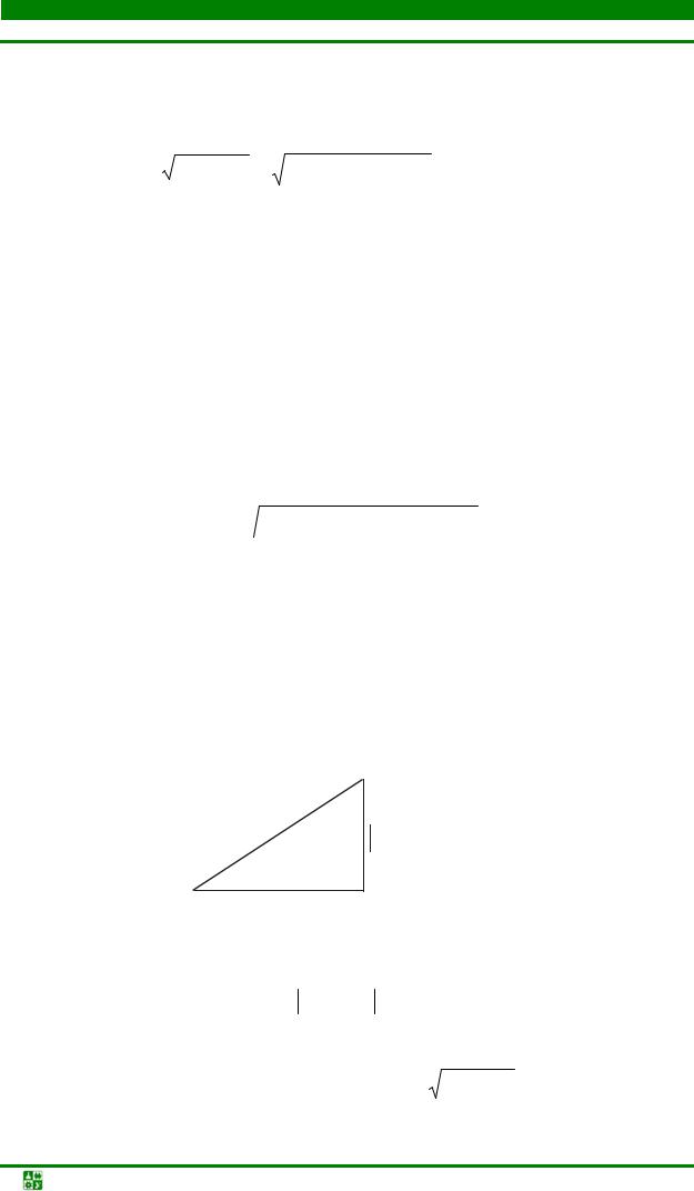
By multiplying all sides of the voltage triangle by the current, we get a power triangle (Fig. 7.5).
Active power
P = UR I= R I2 = U Icos ϕ
characterizes the energy that is transmitted in one direction from the generator to the receiver. It is connected with resistive elements.
U I= S
UL − UC I= Q
UR I=P
Reactive power Q \u003d U L - U C I \u003d X I 2 \u003d U I sinϕ characterizes
part of the energy that continuously circulates in the circuit and does not useful work. It is associated with reactive elements.
Full (apparent) power S \u003d U I \u003d P 2 + Q 2.
LECTURE 7
3. Triangles of resistance and power
Active power is measured in watts (W), reactive power is measured in reactive voltamperes (var), total power is measured in volt-amperes (V A).
4. Stress resonance
An inductive coil and a capacitor are mutually suppressive antipodes. When they fully compensate for the action of each other, in the chain on-
resonant mode is observed.
Voltage resonance occurs when inductive coils and capacitors are connected in series. Voltage resonance condition: input reactance X is zero.
Consider the resonance mode for the circuit, the equivalent circuit of which is shown in fig. 7.1.
At resonance
X =X L −X C =0 .
Hence X L = X C .
Since X L \u003d L ω, and X C \u003d C 1 ω, then at resonance L ω0 \u003d C 1 ω 0. Then LC ω0 2 = 1. It follows that to achieve voltage resonance in the circuit on
rice. 7.1 is possible by changing the inductance L, capacitance C and frequency ω. Cyclic resonant frequency
ω 0= | ||||||||||
Then the frequency | ||||||||||
f 0= | ||||||||||
At resonance, the impedance Z \u003d R 2 + X 2 \u003d R. The chain has |
||||||||||
purely active character. | (ω= ω0 ) | X = 0 | X L= X C, |
|||||||
resonant | ||||||||||
Z = R2 + X2 = R= Zmin , I= U | I max. | |||||||||
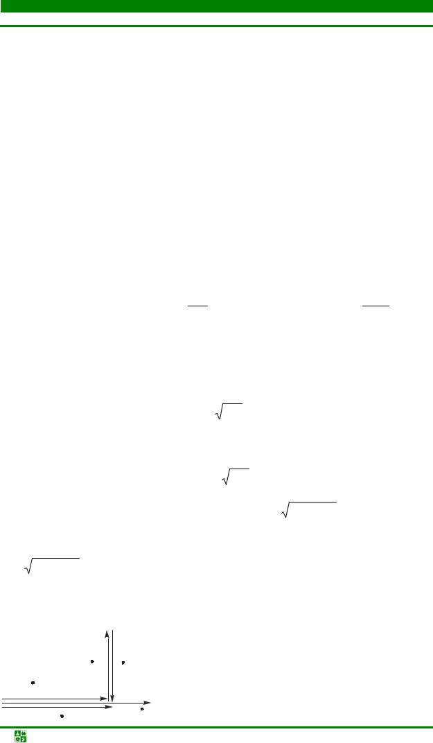
Let's build vector diagram(fig. 7.6). | ||||||||||
It is obvious that U = U R , | U L = − U C ,U L = U C , angle ϕ = 0 . | |||||||||
The circuit is purely active.
Voltage resonance value:
1. In electric power devices in U L U C most cases the phenomenon is undesirable,
![]()
LECTURE 7
4. Stress resonance
associated with sudden surges.
2. In electrical communication engineering (radio engineering, wire telephony), in automation, the phenomenon of voltage resonance is widely used to tune the circuit to a certain frequency.
Self-test questions
1. For what values electrical quantities Kirchhoff's laws are obeyed?
2. What is the modulus of complex resistance?
3. What is the argument of complex resistance?
4. How are active, reactive and complex resistances related?
5. How to calculate circuit impedance?
6. What determines the angle φ between voltage and current?
7. What power is consumed?
8. What energy is characterized by active power?
9. What kind of energy is reactive power?
10. What units are used to measure active, reactive and apparent power?
11. What is the stress resonance condition?
12. What is the meaning of stress resonance?
 (1 ratings, on average: 5,00 out of 5)

