Emergency program for calculating short circuit currents. Variant calculation of electrical quantities. Managing the screen when preparing a job
TKZ-3000- A set of programs for calculations electrical quantities in case of damage and calculation of relay protection settings.
The complex allows you to calculate electrical quantities in a three-phase symmetrical network of any voltage with a single longitudinal or transverse asymmetry and the settings of protection against ground faults.
Maximum capabilities of the complex:
- Network volume up to 3000 nodes and 7500 branches.
- The total number of inductively coupled branches is 2500.
- The number of branches in one group of inductively coupled branches is 20.
To use the complex you need an IBM PC/AT with free software RAM at least 540 kBytes and free space at least 3 MB on your hard drive.
Maintaining the functionality of important circuits such as lighting, electoral action also helps improve safety. To properly evaluate selectivity in this current range, the program has a wide range of measured selectivity values for many pairs safety devices. A currently neglected aspect of line design is the economic optimization of line cross-section. When designing a conductor, it is common to only consider its functionality in terms of current transferred, voltage drops, and resistance loops.
Using the complex, it is possible to obtain currents, voltages, ratios of currents to voltages (resistance) both in the form of symmetrical components and in the form of total phase or phase-to-phase quantities. For current protection against ground faults, detuning is carried out from a fixed short-circuit point and from the load, coordination with one or more protections, sensitivity testing, as well as modeling of the shutdown process during long-distance backup operation. The network management subsystem allows you to renumber network nodes, create a new network by merging two networks, and reconcile networks. The equivalent subsystem allows you to collapse the network to any number of nodes, as well as build a new network based on the resulting equivalent.
The only recognized economic indicator is the cost of management. However, with the ever-increasing price of electricity, it is also important to pay for the costs of electrical losses that occur during use. The cost of these losses can, under certain circumstances, be several times the cost of their own cable. Therefore, the program evaluates the so-called economical line cut based on these economic parameters so that the total costs, that is, the sum of the acquisition costs and the cost of losses, are as low as possible.
To run the complex, in the resulting folder, when unpacking the Tkz_.zip archive, find and run the file TKZ3000.BAT.
INPUT AND CORRECTION OF INITIAL DATA
Input of forward and reverse sequences is combined in one table. The parameters of the negative sequence (its topology is assumed to coincide with the topology of the direct sequence) should be entered only for those elements for which Z1 is not equal to Z2. Keep in mind that taking into account the differences in the reverse sequence increases the calculation time!
For forward and reverse sequences there are following types branches:
0 - simple branch
1 - branch with zero resistance
3 - transformer branch
4 - generator branch
5 - U-shaped equivalent circuit of a branch with capacitive conductivity
For branches of all types, the starting and ending nodes must be specified. For branches of all types except<1>, longitudinal active and (or) reactance resistances must be specified. For branches like<4>it is necessary to set additional E.M.F. (modulus in kV and angle), type<3>- transformation ratio, type<5>- capacitive conductivity. Any branch, except the generator branch, can be assigned an element (line, transformer) number; all branches belonging to the same element must have the same number. Types can be specified in the zero sequence<0>,<1>,<3>And<5>.
The parallel number can be specified within the range of 1-98.
When specifying a positive sequence circuit, use the following table as a guide:
The program always offers only accessories that match the product and control its quantity. In practice this means, for example, that it is not possible to select additional switches and auxiliary releases for circuit breaker mode than to physically fit into the cavity. Simply enter the data from the old breaker plate and the program will decipher the data and suggest an appropriate replacement. Here they are ready for use by any drawing program that can handle the document formats in use.
| Type |
E/K/B(c) |
|||||||
|
Wire capacity Variant calculation of electrical quantitiesOptimal deployment and use of all our product features precedes full project preparation and correct design solutions. We have prepared for you several tools that will make your job as a designer easier in your daily work in your industry. It fully complies with the switching technology requirements of the new standards. More than a thousand products can be found in the program database. The program can be developed one by one. three-pole connection diagram. Behind additional information please contact our technical department. For beam and mesh networks it calculates voltage drop, load distribution and currents short circuit in individual units and then checks the suitability of the cables and safety devices used. |
Here: + be sure to ask
- cannot be asked
[R],[X] - Ohm
[E.M.F.] - kV
labor coefficient = U(U1)/U(U2)
[cap. wire] - μSim (half the total capacitive conductance of the branch) without sign.
Negative sequence parameters are set only for those branches that have different resistances in the positive and negative sequence circuits.
The program is intended primarily for designers and compilers. You must have write permission to the directory in which the program is installed. . You can find the current price list by subscribing to our e-store. It allows you to search using various criteria. The product database is updated regularly and also includes links to recalled products that are being replaced with new ones. It also includes the ability to create custom bids.
Software to calculate optimal cooling of switchgears. The warming calculation in the switch is performed only in a few cases. This is very difficult process, and many designers replace it with an estimate of heat loss and an approximate determination possible ventilation, active cooling or possible heating. However, the estimate cannot be reliably determined. Unreliable operation of devices and equipment installed in switchgear, as well as their destruction due to high or low temperatures or water condensation in the distribution board.
These parameters are entered in the process of filling out the direct sequence table after pressing the F7 key (forward - reverse - forward switch).
When specifying the zero sequence circuit, you must be guided by the following table:
| Type | ||||||
|
capacity Prov. The program is designed to simplify this demanding work as much as possible and eliminate the possible risks of incorrectly defining and assessing temperature relationships in distribution boards. They provide accurate graphical display and monitoring of measured quantities on a computer, including configuration of device parameters. All waveforms can be exported to tables. It calculates voltage drop, load distribution and short-circuit currents for both spoke and node networks and performs subsequent suitability checks on the cables and protective devices used. The software is intended primarily for developers and engineers involved in calculations. |
Here: + be sure to ask
- cannot be asked
? may or may not be specified
[R],[X] - Ohm
labor coefficient = U(U1)/U(U2)
[cap. wire] - μSim (half of the total capacitance:
- conductivity of the branch) without sign.
- conductivity to ground) without sign.
Input and correction of inductively coupled branches (only in a zero-sequence circuit) in groups. Entry is possible in two ways:
1. First, the designations of the branches are entered and only after completing the entry of all branches of the group, by pressing the Tab key, they proceed to recording the own and mutual resistances of this group.
2. Input is made for each branch of the group, and its designation is first entered, and then the system prompts which resistances should be entered.
The method is selected by successively pressing the F5 key
Version 3 is the next generation of the program. It includes a new graphics and computing core, and a new user interface. The features included in the previous version 2 have been retained and new features have been added. Computational procedures have been updated to comply with current standards.
In addition, only basic calculations are given, which are evaluated by default. For specific cases You can also select other parameters for calculation. Load distribution in individual branches, checking the correct dimensions of safety devices and wires, checking that the cable is properly protected during overload and short circuit. Backup protection solution, monitoring the fault tolerance of assigned protection elements at the outputs in relation to the front installed protective devices at the inputs. Functions for evaluating the selectivity of switches according to verified selectivity tables. Single-phase unbalanced earth fault, calculation of short circuit current at a selected point in the network and short circuit currents in the network, calculation of short circuit impedance and touch voltage on non-living parts. Calculate the short circuit breaking time and check according to the standard requirements. Calculate the clustered and zero impedance components at the network node. Calculation results can be displayed either as absolute values or as complex numbers; the calculated impedances are not corrected by any coefficients.
- The beam network always takes into account the coexistence factor.
- The contribution of the engine is taken into account.
Inductively coupled branches without capacitive conduction to ground are type 2, and with capacitive conduction - 7.
The maximum number of branches in one group is 20.
ADDITIONAL INPUT SUBSYSTEM FEATURES
1. View data.
In this mode, you can view all types of network data. All data manipulations provided for in the input subsystem are possible, but do not lead to an actual change in the network model.
2. Checking network connectivity.
Connectivity is checked separately using direct, reverse (if any) and zero sequences. When a break is detected, all groups of nodes that are not connected to each other are output to a text file.
3. Checking the completeness of setting network parameters.
For direct and reverse sequences, the presence of R and X is checked for branches of type 0,3,4,5, E.M.F. for type 4, transformation ratio for type 3, capacitance for type 5.
For the zero sequence, in addition, the equality of the transformation coefficients specified for the same branch in the direct sequence circuit is checked. It is also checked that each branch is included in the corresponding sequence diagram only once, and, if it has inductive connections, is included in only one group.
4. Online help.
5. Calculation of pre-emergency stresses.
6. Printout of network data.
Printing is possible either by branches (in the order in which the data was entered) or by nodes (separately by direct and zero sequences or together). With digital designation, individual nodes or ranges of nodes are indicated (15-200 1-3000). When symbolically designating nodes, you can also specify single nodes and ranges, but the latter are specified according to rules similar to those adopted in DOS:
<*>
Possible simultaneous use<*>And, for example, MOS??A* means any node whose designation begins with MOS, then any 2 characters, then A and finally any characters:
MOSCOW
MOSCOW12 MOS15A_I, etc.
Therefore, it is easy to identify elements in the circuit that need to be changed or replaced. Specific calculated values are displayed for each component directly on network diagram connections. After the calculation, you can create a summary report for the calculation.
Working with Trip Characteristics
The program also includes an advanced module for working with the tripping characteristics of safety devices. A dialog box with trip characteristics is displayed along with the electrical diagram. We will select elements to display characteristics from the circuit diagram and confirm that their switching characteristics are displayed to evaluate selectivity. If protective device equipped with adjustable triggers, all available parameters can be adjusted and these changes to the trigger parameters are automatically transmitted back to the wiring diagram.
MAINTENANCE PROGRAMS.
1. Transcoding programs: transcoding and transfer of network information from the ES computer to the PC is carried out for data in the format Y-YI-40 IED AS of the Ukrainian SSR and TKZ-RZ-5 ESP MOSCOW. This mode of operation is implemented only by the developers of the complex.
2. Renumbering of network nodes.
You can renumber a single node or a group of nodes. To renumber a single node, indicate the old and new designation of the node, for example: 1 3;
To renumber a group of nodes, specify the range of nodes to be changed and the initial new number of the first node in the range, for example:
115-300 1115;
When character encoding network nodes, the range of nodes is indicated using characters? and *, for example:
?MOS* AMOS*;
In all nodes in which the 2nd, 3rd, 4th symbols are designated M, O, C, respectively, the first symbol will be replaced by the symbol A, the fourth symbol will be replaced by S, and the remaining symbols will not change.
3. Merging network files.
Before merging, you must use the "Renumbering of network nodes" to establish a common numbering of nodes. After merging for branches with
Using the same node designations, the parameters are taken from the second diagram.
4. Sending item numbers.
For branches that have the same node designations, the element numbers from the first circuit are sent to the second.
5. Comparison of 2 networks.
6. Copying network files.
You can also add cable heating curves to the graph to ensure that the cable is sufficiently fused across the entire maximum current range. This module can also be used to display and coordinate the characteristics of safety devices and fuses selected from the database. After plotting your tripping characteristics, selectivity can be assessed by optimizing the switch trigger setting without drawing a diagram.
After registration, you can download the installation file containing your own computing program, including the database. At the same time, the license number, which must be specified when you first start the program, is sent to your address Email. You can download short presentation or detailed instructions in Czech for an initial introduction to the program. Online training videos with English support are available for the first steps with the program, a Czech version is being prepared.
EQUIVALENTATION
The equivalence subsystem implements two possibilities:
- network equivalence with output of equivalence results in print (or in a file on disk);
- construction new network based on equivalent;
NETWORK EQUIVALENTATION WITH PRINTING RESULTS
In this mode, equivalent network parameters are calculated relative to a given list of nodes in this network. This number of nodes should not be more than 200. This calculation is performed separately for each sequence. The equivalent branches are represented as follows:
- simple branches connecting nodes with the same voltage level;
- transformer branches connecting nodes with different voltages. The transformation coefficient is real number greater than zero, calculated as the ratio of the voltage modules of the first and second node in the branch designation;
- generator branches, if a current source is adjacent to the node;
Upon receipt of the described equivalents, you can set switching and shutdowns. The task for disconnecting branches for the direct and reverse sequence circuits is common, and for the zero sequence it is separate. It should be borne in mind that in the table of shutdowns by direct (reverse) sequences, branches included in the group of inductively coupled branches are turned off each separately, and in the table of shutdowns by zero sequence, such a group is turned off entirely if at least one of the branches of this group is specified. If it is necessary to turn off only one branch (or several) without turning off the entire group, a mark is made in the column (**) of the table of zero-sequence branches, then only this (these) branch from the inductive group is turned off, and the rest remain on. The number of disconnections in each table should not exceed 500.
Entering the program that implements the network equivalent mode with printing results is carried out through the main menu of the complex.
The composition of the equivalence task is presented in the horizontal menu, it includes:
- task name (F3);
- list of equivalent nodes (F4);
- switchable branches in direct (reverse) sequence (F5);
- switchable branches based on zero sequence (F7);
- comment (F9), a character string of 70 bytes in which you can write information identifying this task.
There can be quite a lot of tasks for equivalence. Managing task generation is described below. You need to start working by establishing the name of the network with which you will work (F2), then determine the old (and then it is corrected) or new name of the task (F3), determine the equivalent sequence (F8) and, finally, start the calculation (F6).
BUILDING A NEW NETWORK BASED ON AN EQUIVALENT
In this mode, it is possible to build a new network based on a selected area (areas).
The network formed in this way within the selected areas retains all the properties of the complete network. Information about the boundary between the allocated and equivalent network areas consists of two parts:
- a list of nodes that are boundary nodes between the equivalent and selected areas;
- a list of branches adjacent to the boundary nodes with one or two ends, which actually divide the network into equivalent and allocated parts.
Structurally, the task to build a new network completely repeats the task to obtain an equivalent for printing, with the exception of the purpose function key F8, with which the name of the new network is determined here. In addition, it should be borne in mind that branches indicated in direct and zero sequence when constructing a new network are considered as single list and then, essentially, there is no need to indicate the branches dividing the network into allocated and equivalent parts, separately by sequence. Regarding the zero sequence there is hard rule: groups of inductively coupled branches must be entirely included in the allocated or equivalent parts. This circumstance must be especially taken into account when creating a list of boundary nodes that divide the network into parts.
Esc,F10 – exit to a higher level;
Ctrl→,Ctrl← - transition to the tables adjacent to the right or left in the menu with disclosure of their contents;
F6 - switch to calculation;
F2-F9 - switch to the mode for updating the corresponding table;
Enter - switches to the mode for updating the table marked by the cursor;
Ctrl+F2 - write the task to disk;
Ctrl+F9 - re-viewing the calculation results of the previous equivalent;
Del - setting the horizontal menu to the initial state;
↓, -select an item in the menu;
Ctrl+F10 - exit to the main menu of the complex;
Ctrl→, Ctrl← - transition to tables adjacent to the right or left, bypassing the horizontal menu;
F6 - go to calculation;
PgDn, PgUp - page forward, page back in the menu, if the positions in the menu are larger than the window size (for example, the menu of network names, tasks). In this case, PgUp will be displayed at the top of the menu frame if there are menu items in front of the window and at the bottom of the frame PgDn if there are menu items after the window.
TABLE OF TASKS FOR EQUIVALENTATION AND CREATION OF A NEW NETWORK
The task for equivalence and creating a new network based on the equivalent will consist of the following sections
1. General task data.
2. Commentary on the assignment (text no longer than 70 b)
3. Array of nodes and equivalent voltages.
4. An array of connections in direct sequence.
5. An array of connections based on the zero sequence.
USING THE FUNCTION KEYS
F3 - view the comment for the task marked in the menu;
F4 - create a new task;
F5 - copying the task marked in the menu;
F7 - rename the task marked in the menu;
F9 - delete a task marked in the menu.
CONTROLLING THE SCREEN WHEN WORKING WITH TABLES OF NODES, DIRECT (BACKWARD) AND ZERO SEQUENCE BRANCHES
,↓,→,← - cursor control keys;
Ctrl→,Ctrl← - transition to tables adjacent to the right or left, bypassing the horizontal menu without erasing the screen;
F6 - go to calculation;
Enter - creating a new table row after the cursor in Insert mode;
AltF10 - exit to the horizontal menu without erasing the table from the screen;
Tab, space - move the cursor through the columns of the table;
F2 - saving task tables (tables of nodes, direct branches and zero sequence) on disk;
F5 - copying branches from the direct sequence table to the zero sequence table or vice versa; F8 - duplicating the table row marked by the cursor;
F9 - delete the table row marked by the cursor;
OPTIONAL CALCULATION OF ELECTRICAL QUANTITIES
Using a set of programs, you can calculate all types of electrical quantities of symmetrical, phase, phase-to-phase components, as well as all possible U/I (resistance) ratios for single longitudinal and transverse views asymmetry taking into account the active component of the resistance and the difference in the resistance value of the direct and negative sequences. Calculation based on the Gaussian method with optimization of the node elimination strategy.
Calculations can be made in a complete network for fixed measurement locations (up to 100, including in one connection belt relative to given nodes), moving the location and changing the type of damage.
In this case the following are implemented:
- switching branches (disconnection, disconnection with grounding, changing topology and parameters, connecting new branches)
- commutation with groups of branches (by element number) forming a single whole in the network (lines and n-winding transformers).
The procedure and rules for creating tasks are described in the "Task Editor" section.
TASK EDITOR
The task editor is used to prepare and correct calculation tasks, set up a screen, and organize the calculation process.
INSTALLATIONS
Settings include displaying the desired job, renaming, copying and deleting jobs, calling the network and changing the form of control words. When you first enter the editor, the settings window opens automatically. To call it while working, press Tab. Moving the wide cursor sets the mode for entering the network name, job name, or the method of representing control words (full, abbreviated or digital codes). It should be noted that in the task, control words can be presented in any form mixed up, however, the menu of control words supplies them in accordance with the setting. If you press Tab at a certain cursor position, the corresponding menu lights up, from which you select the desired one by pressing the ENTER key. At the same time, the names of tasks (*.TKZ files) and networks (*.FOB files) available in the current directory are displayed in the task menu and in the network menu. By pressing + you can enter a filter of the form XX* (tasks starting with the symbols XX).? means any character in a given position. When the task menu is lit, it is possible to delete tasks (F8), rename them (F6) and create a copy with the name of the task specified in the installation window (F7) or a copy with an arbitrary name (AltF7). To do this, select the desired task with a wide cursor in the task menu and press the corresponding key. Scrolling through the task menu and network menu is done using the PgUp and PgDn keys, the possibility of which appears in the top and lower parts framework. The task marked with the cursor can be viewed (but not corrected) without leaving the installation mode by pressing the F3 key and (or) sent to the printer by pressing the
The transition from installation mode to editing mode is made by pressing the ENTER or ESC key. The job name and the form of control words can be written directly in the installation window without using the menu.
SCREEN CONTROL
Tab - call installation.
F3 - call the menu of control words.
F4 - opening a closed fragment or closing an open fragment. The cursor must be in the line with the control word FRAGMENT. If the cursor is positioned differently, the task list is called up.
F7 - information about the data format.
ENTER - adding an empty line *).
Alt+c - copy block (At the top if the cursor is in the control words field, or at the bottom if it is in the data field.)
Alt+m - move the block (To the top if the cursor is in the control words field, or to the bottom if it is in the data field.)
Alt+d - delete block.
Alt+w - write a block to disk (create a fragment).
Alt+l - uncheck the block.
Alt+z - information about the network name and the name of the job being processed.
Ctrl+F4 - view results.
Ctrl+F9 - deletes from the line from the cursor to the end.
Ctrl+F10 - exit.
Ctrl+↓(B) - turns a line into a comment.
Ctrl+(B) - cancel comment.
A line starting with a * is a comment. The line starting with / and all lines following it are also comments.
Screen line breakdown:
PROCESS CONTROL
F1 - call HELP
Ctrl-F1 - call HELP on the control word and form the data of the line on which the cursor is located.
F2 - saving the current task to disk.
F6 - start the program for calculating electrical quantities in case of damage. In necessary cases, the allocation of a network area that is minimally required for calculations in accordance with the current task is performed automatically.
Alt+F6 - too, but the area is always selected.
F5 - brings up error messages to the screen.
Ctrl-F4 - displays the latest calculation results for the current task.
F10, Ctrl-F10 - end of variant calculations.
MODE (MODE 10) N [M]
N - integer (from 1 to 49) - mode number. Selected arbitrarily, but increasing towards the end of the task.
M - integer (from 1 to 49) - link to one of the previous modes. Data on measurements of protection A (B), defined in this mode, are added to the data of the reference mode.
The MODE line may be followed by the lines MEASURE-A and MEASURE-B.
NESIM (NSM 20) M [N]
M - integer (from 1 to 49) asymmetry number.
N - link. The rules for specifying the number and link are similar to the rules for the mode.
The NESIMM line may be followed by MKZ lines
PROMTOCH NPF VEER TOK-KACH MKZH.
FRAGMENT (FR 40)<имя>
During processing, this line is replaced by full text jobs with the specified name, if it exists in the current directory. The nesting of fragments is not limited.
SUB MODE (P/R 30) N M
The purpose of parameters N and M is the same as for MODE. The line in question may be followed by lines describing the switching: OFF CONNECTION OFF CHANGE ELEMENT CASCADE.
KZ (KZ 21)<вид КЗ>
Type of short circuit - an arbitrary combination of numbers 1 2 3 4, which indicate:
1 - Phase A short circuit to ground
2 - Short circuit of phases B and C without ground
3 - three-phase short circuit
4 - Short circuit of phases B and C to ground
You can set a transient RESISTANCE at the location of the short circuit or a STAR of transient resistances, simulating a short circuit of any type.
STAR (STAR 26) RA RB RC R0
Using this line, a short circuit can be specified that differs from those provided for by types of short circuits 1,2,3,4. RA, RB, RC, R0 represent arbitrary magnitudes of the rays of the transient resistance star at the fault location.
MEASURE-A(Z-A 11)
This sentence is the heading for a group of sentences describing the places where protection A is measured, which can be BRANCH 1-BELT NODE.
ZAMER-B(Z-B 12)
This sentence is the heading for a group of sentences describing the controlled branches (protection B). After the line MEASUREMENT-B there may be VET-UST NODE.
PROMTOT (PROM 05) [p] U1-U2 N [, ...]
U1-U2 nodes limiting the branch (can be specified in any order).
N is the number of sections into which the branch segment is evenly divided by nodes with a short circuit.
L1 - relative distance along the branch from Y1 to the beginning of the segment
L2 - relative distance along the branch from Y1 to the end of the segment
When N=0, the absence of L2 means that one short circuit will be made on the entire branch at a distance of L1 from Y1.
In the absence of both L1 and L2, N+1 short circuit will be made on the entire branch at a distance of 0 from node U1.
Examples:
1. 25-26 3 0.2 0.8
On branch 25-26, 4 short circuits will be made, in the segment from 0.2 to 0.8 distances from U1.
2. 25-26 4
On branch 25-26, 5 short circuits will be made on the segment from 0 to 1.0 distance from node U1.
3. 25-26 0 0.5
On branch 25-26, 1 short circuit will be made at a distance of 0.5 from node U1.
FAN (FAN 05) N/U N/U...
N - number of the line on which the point with short circuit slides
U - name of the line viewing start node This proposal is intended for automatic movement of short-circuit currents along a group of lines when coordinating current protections and is applied only when MEASUREMENT-B is specified.
OFF (EARTH 04) [r] [*]U1-[*]U2...
p - parallelism number. With absence
The first available branch with topology U1-U2 is selected.
U1-U2 switchable branch. The nodes that limit a branch can be specified in any order.
Disconnection and grounding of the branch occurs from the side of the node marked with the symbol *. If both nodes are not marked, or both nodes are marked, the branch is disconnected and grounded on both sides.
OFF (OFF 03) [r] U1-U2...
p - parallelism number. With absence
The first available branch with topology U1-U2 is selected.
U1-U2 switchable branch. The nodes that limit a branch can be specified in any order. Branch disconnection occurs on both sides.
CASCADE (CASK 37) [r] U1-U2...
p - parallelism number. With absence
The first available branch with topology U1-U2 is selected.
U1-U2 switchable branch. The nodes that limit a branch can be specified in any order. The branch is disconnected from the U1 side. The number of cascades in one submode is no more than 30.
CHANGE (CHANGE 01) [r] U1-U2
p - parallelism number. With absence
The first available branch with topology U1-U2 is selected.
U1-U2 nodes limiting the branch being changed (can be specified in any order). This sentence must be followed by at least one of the following:
TOPOLOGY DIRECT ZERO REVERSE
CONNECT (CONNECT 02) T [р] У1-У2
T - branch type.
p - parallelism number.
U1-U2 nodes limiting the connected branch (can be specified in any order).
The CONNECT clause must be followed by at least one of the following clauses:
DIRECT REVERSE ZERO.
The absence of any of these clauses means that in the corresponding sequence the connected branch will have infinitely large resistance.
ELEMENT (EL 38) [EL-]...[EL/U...]...
EL - number of the network element to be disconnected (line, transformer).
Y - the name of the node from which the element is turned off in cascade. If U is not specified, then the element is turned off and grounded on all sides.
BRANCH (BET 13) [p] У1-У2...
p - parallelism number. With absence
The first available branch with topology U1-U2 is selected.
U1-U2 current measurement branch. The number of branches is limited only by the length of the screen line.
The positive direction of the current is taken from U1 to U2. The list of measured electrical quantities is indicated in the VALUE clause.
1-BELT (1-P 14) U...
Y is the name of the node from which one belt of current measurement branches is built.
The positive direction of the current is taken from node Y to the adjacent one.
KNOT (UZ 16) U...
U - name of the voltage measuring unit.
The list of measured electrical quantities is specified in the VALUE clause.
VALUE (VEL 18) SC(list) ...
list - can contain any combination of the following identifiers (or any one of them):
Iп(Uп) - symmetrical components of current (voltage): I1 I2 I0 (U1 U2 U0).
3I0(3U0) - triple zero-sequence current (voltage).
Iф(Uф) - phase currents(voltage):IA IB IC (UA UB UC).
Imph (Umph) - phase-to-phase currents (voltages): IAB IBC ICA (UAB UBC UCA).
U*/I* - resistance. I*(U*) - any valid designation of current (voltage).
Z - UBC/IBC.
The VALUE clause completely replaces the KZ sentence in relation to specifying types of KZ. The absence of a VALUE clause means that the symmetrical current components will be calculated. The absence of the VALUE clause and the SC clause means that the symmetrical components of the current for a single-phase fault will be calculated.
If the content of the VALUE sentence does not fit on one line, then it can be continued in another VALUE sentence. The VALUE clause appears after several other clauses and replaces the previous one.
VET-UST (V-U 19) [p] U1-U2 3I0=<число>...
p - parallelism number. With absence
The first available branch with topology U1-U2 is selected.
U1-U2 controlled branch (protection B).
<число>setting for 3I0, according to which control is carried out.
This sentence must necessarily follow the sentence ZAMER-B.
STRAIGHT (STRAIGHT 07) R X [D] [F]
D - transformation ratio, or E.M.S. (kV), or transverse capacitance conductivity (µS).
F - E.M.F. phase
REVERSE (REV 09) R X
R- active resistance connected (changed) branch.
X is the reactance of the connected (changed) branch.
ZERO (ZERO 08) R X [D]
R is the active resistance of the connected (changed) branch.
X is the reactance of the connected (changed) branch.
D - transformation ratio or capacitive conductivity.
TOPOLOGY (TOP 33) [r] U1-U2
p - parallelism number. With absence
The first available branch with topology U1-U2 is selected.
U1-U2 are new nodes that limit the branch being changed (can be specified in any order).
MKZH (MKZH 122) [U] [EL/U] [Hask]...
U - name of the unit with short circuit.
If the entry you need does not fit on one line, it can be continued in another sentence of MKZ X, located in the same group of asymmetries.
If there is MEASUREMENT-B in the task, bringing it to the edge of operation is carried out by introducing an additional reactance. To bring it to the edge of operation by introducing additional active resistance, it is necessary to use the MKZ proposal.
CURRENT-QACCH (T-K 119) [p] U1-U2 E=<э.д.с.> <угол> ...
p - parallelism number. With absence
The first available branch with topology U1-U2 is selected.
U1-U2 branch for which the swing current is calculated. The nodes that limit a branch can be specified in any order.
<угол>e.m.f. rotation angle value
NPF (NPF 23) [p] U1-U2 OPEN =<вид> <число>...
p - parallelism number. With absence
The first available branch with topology U1-U2 is selected.
U1-U2 branch (longitudinal asymmetry from the side of node U1). The nodes that limit a branch can be specified in any order.
<вид>- type of break (1-break of phase A, 2-break of phases B and C, 12-alternate calculation of single-phase and two-phase breaks.
<число>- pre-emergency current value at the break point in amperes.
RESISTANCE (RESISTANCE 25) Rd Rz...
Rd - the value of the transition resistance during a short circuit not connected to the ground.
Rз - grounding resistance (used for short circuits associated with ground).
In one RESISTANCE clause, you can specify several pairs of values Rд Rз. Each pair of values is processed for all specified types of short circuit, but in total it is possible to generate no more than 10 options. For types of short circuit that do not use one of these values, it is necessary to set it equal to 0.
Metal short circuits are calculated automatically before introducing the contact resistance.
MKZ (MKZ 22) [U] [EL/U] [Hask]...
U - name of the unit with short circuit.
EL/U - the name of the node with a short circuit belonging to the EL element, which does not change during any switching (CASCADE CHANGES OFF) of the branch of this element containing node U.
Kask -K1 or K2 or... K9. K1 means a short circuit in the cascade node of the branch, which was the first to be transferred to the cascade in the description of the calculated submode. K2 - in the branch transferred to the second cascade, etc.
The program does not monitor the correspondence of the order of notations and cascaded branches.
If the entry you need does not fit on one line, it can be continued in another MKZ sentence located in the same group of asymmetries.
If there is MEASUREMENT-B in the task, the output to the actuation edge is carried out by introducing additional active resistance. To bring it to the brink of operation by introducing additional reactance, it is necessary to use the ICZH proposal.
CALCULATION OF ELECTRICAL VALUES AT THE LOCATION OF DAMAGE
This type of calculation allows you to calculate electrical quantities in the 1st and 2nd connection belts relative to the location of the damage.
The number of damage locations in calculations is not limited. The calculation results are displayed in tabular form if print format 2 is specified (network without taking into account active resistances) or print format 3 (network is specified taking into account active resistances). At the same time, types of K.Z. 1 and 3 must be specified.
If other types of short circuit are indicated. or additional measurement branches are specified, or calculation is specified in two zones, or print format 1 is specified, then the calculation results are issued in a form similar to the TKZ calculation for variant calculations.
CONTROLLING THE SCREEN WHEN PREPARING A JOB
→,← - keys for selecting the desired table;
Esc, F10, Ctrl+F10 - exit to the main menu of the complex;
Ctrl→ ,Ctrl← - transition to the tables adjacent to the right or left in the menu with disclosure of their contents;
F6 - go to calculation;
F2-F9 - switch to the mode for updating the corresponding table;
Enter - switches to the mode for updating the table marked by the cursor;
CtrlF9 - re-view the results of the previous calculation;
Del - setting the horizontal menu to the initial state, deleting the file of the results of the previous calculation;
USING THE FUNCTION KEYBOARD WHEN OPERATING THE MENU
,↓ -select an item in the menu;
Esc,F10 - exit to the horizontal menu;
Ctrl+F10 - exit to the main menu of the complex;
Enter - mark and exit to the horizontal menu;
Ctrl→, Ctrl← - transition to tables adjacent to the right or left, bypassing the horizontal menu;
F6 - go to calculation;
PgDn, PgUp - page forward, page back in the menu, if the positions in the menu are larger than the window size (for example, the menu of network names, tasks).
In this case, PgUp will be displayed at the top of the menu frame if there are menu items in front of the window and PgDn at the bottom of the frame if there are menu items after the window.
CONTROLLING THE SCREEN WHEN WORKING WITH TABLES
SWITCHING AND ADDITIONAL MEASUREMENT BRANCHES
↓, , ←, → -cursor control keys;
Esc, F10 - exit to the horizontal menu;
Ctrl+F10 - exit to the main menu of the complex;
Ctrl→ ,Ctrl← - transition to tables adjacent to the right or left, bypassing the horizontal menu;
F6 - go to calculation;
PgDn, PgUp - page forward, page back;
Ctrl+PgUp/Dn - start, end of table;
Insert - enable/disable insert mode;
Enter - formation of a new table row after the cursor in insert mode (Insert);
Backspace - deleting (backspace) the character to the left of the cursor
Del - delete the character above the cursor;
Alt+F10 - exit to the horizontal menu without erasing the table from the screen;
Home - cursor to the first position of the table column;
End - cursor to the last position of the column;
Tab,<пробел>- moving the cursor through the columns of the table;
F2 - saving the task table (commutation table, measurement branches) on disk;
F8 - duplicating the table row marked by the cursor;
F9 - delete the table row marked by the cursor;
USING THE FUNCTIONAL KEYPAD WHEN WORKING WITH THE TABLE OF TYPES OF SHORT CIRCUIT
, ↓ - selecting an item in the menu;
→, ← - transition from the menu of types of K.Z. to the menu of electrical values and back;
Esc,F10 - exit to the horizontal menu;
Ctrl+F10 - exit to the main menu of the complex;
Ctrl→,Ctrl← - transition to tables adjacent to the right or left, bypassing the horizontal menu;
F6 - go to calculation;
Enter - setting or canceling the value marked by the cursor; if the value is not set, then when we press the key we set it, and if the value is set, then by pressing the key we cancel it;
SCREEN CONTROL WHEN WORKING WITH THE TABLE OF SHORT CIRCUIT UNITS
, ↓, →,← - cursor control keys;
Esc,F10 - exit to the horizontal menu;
CtrlF10 - exit to the main menu of the complex;
Ctrl→, Ctrl← - transition to tables adjacent to the right or left, bypassing the horizontal menu without erasing the screen;
F6 - go to calculation;
PgDn, PgUp - beginning, end of the table;
Insert - enable/disable insert mode;
Enter - creating a new table row after the cursor in insert mode (Insert);
Backspace - deleting (backspace) the character to the left of the cursor
Del - delete the character above the cursor;
Home - cursor to the first position of the line;
End - cursor to the last position of the line;
F2 - saving the node table to disk;
METHOD FOR SETTING SHORT CIRCUIT UNITS
When encoding a network, two ways of representing nodes can be chosen: digital and symbolic.
When designating a network digitally, short circuit nodes can be specified either separately or as a range, using the sign to indicate the range<->.
For example:
15-200 1-3000 475 139 etc.
When symbolically designating nodes, you can also specify single nodes and ranges, but the latter are specified according to rules similar to those adopted in DOS:
<*>means any symbols from the place where it stands to the end of the designation, for example: C* MOS* C12* (the latter means any designation of nodes starting with the symbols
means any character at this place, for example:
MOS??? can mean both MOS123 and MOSCOW.
Possible simultaneous use<*>And, for example, MOS??A* means any node whose designation begins with MOS, then any 2 symbols, then A and, finally, any symbols: MOSCOW MOSCOW12 MOS15A_I, etc.
CALCULATIONS OF PROTECTION AGAINST EARTH FAULT
The calculation of earth fault protection has 4 stages:
1. Preparation of a task for the calculation of protection;
2. Control of the task for the calculation of protection;
3. Calculation of short circuit currents;
4. Calculation of protection operation parameters.
The task for calculating protection completely repeats the structure of the task for calculating short-circuit currents, is processed by the same task editor and is supplemented with new control words that define design condition: RESPONSE ACCORDING TO CHUVS LOAD RM DAL_RESV.
All information necessary for calculating response parameters and designing the output file (protection number, stage number, substation name, etc.) is specified by the user in the information field of control words that define the design condition. The information field for all design conditions has the following form:
<имя данного>=value..., where<имя данного>- character constant up to 4 characters;
value – a number (integer or floating point) or a character constant of up to 20 characters. In a character constant, any characters except the symbol are allowed<пробел>.
When preparing a task, for each control word that defines a calculation condition, you can highlight the corresponding format. The format contains a set of data names necessary for the calculation of the corresponding design condition.
The binding of the calculated current protection and the positive direction of the current through the protection is specified by the user in the information field of the control word BRANCH in MEASUREMENT-A. If, when calculating the protection response parameters, there is a reverse direction of power through the protection, then the calculated response parameters are given with a “-” sign.
The number of calculated protections in one task is determined by the program for calculating protections based on the number of branches in ZAMER-A, and for each branch there must be a control word describing the calculated condition.
Extra control words are ignored and a diagnostic message is given about this. In the absence of a control word describing the design condition, or if there are fewer of them than the branches in ZAMER-A, the calculated protection is adjusted with a reliability coefficient equal to 1, and the protection number and the number of the calculated stage are assumed to be 0.
The results of calculating current protection against earth faults are placed in a text file. The file name is generated programmatically from the values of two data: the protection number and the stage number, which are calculated in this task, and has the extension "z". For example, the second level of protection with number 10 is calculated - the file name will be as follows: 10_2.z.
Thus, the results of protection calculations are stored in stages. This makes it possible to accumulate calculation results in one file if the user returns to calculations for the same protection and stage several times.
The file for viewing by the user has the form of a table. After completing the calculation, the program automatically enters the output document editor and with its help the user has the opportunity to view the created file and, based on it, generate an output document, either by stage or by protection as a whole.
CONTROL WORDS AND DATA FORMATS
OTST (OTST 80) [ PROTECT= STUP= KN= P/ST= EL= NAPR= T= KTT= KTN= ]
Detuning is carried out against short circuits in specified design modes, as well as for accelerated stages - against open-phase switching of the circuit breaker in load mode or swing mode. In accordance with these conditions, the design current is determined.
When detuning from open-phase switching, you also need to specify the calculation of longitudinal asymmetry, where the load mode, specified by the load current, or the swing mode, specified by the swing current, is taken as the initial mode. This calculation is carried out using the NPF control word. The swing current can be pre-calculated using the short-circuit current program using the control word CURRENT-KACH.
SOGL (SOGL 81) [ PROTECT= STUP= KN= KN1= P/ST= EL= NAPR= T= KTT= KTN= ]
The calculated protection is coordinated with the protection of the previous section in the specified design modes. For comfort further description We will call the calculated protection PROTECT A, and the protection with which coordination is carried out - PROTECT B.
Information on PROTECTION A is placed in the task in ZAMER-A, and information on PROTECTION B is placed in ZAMER-B. Information about the binding of PROTECT B by current and the setting value is in the information field of the control word VET-UST, and descriptive information is in the information field of the control word DATA. If several PROTECTION A are calculated, then in the control word BRANCH there are the same number of branches describing the binding of these protections, and in MEASURE-A there are the same number of control words SOGL.
If coordination is carried out with several protections, then for each control word VET-UST there must be a corresponding control word DATA.
The coordination of PROTECTION A with PROTECTION B when calculating protection is carried out as detuning PROTECTION A from the triple current flowing through this protection during a short circuit at the point where PROTECTION B is brought to the edge of operation. To carry out the calculation, the user must enter a list of one or more lines along which the end of the coverage area of protection B will be searched.
The list is specified in the information field of the control word VEER. The lines from the list are processed one by one and for all points where PROTECT B is brought to the edge of operation, PROTECT A is adjusted. In this case, a reliability coefficient named KN is used. The lines from the list are viewed to the end and, if during short circuits after finding the end of the zone through PROTECT A, an increase in current is observed in relation to the end of the zone, then detuning is carried out from these points. In this case, the reliability coefficient with the name KN1 is used if it is specified by the user, otherwise its value is taken equal to the value of the coefficient with the name KN.
If, when viewing the next line, the end of the PROTECT B coverage area is not found, then a message is displayed in the output file that diagnoses the level of short circuit current through PROTECT B in relation to the value of its setting. When carrying out coordination, instead of a list of lines or in addition to it, you can carry out coordination at a point. For this purpose, the control words MKZ and MKZH are used. In the event of a short circuit at a given point, the behavior of PROTECTION B is analyzed, and if PROTECTION B is still working, then additional transition resistance is introduced until PROTECTION B is brought to the edge of operation and PROTECTION A is built from this point. If PROTECTION B is no longer working, then coordination is carried out according to the distribution current coefficient.
LOAD (LOAD 82) [ PROTECT= STUP= KN= JN= P= Q= UMIN= KSAM= KVRT= P/ST= EL= NAPR= T= KTT= KTN= ]
The calculated protection from electrical quantities is tuned in the specified load conditions. The load mode is described by the following data:
P - active load power;
Q - reactive power of the load;
JH - load current (primary);
UMIN is the minimum (phase-to-phase) operating voltage at which P and Q are determined.
In the task it is necessary to specify either JН, or P, Q and UMIN.
Detuning from the load does not require the calculation of short-circuit currents, and if only the load is considered in the task, then formally it is still necessary to set: the protection binding in the control word BRANCH, the control word NSM and the control word P/R.
CHUVS (CHUVS 83) [ PROTECT= STUP= SET= P/ST= EL= NAPR= T= KTT= KTN= ]
It is possible to evaluate the sensitivity of the calculated protection stage when in the right form short circuit at specified points. The type of short circuit is set in the information field of the short circuit control word, and the short circuit points in the information field of the control word MKZ. The sensitivity of the current protection element is estimated as the ratio of the magnitude of the current through the calculated protection to the magnitude of the protection operation current.
RM (RM 85) [ PROTECTION = STUP = RELAY = RCP = P/ST = EL = VOLTAGE = T = KTT = KTN = ]
It is possible to evaluate the sensitivity of the power relay of the calculated protection. Not implemented in this version.
DAL_RESV (DR 86) [ PROTECT= STUP= SET= P/ST= EL= VOLTAGE= T= KCH= ]
It is possible to analyze the behavior of the calculated protection and the protection installed on the redundant elements. The analysis process takes place in the form of a dialogue between the user and the program. The user sets the initial mode in the information field of the control word P/R, the type of short circuit in the information field of the control word KZ, the location of the short circuit in the information field of the control word MKZ and in ZAMER-A in the information field of the control word BRANCH indicates a list of branches with the binding of the calculated protection (this branch must be the first) and with binding of protections to the redundant elements. The number of control words DAL_RESV is determined by the number of branches in the list with protection bindings. For each protection, a setting and a sensitivity coefficient are specified. If there is no setting for the next protection, this protection does not participate in the analysis, but the current through it is displayed in the output file. The sensitivity coefficient can be omitted if the standard value of this data is 1.2.
The following algorithm is used to analyze the behavior of protections. In the given initial mode, the calculated currents are calculated for all protections in the list and, based on the entered settings, the sensitivity coefficient is determined. If the calculated protection is sensitive, then the analysis stops, further shutdowns of the redundant elements are not generated, and the user can see all the calculated currents and sensitivity coefficients obtained in the output file.
If the calculated protection is not sensitive, but there are branches of protection on which they are sensitive, then a shutdown of these branches is formed. The user receives in the output file all the calculated currents and the corresponding values of the sensitivity coefficients, and when exiting to the task editor - a new calculation task.
The user can restart the calculation task with all new shutdowns, or he can leave required amount shutdowns, deleting the others, and also run the task for calculation. This process continues until all possible shutdowns have been made.
- (- -) [information field]
It is used to continue control words that define the calculation condition if the information field of these control words does not contain all the information necessary for the protection calculation.
DATA NAMES FOR CALCULATING EARTH FAULT PROTECTIONS
|
Unit change |
Mill. meaning |
Explanations |
||
| Number of the calculated protection. Used to form the name of the output file and to format the table in the output file. | ||||
| Number of the calculated stage. Used to form the name of the output file and to format the table in the output file. | ||||
| Name of the substation where the calculated protection is installed. Used to format the table in the output file. | ||||
| Voltage class of the substation where the calculated protection is installed. Used to format the table in the output file. | ||||
| Name of the line where the calculated protection is installed. Used to format the table in the output file. | ||||
| Name of the transformer where the calculated protection is installed. Used to format the table in the output file. | ||||
| Name of the element where the calculated protection is installed. Used to format the table in the output file. | ||||
| Ratio of current transformers at P/ST where the calculated protection is installed. Used to format the table in the output file. | ||||
| Ratio of voltage transformers at the substation/station where the calculated protection is installed. Used to format the table in the output file. | ||||
| Reliability factor. Set by the user in accordance with the design condition. | ||||
| Load active power. | ||||
| Reactive power of the load. | ||||
| Primary load current. | ||||
| Minimum operating primary voltage. | ||||
| Sensitivity factor. | ||||
| Time delay. Not selected in calculations. Used to format the table in the output file. | ||||
| The operating power of the power relay in secondary quantities. | ||||
| Setpoint value. | ||||
| Reliability coefficient when calculating according to the matching condition when detuning from a fixed point. | ||||
| Self-start factor. | ||||
| Current relay return coefficient. |
Note:
Data type:
C is an integer;
P is a floating point number;
C is a character constant (up to 20 characters, if more, it is truncated).
DOCUMENT EDITOR
The editor is used to view and correct output documents for the calculation of protection.
INSTALLATIONS
Settings include call to screen the required document, renaming, copying and deleting documents. When you enter the editor, the settings window turns on automatically. To call it while working, press Tab. Moving the wide cursor sets the mode for entering the document name, its format and page size. During calculation, these parameters are set automatically.
If you press Tab at a certain cursor position, the corresponding menu lights up, from which you select the desired one by pressing the ENTER key. In the document menu, by pressing + you can enter a filter of the form XX* (names starting with XX characters).? means any character in a given position. When the document menu is lit, it is possible to delete (F8), rename (F6) and create a copy with the name specified in the installation window (F7) or a copy with an arbitrary name (AltF7). To do this, select the name of the desired document with a wide cursor in the document menu and press the corresponding key. Scrolling through the menu is done using the PgUp and PgDn keys, the possibility of which appears in the upper and lower parts of the frame, respectively. The document marked with the cursor can be viewed (but not corrected) without leaving the installation mode by pressing the F3 key and (or) output to the printer by pressing the
The transition from installation mode to editing mode is made by pressing the ENTER or ESC key. Information can also be recorded directly in the installation window without using the menu.
SCREEN CONTROL
←, →, ↓, - move the cursor.
PgUp - to the previous page of text.
PgDn - to the next page of text.
Ctrl+PgUp - cursor to the beginning of the first page.
Ctrl+PgDn - cursor to the end of the last page of text.
Home - cursor to the beginning of the line.
End - cursor to the end of the text on the line.
Tab - call installation.
Del - deletes the character above the cursor.
Backspace - deletes the character before the cursor.
F3 - pulls the text to the header.
F6 - mark the beginning and end of a group of lines to be excluded when copying (printing).
Shift+F6 - ticker for excluded lines.
Ctrl+F6 - uncheck one line.
Alt+F6 - uncheck all lines.
F4 - view text with excluded lines.
F8 - duplication of the line marked by the cursor.
F9 - deletes the line marked by the cursor.
Ctrl+F9 - deletes text from the cursor to the column border.
ENTER - adding an empty line under the cursor while maintaining the column layout.
Alt+b - mark the first/last line of the block.
Alt+c - copy block.
Alt+m - move block.
Alt+d - delete block.
Alt+w - write a block to disk (creating a fragment).
Alt+p - print block. If the block is not checked, the entire job is printed.
Alt+l - uncheck the block.
F10 - exit to the task editor.
Ctrl+F10 - exit to the task editor.
Alt+F9 - deletes text from the cursor to the outer frame.
Ctrl+ENTER - adding an empty line from frame to frame.
Ctrl+w - creating a summary document for all levels of protection.
In this article, I want to introduce you to the program "Avral version 3.0.8", who does not know, this program is designed for calculating short circuit currents in networks up to 1000 V. There is a paid and free version. The paid version costs 15,000 rubles, in principle you can use the free version, if you use the free version, you will not be able to calculate short-circuit currents when supplying consumers with electricity from an autonomous generator and you cannot export the calculation results to separate file. As practice has shown, you can also use the free version. To get better acquainted with the "Emergency Emergency" program, let's look at an example of calculating TKZ.
Calculation example
Fundamental electrical diagram is shown in Fig. 1.
The power source can be a diesel power plant or a district network that supplies consumers through a step-down transformer. It is necessary to check the protection devices for disconnecting the short circuit at points K-1 and K-2 within the standard time.
For point K-1, the protection devices are a circuit breaker installed at the generator output in the diesel power station container, and fuses installed in the distribution panel of the transformer substation.
For point K-2, the protection device is a circuit breaker installed in the ASU-AVR panel on the MA1 line feeder.
All data necessary for the calculation is given on schematic diagram(see Fig. 1).
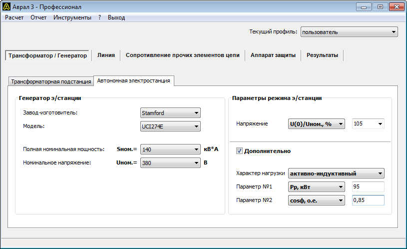
Point K-1 (G)
Calculation of the emergency short circuit mode and determination of the activation of the protection device at point K-1 when consumers are powered from diesel power plant(generator). All initial data and calculation results are presented in the program screenshots, see Fig. 2-6.


Point K-2 (G)
Calculation of the emergency short circuit mode and determination of the activation of the protection device at point K-2 when consumers are supplied from a diesel power plant (generator). All initial data and calculation results are presented in the program screenshots, see Fig. 7-10. Since entering the DES parameters is similar to calculating the K-1 (G) point, this screenshot is not shown here.


Point K-1 (T)
Calculation of the emergency short circuit mode and determination of the operation of the protection device at point K-1 when consumers are supplied from a centralized network (transformer). All initial data and calculation results are presented in the program screenshots, see Fig. 10-15.


Point K-2 (T)
Calculation of the emergency short circuit mode and determination of the operation of the protection device at point K-2 when consumers are supplied from a centralized network (transformer). All initial data and calculation results are presented in the program screenshots, see Fig. 16-19. Since entering the transformer parameters is similar to calculating the K-1 (T) point, this screenshot is not shown here.


Calculation results
According to the calculation results, the protection devices operate within the standard time when a short circuit occurs at points K-1 and K-2. At the same time, the operation of protection devices in emergency mode was tested when consumers were powered both from a diesel power plant and from a centralized network.
Designation of quantities
The report, database and calculation results of the program use symbols physical quantities. Below is full list their designations.
Transformer
- Uinn.nom., kV – Rated voltage high voltage windings;
- Unnn.nom, V – rated voltage of the low voltage winding;
- Snom, kV*A – rated apparent power;
- Unn, V – operating mode voltage of the LV winding;
- Ik.in., kA – short circuit current at the terminals of the HV winding;
- Sk, MV*A – short circuit power at the terminals of the HV winding;
- Xс, mOhm – equivalent inductive reactance of the system;
- R1, mOhm – positive sequence active resistance;
- R0, mOhm – zero-sequence active resistance;
- X1, mOhm – positive sequence inductive reactance;
- X0 – zero sequence inductive reactance.
Generator
- Snom., kV*A – rated apparent power;
- Unom., V – rated voltage;
- f, Hz – nominal frequency;
- U(0), V – generator voltage at the time preceding the short circuit;
- Рр, kW – estimated active load power of consumers;
- Qр, kvar – calculated reactive power of consumers’ load;
- Sp, kV*A – estimated total load power of consumers;
- Iр, А – calculated load current of consumers;
- cosф, p.u. - coefficient active power consumer loads;
- tgf, p.u. – reactive power factor of consumer load;
- f, deg. – angle between active and full power consumer loads;
- Xd”, p.u. – supertransient inductive reactance along the longitudinal axis;
- Xd’, p.u. – transient inductive reactance along the longitudinal axis;
- Xd, p.u. – synchronous inductive reactance along the longitudinal axis;
- Xq”, p.u. – supertransient inductive reactance along the transverse axis;
- Xq, p.u. – synchronous inductive reactance along the transverse axis;
- X2, p.u. – negative sequence inductive reactance;
- X0, p.u. – zero sequence inductive reactance;
- R, Ohm – active resistance of the armature winding;
- Td”, s – supertransient time constant along the longitudinal axis with the armature winding short-circuited;
- Td’, s – transition time constant along the longitudinal axis with the armature winding short-circuited;
- Ta, s – decay time constant of the aperiodic component of the armature current during a three-phase short circuit at the machine terminals;
- Ks or OKZ – short circuit ratio.
Line
- Npar., pcs. – number of parallel connected conductors;
- Fphase, sq.mm. – cross-section of the phase conductor;
- Fzero, sq.mm. – cross-section of the neutral conductor;
- t start, °C – initial temperature of the conductor;
- t pr., °C – design temperature of the conductor;
- R1 linear, mOhm/m – linear positive sequence active resistance;
- R0 linear, mOhm/m – linear zero-sequence active resistance;
- X1 linear, mOhm/m – direct sequence inductive reactance per unit;
- X0 linear, mOhm/m – linear zero-sequence inductive reactance;
- R1, mOhm/m – positive sequence active resistance of the line;
- R0, mOhm/m – active resistance of the line zero sequence;
- X1, mOhm/m – positive sequence inductive reactance of the line;
- X0, mOhm/m – inductive reactance of the zero sequence of the line;
- Dav. geom., m – geometric mean distance between phase wires (only for overhead lines).
Initial conductor temperature
- Inorm.calc., A – value of the line operating current in normal mode. In the case of several parallel connected conductors, the calculated current of the entire line is indicated, and not of an individual conductor;
- t ambient normal, °C – normalized temperature value environment. As a rule, when laying a line in the ground, the value is 15 °C, in the air - 25 °C;
- t ambient, °C – ambient temperature value;
- Iadditional cont., A – reference value for a long time permissible current(permissible continuous current) of the conductor. In the case of several parallel connected conductors, the current of an individual conductor is indicated, and not the entire line;
- t additional cont., °C – reference value permissible temperature continuous (normal) mode conductor.
- t start, °C – calculated value of the initial temperature of the conductor.
Other circuit elements
- Rpr, mOhm – total active resistance of other circuit elements;
- Xpr, mOhm – total inductive reactance of other circuit elements;
- Rk.s., mOhm – active resistance of contacts and contact connections;
- Rd, mOhm – active resistance of the electric arc;
- Rр, mOhm – active resistance of the reactor;
- Xр, mOhm – inductive reactance of the reactor;
- Rav, mOhm – active resistance of the circuit breaker coil;
- Xav, mOhm – inductive reactance of the circuit breaker coil;
- Rtt, mOhm – active resistance of current transformers;
- Xtt, mOhm – inductive reactance of current transformers.
Protection apparatus
- Inom, A – rated current;
- Irast., A – rated tripping current of the release (only for the circuit breaker) according to the passport;
- Tav.,s – response time;
- Кз – safety factor;
- Iav., A – operation current taking into account the safety factor.
Calculation results
- Ip(0), A – initial (time point T=0 after the occurrence of a short circuit) effective value periodic component of the short-circuit current.
- Ip(Tav), A – effective value of the periodic component of the short-circuit current after a period of time Tav (see below) after the occurrence of the short-circuit;
- ia(0), A – the largest initial value of the aperiodic component of the short-circuit current.
- ia(Tav), A – the value of the aperiodic component of the short-circuit current after a period of time Tav after the occurrence of the fault.
- iу, A – shock current.
- Iter.ek., A – effective value of the thermally equivalent current (see GOST 30323-95, clause 3.1.1).
- Tav., s – response time of the protection device. The value is copied into the table from the corresponding field in the Protection device group.
- Iav., A – tripping current of the protection device. The value is copied into the table from the corresponding field in the Protection device group.
 (1 ratings, on average: 5,00 out of 5)

