Rated voltage uk. Rated voltages of the electrical network
Rated voltages electrical networks general purpose alternating current in the Russian Federation are established by the current standard (Table 4.1). Table 4.1
The International Electrotechnical Commission (IEC) recommends standard voltages above 1000 V for systems with a frequency of 50 Hz, indicated in table. 4.2. Table 4.2 
There are a number of attempts to determine the economic zones of application of power transmission of different voltages. Satisfactory results for the entire scale of rated voltages in the range from 35 to 1150 kV are given by the empirical formula proposed by G. A. Illarionov: 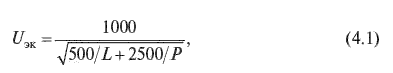
where L is the line length, km, P is the transmitted power, MW. In Russia, two voltage systems of AC electrical networks (110 kV and higher) have become widespread: 110-330-750 kV - in the UPS of the North-West and partly of the Center - and 110-220-500 kV - in the UPS of the central and eastern regions of the country ( see also section 1.2). For these UES, the voltage of 1150 kV, introduced in GOST in 1977, was taken as the next step. A number of constructed 1150 kV power transmission sections temporarily operate at a voltage of 500 kV. At the current stage of development of the UES of Russia, the role of backbone networks is performed by 330, 500, 750 networks, in a number of power systems - 220 kV. The first stage of distribution networks common use are networks of 220, 330 and partially 500 kV, the second stage - 110 and 220 kV; then the electricity is distributed through the power supply network of individual consumers (see paragraphs 4.5–4.9). The conditionality of dividing networks into backbone and distribution networks according to the rated voltage is that as the density of loads, the power of power plants and the coverage of the territory by electric networks increases, the voltage of the distribution network increases. This means that networks that perform the functions of backbone, with the advent of higher voltage networks in power systems, gradually “transfer” these functions to them, turning into distribution networks. A general-purpose distribution network is always built on a stepwise basis by sequentially “overlaying” networks of several voltages. The appearance of the next voltage step is associated with an increase in the power of power plants and the expediency of its issuance at a higher voltage. The transformation of the network into a distribution network leads to a reduction in the length of individual lines due to the connection of new substations to the network, as well as to a change in the values and directions of power flows along the lines. With the existing electrical load densities and a developed network of 500 kV, abandoning the classical scale of rated voltages with a step of about two (500/220/110 kV) and a gradual transition to a scale step of about four (500/110 kV) is a technically economically justified solution. This trend is confirmed by the experience of technologically advanced foreign countries when the intermediate voltage networks (220–275 kV) are limited in their development. Such a technical policy is carried out most consistently in the power systems of Great Britain, Italy, Germany and other countries. So, in the UK, 400/132 kV transformation is increasingly used (the 275 kV network is being mothballed), in Germany - 380/110 kV (the 220 kV network is being limited in development), in Italy - 380/132 kV (the 150 kV network is being mothballed), etc. d. The most widespread as distribution networks are 110 kV networks both in the UES with a voltage system of 220–500 kV and 330–750 kV. The share of 110 kV lines is about 70% of the total length of 110 kV overhead lines and above. This voltage is used to supply power to industrial enterprises and power centers, cities, electrification of railway and pipeline transport; they are the top level of electricity distribution in countryside. The voltage of 150 kV was developed only in the Kola energy system and is not recommended for use in other regions of the country. Voltages 6-10–20-35 kV are intended for distribution networks in cities, rural areas and industrial enterprises. The predominant distribution has a voltage of 10 kV; 6 kV networks retain significant specific gravity in length, but, as a rule, do not develop and, if possible, are replaced by 10 kV networks. This class is adjacent to the voltage of 20 kV available in GOST, which has received limited distribution (in one of the central districts of Moscow). The voltage of 35 kV is used to create 10 kV central networks in rural areas (35/0.4 kV transformation is less commonly used).
When designing the development of an electrical network, simultaneously with the development of the issue of the configuration of the electrical network, the issue of choosing its nominal voltage is being decided. The scale of nominal line voltages of electrical networks is established by GOST 721-77 and is next row:
0.38; 3; 6; 10; 20; 35; 110; 150; 220; 330; 500; 750; 1150 kV.
When choosing the rated mains voltage, the following are taken into account: general recommendations:
voltages of 6...10 kV are used for industrial, urban and agricultural distribution networks; the most common voltage for such networks is 10 kV; the use of 6 kV voltage for new facilities is not recommended, but can be used in the reconstruction of the existing electrical network if it has high-voltage motors for such a voltage;
currently, due to the growth of loads in the domestic sector, there is a tendency to increase the voltage of distribution networks in major cities up to 20 kV;
35 kV voltage is widely used to create power centers for 10 kV agricultural distribution networks; in connection with the growth of the capacities of rural consumers, a voltage of 110 kV is being used for these purposes;
voltages of 110 ... 220 kV are used to create regional distribution networks for general use and for external power supply of large consumers;
voltages of 330 kV and above are used to form the backbone links of the UES and to supply power to large power plants.
Historically, in our country, two voltage systems of electrical networks (110 kV and higher) have been formed. One system 110 (150), 330, 750 kV is typical mainly for the North-West and partly in the Center and North Caucasus. Another system 110, 220, 500 kV is typical for most of the country. Here, the voltage of 1150 kV is taken as the next step. Power transmission of this voltage was built in the 80s of the last century and was intended for the transmission of electricity from Siberia and Kazakhstan to the Urals. Currently, 1150 kV power transmission sections temporarily operate at a voltage of 500 kV. The transfer of this power transmission to a voltage of 1150 kV will be carried out later.
The rated voltage of an individual transmission line is mainly a function of two parameters: power R transmitted over the line, and the distance L to which this power is transferred. In this regard, there are several empirical formulas for choosing the nominal line voltage, proposed by different authors.
Still's formula
U nom = , kV,
Where R, kW, L, km, gives acceptable results at values L 250 km and R 60 MW.
Illarionov formula
U nom =  ,
,
Where R, MW; L, km, gives satisfactory results for the entire scale of rated voltages from 35 to 1150 kV.
The choice of the nominal voltage of an electrical network consisting of a certain number of lines and substations is, in general, the task of a technical and economic comparison various options. Here, as a rule, it is necessary to take into account the costs not only for power lines, but also for substations. Let's explain this with a simple example.
An electrical network is designed, consisting of two sections with a length L1 And L 2 (Fig. 4.1, A). A preliminary assessment of the rated voltage showed that a voltage of 220 kV should be taken for the head section, and 110 kV for the second section. In this case, you need to compare the two options.
In the first option (Fig. 4.1, b) the entire network is carried out for a voltage of 220 kV. In the second option (Fig. 4.1, V) the main section of the network is carried out at a voltage of 220 kV, and the second section - at a voltage of 110 kV.
In the second version, the line W 2 voltage 110 kV and substation 110/10 kV with transformer T will be cheaper than the line W 2 voltage 220 kV and substation 220/10 kV with transformer T 2 first option. However, a 220/110/10 kV substation with an autotransformer AT the second option will be more expensive than a 220/10 kV substation with a transformer T 1 of the first option.

a B C)
Rice. 4.1. Scheme ( A) and two options ( b) And ( V) network voltage
The final choice of mains voltage will be determined by comparing these options in terms of costs. If the cost difference is less than 5%, the option with the higher rated voltage should be preferred.
Each electrical network is characterized by a rated voltage for which its equipment is calculated. Rated voltage provides normal work consumers (EP), should give the greatest economic effect and is determined by the transmitted active power and the length of the transmission line.
GOST 21128-75 introduced a scale of nominal phase-to-phase voltages of electrical networks and receivers up to 1000 V AC: 220.380, 660 V.
GOST 721-77 introduced a scale of nominal phase-to-phase voltages of AC electrical networks over 1000 V:
0,38, 3, 6, 10, 20, 35, 110, 150, 220, 330, 500, 750, 1150.
In table. 2.1. a classification of electrical networks is presented, which shows the division into networks of low (LV), medium (SN), higher (HV), ultra-high (SVN) and ultra-high (UHN) voltage.
The EA load does not remain constant, but changes depending on the change in the operating mode (for example, in accordance with the course of the technological process of production), therefore, the voltage at the network nodes constantly deviates from the nominal value, which reduces the quality of electricity and entails losses. Studies have shown that for most power consumers, the stable zone is limited by the values of voltage deviations
Studies have shown that for most power consumers, the stable zone is limited by the values of voltage deviations.
As a rule, the voltage at the beginning of the line is greater than the voltage at the end and differs by the amount of voltage loss
To approximate the consumer voltage U 2 to the rated voltage of the electrical network and provide high-quality energy, the rated voltages of the network voltage generators are set by GOST by 5% more than the nominal
![]()
Since the primary windings of step-up transformers must be directly connected to the terminals of the generators, their rated voltages
The primary windings of step-down transformers are consumers in relation to the networks from which they are powered, so the condition must be met
IN Lately industry produces step-down transformers with a voltage of 110-220 kV with a voltage primary winding 5% more than the rated mains voltage
![]()

The secondary windings of both step-down and step-up transformers are sources in relation to the network they feed. Rated voltages secondary windings have values of 5-10% more than the rated voltage of this network
This is done in order to compensate for the voltage drop in the supplied network. On fig. 2.1 shows the voltage diagram, which clearly illustrates the above.
2.2. Modes of neutrals of electrical networks
The zero point (neutral) of three-phase electrical networks can be tightly grounded (Fig. 2.2, a), grounded through high-resistance (Fig. 2.2, b) or isolated from the ground (Fig. 2.2, c).

The neutral mode in electrical networks up to 1000 V is determined by the safety of network maintenance, and in networks above 1000 V - uninterrupted power supply, efficiency and reliability of electrical installations. According to the Rules for the Installation of Electrical Installations (PUE), the operation of electrical installations with voltages up to 1000 V is allowed both with dead-earthed and with isolated neutral.
End of work -
This topic belongs to:
LECTURE 1. GENERAL CHARACTERISTICS OF TRANSMISSION AND DISTRIBUTION SYSTEMS OF ELECTRIC ENERGY. SIMULATION OF ELECTRIC SYSTEM ELEMENTS
Plan ... Basic concepts and definitions ...
If you need additional material on this topic, or you did not find what you were looking for, we recommend using the search in our database of works:
What will we do with the received material:
If this material turned out to be useful for you, you can save it to your page on social networks:
| tweet |
All topics in this section:
Characteristics of the electrical energy transmission system
The basis of the transmission system electrical energy from power stations, producing it, to large areas of power consumption or distribution nodes of EPS are developed networks
Characteristics of electrical energy distribution systems
The purpose of distribution networks is the delivery of electricity directly to consumers with a voltage of 6-10 kV, the distribution of electricity between substations 6-110 / 0.38-35 kV district
Power transmission and distribution system
Section 1.3 describes the characteristics of EE transmission and distribution systems. Consider the relationship of these systems on an example. As an example, consider a simplified fundamental
Neutral mode of networks up to 1000 V with solidly grounded neutral
The most common are four-wire networks of three-phase current with a voltage of 380/220, 220/127, 660/380 (Fig. 2.3) (the numerator corresponds to the linear voltage, and the denominator corresponds to the phase voltage
Low voltage networks with isolated neutral
These are three-wire networks, which have found application for supplying especially responsible consumers with a small branching of networks while providing phase isolation control in networks. This
High voltage networks with isolated neutral
Consumer enabled on line voltage, neutral and ground in symmetrical mode match up. The voltage that the insulation must withstand is the voltage between phase and earth
High voltage networks with compensated neutral
These networks are also classified as networks with a low earth fault current (Fig. 2.9).
High-voltage networks with dead-earthed neutral
Such networks include networks with a rated voltage of 110 kV and above and high current ground faults (&g
Questions for self-examination
1. What is the rated voltage? 2. What is the nominal voltage range of electrical networks? 3. What is the classification of electrical networks by voltage, area coverage, purpose
LECTURE 3. PRINCIPLES OF DESIGN OF POWER LINES
Plan 1. Appointment overhead lines power transmission. 2. Design of overhead lines. 3. VL supports. 4. Wires VL. 5. Thunderstorm
Overhead power lines
Overhead lines are called lines intended for the transmission and distribution of EE through wires located on outdoors and supported by supports and insulators. Air
Cable power lines
cable line(KL) - a line for the transmission of electricity, consisting of one or more parallel cables, made by any laying method (Fig. 3.12). Are cable
Questions for self-examination
1. How are power lines classified according to design? 2. What factors determine the choice of the type of transmission line? 3.What requirements must be satisfied
Active resistance
Causes heating of wires ( heat loss) and depends on the material of current-carrying conductors and their cross section. For lines with small cross-section wires made of non-ferrous metal
Power line with steel wires
The main advantage of steel wires is their high mechanical properties. In particular, the tensile strength of steel wires reaches 600-700 MPa (60-70 kg/mm2
Questions for self-examination
1. For what purposes are substitution schemes used? List the advantages and disadvantages of these schemes. 2. What is the physical entity active resistance power lines? 3. As in to
LECTURE 5
Plan 1. Appointment, conventions, winding connection diagrams and vector diagrams voltage transformers. 2.Two-winding transformers.
Double winding transformers
When calculating the modes of three-phase electrical networks with a uniform loading of phases, transformers in the design diagrams are represented by an equivalent circuit for one phase.
Types and purposes of devices
Reactive power compensating devices are considered: static capacitor banks, shunt reactors, static thyristor compensators (STK) and synchronous compressors.
 (1 ratings, on average: 5,00 out of 5)

