What is alternating current definition. Alternating electric current. receiving alternating current
An alternating current is a current whose strength and direction change periodically over time. In technology, alternating current is used, varying in a sinusoidal manner. Receipt alternating current based on the phenomenon of electromagnetic induction.
In Fig. 161 schematically shows the production of sinusoidal alternating current. On the left in the diagram A shown: the poles of the magnet (north N and south S), with circles the different positions of the conductor in the magnetic field; in this case, the plus sign (+) indicates that in this position the current flows from us beyond the drawing plane, and the dot (.) indicates that the current flows from the drawing plane towards us.
In the diagram fig. 161, b represents the change in the strength and direction of the current along the external circuit of a closed conductor during one complete rotation between the poles of the magnets. Time is plotted along the horizontal axis of the graph, and vertical axis- current values. As follows from the graph curve, which is a sine wave, in one full turn, depending on the angle at which the conductor intersects the magnetic lines of force, the current value changes from zero to maximum, and in sign - from plus to minus.
A machine used to produce alternating current is called an alternating current generator, the principle of operation of which can be understood from the following.
If you make a conductor in the form of a coil, place it between the poles (Fig. 161, V) and rotate in a clockwise direction, then e will be induced in it. e., directed when it rotates under the north pole away from us and when it rotates under the south pole - toward us. Since the sides of the coil alternately move under the north pole, then under the south and at the same time intersect the magnetic lines of force at different angles, then e.g. e., induced in the turn, will change in value and direction. By connecting the ends of the coil to two contact rings, isolated from each other and from the shaft, and placing fixed brushes connected to an external circuit on the rings, we will obtain the variable e. d.s, and alternating current will flow in the external circuit.
Alternating current is characterized by the following quantities: period, frequency, amplitude.
The period is understood as the period of time during which a complete cycle of current changes in value and direction occurs. Each subsequent current period is a repetition of the previous one. The period is indicated by the letter T(see Fig. 161, b) and is sometimes expressed not in time, but in degrees.
Frequency is the number of cycles of current changes over time (periods of 1 s). Frequency is the reciprocal of the period, denoted by the letter f, i.e. f = 1/T. The hertz (Hz) is taken as the unit of frequency measurement. In the USSR, the alternating current frequency is 50 Hz.
Amplitude is the largest of the instantaneous current values that it reaches during a period. As follows from Fig. 161, b, in one period, the alternating current reaches its amplitude value twice.
The laws of direct current apply to alternating current circuits only in cases where these circuits consist of active resistances due to the use of incandescent lamps and rheostats. However, in many cases the AC circuit, except active resistance, contains self-induction coils, electric motor windings, capacitors and other devices that introduce the so-called " reactance, affecting the current in the alternating current circuit, as a result of which Ohm's law in the form in which it is applied to a direct current circuit is not valid for an alternating current circuit.
In order to find the effective current in an unbranched alternating current circuit, you need to calculate the total resistance of the circuit, taking into account all the resistors included in it. In general, if there is an active circuit in the circuit R, inductive Xl and capacitance X s The total resistance of the alternating current circuit is determined by the formula
Then the effective value of the current in the value of alternating current with resistors connected in series R ,X L And X s at known voltage U will be determined by the formula
I = U/Z.
This formula has the same meaning as Ohm's law for a direct current circuit. If you connect an ammeter to the AC circuit, it will show the value; 1.4 times less amplitude current. This current value is called the effective, or effective, value of the alternating current. For sinusoidal alternating current effective values voltage U And electromotive force E will also be 1.4 times less than their amplitude values. Measuring instruments, included in the alternating current circuit, show the effective values of the measured quantities.
In some cases, it is required to know not the effective, but the average value of the alternating current, which, as experiments and calculations show, is equal to its amplitude value multiplied by 0.637.
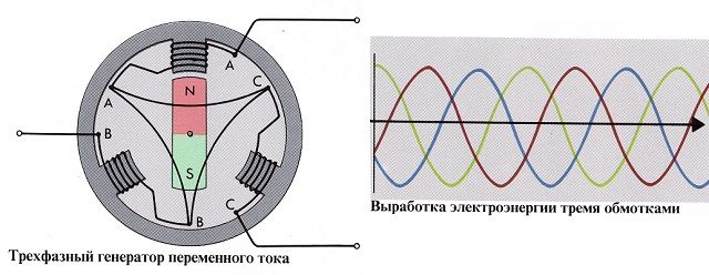
If a cylinder is rotated between the poles, on which there are not one, but three windings, each shifted relative to the others by an angle of 120 e, then the e.g. induced in each winding. d.s. reaches the amplitude value not at the same time, but differs in phases by 1/3 of the period (120°), as shown in Fig. 162.
In Fig. 162 on the left schematically shows a magnet with poles and a cylinder rotating between them with windings 1, 2 And 3, shifted relative to each other by 120°, and on the right is a graph of sinusoids of changes in e. d.s. current in these windings. As follows from the graph, the sinusoids are shifted relative to each other by a certain angle φ (Fig. 162), called phase. When rotating, each winding (coil) is an independent source of single-phase alternating current.
Three-phase current is a combination of three alternating currents of the same frequency, shifted by 1/3 of the period (120"). Three phase current produce three phase generators alternating current, the windings of which are connected in a star or triangle (Fig. 163).
When connected by a star (Fig. 163, A) the initial ends of all phase windings go to the external circuit, the second ends of the windings are connected to each other. The consumer can be connected between any pair of linear wires or between any linear wire and a neutral wire. When connected by a triangle (Fig. 163, b) the end of the first phase winding is connected to the beginning of the second, the end of the second to the beginning of the third, the end of the third to the beginning of the first.
The voltage between the beginning and end of a phase is called phase voltage and is designated Uph The voltage between the ends of the phases or wires is called linear voltage and is designated Ul. Accordingly, the current strength is called phase If or linear I l -
When connecting the generator or receiver phases with a star line current equal to phase, and line voltage 1.73 times the phase voltage. When connected by a triangle, the line voltage is equal to the phase voltage, and the line current is 1.73 times greater than the phase current.
1. What bodies are called magnets and how do their magnetic properties manifest themselves?
2. How can you determine the direction of the magnetic field and its lines of force arising around a conductor with current?
3. What is called magnetic induction, magnetic flux and magnetic circuit?
4. What is the essence of the device and operation of an electromagnet?
5. How does the interaction between magnetic field and a conductor carrying current?
6. What do you understand by electromagnetic induction, self-induction and mutual induction?
7. What do you understand by alternating current and what is the principle of its production?
8. What quantities characterize a variable? sinusoidal current?
9. What current is called three-phase and what is the principle of its production?
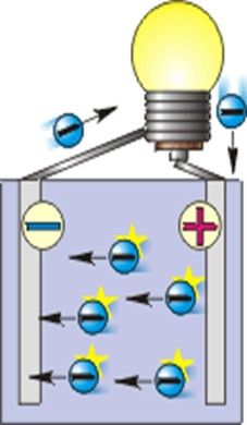
Movement of electrons in a conductor
To understand what current is and where it comes from, you need to have a little knowledge about the structure of atoms and the laws of their behavior. Atoms are made up of neutrons (neutral charge), protons (positive charge), and electrons (negative charge).
Electric current arises as a result of the directed movement of protons and electrons, as well as ions. How can we direct the movement of these particles? During any chemical operation, electrons are “torn off” and transferred from one atom to another.
Those atoms from which an electron has been “removed” become positively charged (anions), and those to which it has been attached become negatively charged and are called cations. As a result of these “running” of electrons, a electricity.
Naturally, this process cannot continue forever; the electric current will disappear when all the atoms of the system stabilize and have a neutral charge (excellent everyday example- an ordinary battery that “runs out” as a result of the end of a chemical reaction).
History of the study
The ancient Greeks were the first to notice an interesting phenomenon: if you rub an amber stone on woolen fabric, it begins to attract small items. The next steps were taken by Renaissance scientists and inventors, who built several interesting devices that demonstrated this phenomenon.
A new stage in the study of electricity was the work of the American Benjamin Franklin, in particular his experiments with the Leyden jar - the world's first electrical capacitor.
It was Franklin who introduced the concepts of positive and negative charges, and he also invented the lightning rod. And finally, the study of electric current became exact science after describing Coulomb's law.
Basic patterns and forces in electric current
Ohm's law - its formula describes the relationship between force, voltage and resistance. Discovered in the 19th century by the German scientist Georg Simon Ohm. The unit of electrical resistance is named after him. His discoveries were very useful directly for practical use.
The Joule-Lenz law says that in any area electrical circuit work is being done. As a result of this work, the conductor heats up. This thermal effect is often used in practice in engineering and technology ( great example– incandescent lamp).
The movement of charges results in work being done
This pattern got its name because 2 scientists, approximately simultaneously and independently, deduced it through experiments.
.
At the beginning of the 19th century, the British scientist Faraday realized that by changing the number of induction lines that penetrate a surface bounded by a closed loop, an induced current can be created. Extraneous forces acting on free particles are called electromotive force(induction emf).
Varieties, characteristics and units of measurement
Electric current can be either variables, or permanent.
A constant electric current is a current that does not change its direction and sign over time, but it can change its magnitude. Constant electric current most often uses galvanic cells as a source.
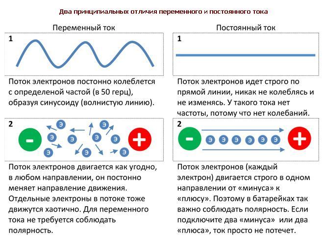
A variable is one that changes direction and sign according to the cosine law. Its characteristic is frequency. The SI units are Hertz (Hz).
In recent decades it has become very widespread. This is a type of alternating current that includes 3 circuits. In these circuits there are alternating emfs of the same frequency, but out of phase with one another by a third of the period. Each individual electrical circuit is called a phase.
Almost all modern generators produce three-phase electric current.
- Strength and amount of current
The strength of the current depends on the amount of charge flowing in the electrical circuit per unit time. Current strength is the ratio of the electric charge passing through the cross-section of a conductor to the time of its passage.
In the SI system, the unit of measurement for charge strength is the coulomb (C), and the unit for time is the second (s). As a result, we get C/s, this unit is called Ampere (A). The strength of the electric current is measured using a device - an ammeter.

- Voltage
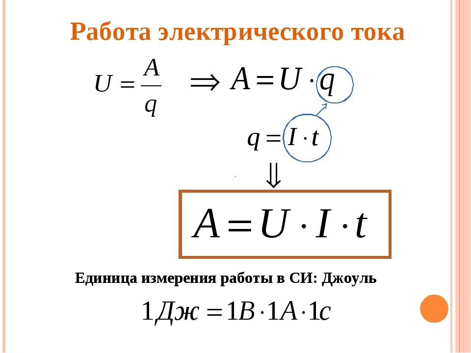
Voltage is the ratio of work to charge. Work is measured in joules (J), charge in coulombs. This unit is called Volt (V).
- Electrical resistance
The ammeter readings on the various conductors give different meanings. And in order to measure the power of the electrical circuit it would be necessary to use 3 devices. The phenomenon is explained by the fact that each conductor has a different conductivity. The unit of measurement is called Ohm and is denoted by the Latin letter R. Resistance also depends on the length of the conductor.
- Electrical capacity
Two conductors, which are isolated from one to the other, can accumulate electric charges. This phenomenon is characterized by physical quantity which is called electrical capacity. Its unit of measurement is farad (F).
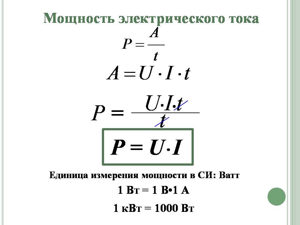
- Power and work of electric current
The work of electric current on a specific section of the circuit is equal to the multiplication of current voltage by force and time. Voltage is measured in volts, power in amperes, time in seconds. The unit of measurement for work was the joule (J).
Electric current power is the ratio of work to the time it is completed. Power is symbolized by the letter P and measured in watts (W). The power formula is very simple: Current multiplied by voltage.
There is also a unit called watt-hour. It should not be confused with watts, they are 2 different physical quantities. Watts measure power (the rate of consumption or transmission of energy), and watt-hours express the energy produced in a specific time. This measurement is often used for household electrical appliances.
For example, a lamp with a power of 100 W worked for one hour, then it consumed 100 Wh, and a lamp with a power of 40 watts will consume the same amount of electricity in 2.5 hours.
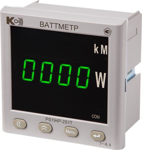
A wattmeter is used to measure the power of an electrical circuit.
Which type of current is more efficient and what is the difference between them?
Constant electric current is easy to use in case of parallel connection generators, for alternating it is necessary to synchronize the generator and the power system.
In history, an event called the “War of Currents” took place. This “war” took place between two brilliant inventors - Thomas Edison and Nikola Tesla. The first supported and actively promoted constant electric current, and the second alternating. The "war" ended with Tesla's victory in 2007, when New York finally switched to variable speed.
The difference in the efficiency of transmitting energy over a distance turned out to be huge in favor of alternating current. Constant electric current cannot be used if the station is located far from the consumer.
But the permanent one still found a field of application: it is widely used in electrical engineering, galvanization, and some types of welding. Also, constant electric current has become very widespread in the field of urban transport (trolleybuses, trams, metro).
Naturally, there are no bad or good currents, each type has its own advantages and disadvantages, the most important thing is to use them correctly.
Electricity- movement of charged particles along a conductor in a certain direction. More precisely, this is a value that shows how many charged particles passed through the conductor per unit of time. If in one second a number of charged particles the size of one coulomb passed through the cross-section of a conductor, then a current of one ampere (current designation in accordance with the international SI system) flows through this conductor. The amount of electric current (number of amperes) is called current strength. Depending on the change in value over time, current can be constant or variable.
D.C is an electric current that does not change its direction over time. Alternating current- over time, in a certain pattern, changes both its magnitude and direction. Moreover, these changes are repeated at certain intervals - that is, they are periodic.
Alternating and direct current in electrical installations
For three phase electrical network characteristic alternating current. The flow of alternating current through conductors is determined by the presence of a source of alternating electromotive force (EMF), which changes its value, both in magnitude and in direction. In this case, the change in the magnitude and direction of the EMF is carried out according to the sine law, that is, the graph of changes in alternating current over time is a sinusoid. The source of sinusoidal EMF is an alternating current generator.
Almost all electrical equipment of electrical installations and industrial enterprises It is powered by AC mains, as this is the most practical and has many advantages. But there is also some equipment that operates from a direct current network (or some of its parts): synchronous motor, electromagnetic, DC motor and others. In order to convert alternating current into D.C.(necessary to power the above electrical equipment) use rectifiers.
In addition, direct current is used to transmit high power through high-voltage lines electrical energy. In this case, when transmitting electrical energy over long distances, electrical losses are significantly less than with the same transmission using alternating current.
An alternating current is a current whose change in magnitude and direction is repeated periodically at equal intervals of time T.
In the field of production, transmission and distribution of electrical energy, alternating current has two main advantages over direct current:
1) the ability (using transformers) to simply and economically increase and decrease voltage, this is crucial for transmitting energy over long distances.
2) greater simplicity of electric motor devices, and therefore their lower cost.
The value of a variable quantity (current, voltage, emf) at any time t is called instantaneous value and is designated lowercase letters(current i, voltage u, emf – e).
The largest of the instantaneous values of periodically changing currents, voltages or emf is called maximum or amplitude values and are designated by capital letters with the index “m” (I m, U m).
The shortest period of time after which the instantaneous values of a variable quantity (current, voltage, emf) are repeated in the same sequence is called period T, and the totality of changes occurring during the period is cycle.
The reciprocal of the period is called frequency and is denoted by the letter f.
Those. frequency – the number of periods per 1 second.
Frequency unit 1/sec - called hertz (Hz). Larger units of frequency are kilohertz (kHz) and megahertz (MHz).
Obtaining alternating sinusoidal current.
In technology, alternating currents and voltages are sought to be obtained according to the simplest periodic law - sinusoidal. Because a sinusoid is the only periodic function that has a derivative similar to itself, as a result of which the shape of the voltage and current curves in all links of the electrical circuit is the same, which greatly simplifies the calculations.
To obtain industrial frequency currents, use alternators whose operation is based on the law of electromagnetic induction, according to which, when a closed circuit moves in a magnetic field, a current arises in it.
Circuit diagram of a simple alternator
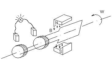
High-power alternating current generators, designed for voltages of 3–15 kV, are made with a stationary winding on the machine stator and a rotating electromagnet-rotor. With this design, it is easier to reliably insulate the wires of the fixed winding and it is easier to divert the current to the external circuit.
One revolution of the rotor of a two-pole generator corresponds to one period of alternating EMF induced on its winding.
If the rotor makes n revolutions per minute, then the frequency of the induced emf
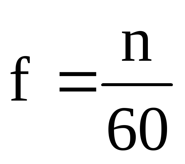 .
.
Because in this case the angular velocity of the generator 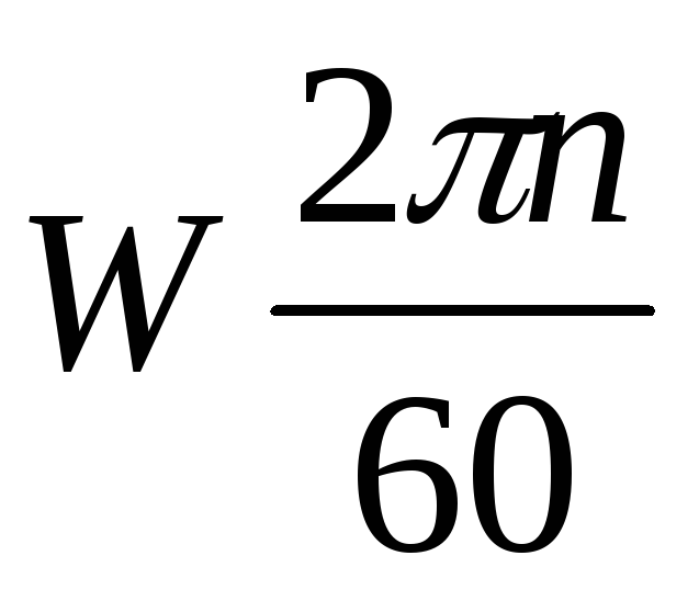 , then between it and the frequency induced by the EMF there is a relationship
 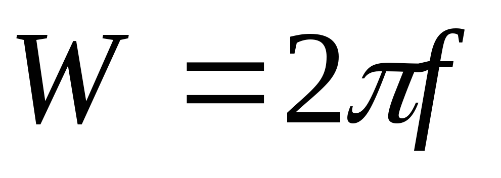 .
.
Phase. Phase shift.
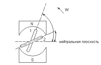
Let us assume that the generator has two identical turns at the armature, shifted in space. When the armature rotates, EMFs of the same frequency and with the same amplitudes are induced in the turns, because the coils rotate at the same speed in the same magnetic field. But due to the shift of turns in space, the EMF does not reach amplitude signs simultaneously.
If at the moment the time count begins (t=0) turn 1 is located at an angle relative to the neutral plane  , and turn 2 is at an angle
  . Then the EMF induced in the first turn:
and in the second:
At the time of countdown:
Electrical angles  And
And  the determining values of the emf at the initial moment of time are called initial phases.
The difference in the initial phases of two sinusoidal quantities of the same frequency is called phase angle .
![]()
The quantity for which zero values (after which it takes on positive values) or positive amplitude values is achieved earlier than the other is considered advanced in phase, and the one for which the same values are achieved later - lagging in phase.
If two sinusoidal quantities simultaneously reach their amplitude and zero values, then the quantities are said to be in phase
. If the phase shift angle of sinusoidal quantities is 180 0  , then they are said to change in antiphase.
>> Alternating electric current
§ 31 ALTERNATING ELECTRIC CURRENT
Free electromagnetic oscillations in the circuit quickly fade, and therefore they are practically not used. On the contrary, undamped forced oscillations are of great practical importance.
Alternating current in the lighting network of an apartment, used in factories and factories, etc., is nothing more than forced electromagnetic oscillations. Current and voltage change over time according to a harmonic law.
Voltage fluctuations are easy to detect using an oscilloscope. If voltage from the mains is applied to the vertical deflection plates of the oscilloscope, the time base on the screen will be a sinusoid (Fig. 4.8). Knowing the speed of the beam moving across the screen in the horizontal direction (it is determined by the frequency of the sawtooth voltage), we can calculate the oscillation frequency. The frequency of alternating current is the number of oscillations in 1 s.
The standard industrial AC frequency is 50 Hz. This means that over the course of 1 s, the current flows 50 times in one direction and 50 times in the opposite direction. A frequency of 50 Hz is accepted for industrial current in many countries around the world. In the USA the adopted frequency is 60 Hz.
If the voltage at the ends of the circuit changes according to a harmonic law, then the voltage electric field inside the conductors will also change harmoniously. These harmonic changes in field strength, in turn, cause harmonic oscillations in the speed of the ordered movement of charged particles and, consequently, harmonic oscillations in the current strength.
But when the voltage changes at the ends of the circuit electric field does not change instantly throughout the chain. Changes in the field propagate, although at a very high, but not at an infinitely high speed.
However, if the propagation time of field changes in the circuit is much less than the period of voltage oscillations, we can assume that the electric field in the entire circuit immediately changes when the voltage at the ends of the circuit changes. In this case, the current strength at a given time will have almost the same value in all sections of the unbranched circuit.
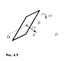
Alternating voltage in the sockets of the lighting network is created by generators at power plants. A wire frame rotating in a constant uniform magnetic field can be considered as the simplest model alternating current generator. The magnetic induction flux Ф, penetrating a wire frame of area S, is proportional to the cosine of the angle a between the normal to the frame and the magnetic induction vector (Fig. 4.9):
With uniform rotation of the frame, angle a increases in direct proportion to time:
where is the angular velocity of rotation of the frame. The magnetic induction flux changes according to the harmonic law:
Here the quantity plays the role of cyclic frequency.
According to the law of electromagnetic induction, the induced emf in the frame is equal to the rate of change of the magnetic induction flux taken with the “-” sign, i.e., the derivative of the magnetic induction flux with respect to time:
If an oscillatory circuit is connected to the frame, then the angular speed of rotation of the frame will determine the frequency of oscillations of the EMF values, voltage in different sections of the circuit and current strength.
We will further study forced electrical oscillations that occur in circuits under the influence of voltage changing with a cyclic frequency ω according to the law of sine or cosine:
u = U m sin t
or
u = U m cos t, (4.14)
where U m is the voltage amplitude, i.e. the maximum absolute value of the voltage.
If the voltage changes with a cyclic frequency, then the current in the circuit will change with the same frequency. But current fluctuations do not necessarily have to be in phase with voltage fluctuations. Therefore, in the general case, the current strength i at any time (instantaneous current value) is determined by the formula
Lesson content lesson notes supporting frame lesson presentation acceleration methods interactive technologies Practice tasks and exercises self-test workshops, trainings, cases, quests homework discussion questions rhetorical questions from students Illustrations audio, video clips and multimedia photographs, pictures, graphics, tables, diagrams, humor, anecdotes, jokes, comics, parables, sayings, crosswords, quotes Add-ons abstracts articles tricks for the curious cribs textbooks basic and additional dictionary of terms other Improving textbooks and lessonscorrecting errors in the textbook updating a fragment in a textbook, elements of innovation in the lesson, replacing outdated knowledge with new ones Only for teachers perfect lessons calendar plan for the year guidelines discussion programs Integrated Lessons (1 ratings, on average: 5,00 out of 5)

