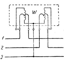
Scheme for connecting a wattmeter to a three-phase network. Active power measurement in three-phase current circuits
30.Methods for measuring active power in circuits alternating current
Measurement of active power in single-phase alternating current circuits is carried out with an electrodynamic or ferrodynamic wattmeter in the same way as measuring power in a circuit direct current: the current winding of the wattmeter is included in the cut of the phase wire, and the voltage winding is between phase and zero
Power measurement using the one-instrument method- this method is used to measure active power in symmetrical three-phase circuits.
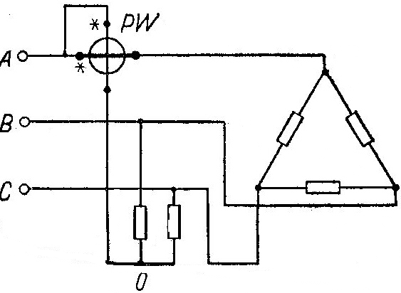 If the zero point is not available, then a wattmeter switching circuit with an artificial zero point is used. Isk..null..acc. created using two resistors, the resistance of each of which is equal to the resistance of the wattmeter voltage winding
Power measurement using the two-instrument method- used when measuring power in a three-phase three-wire circuit using two single-element wattmeters.
AND 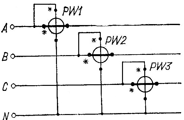 power measurement using the three-instrument method - used when measuring power in a three-phase four-wire circuit (three single-element wattmeters are used


31. Methods for measuring reactive power in alternating current circuits
To measure reactive power, devices of electrodynamic or ferrodynamic systems are used in which the angle of rotation of the moving part is proportional not to cos, but to sin; such devices are called wattmeters. However, to measure reactive power in three-phase circuits, ordinary wattmeters can be used if they are connected according to equivalent voltage circuits.
Rule for turning on a wattmeter to measure reactive power:
1. The current winding of the wattmeter is switched on in the same way as when the active power changes.
2. The voltage winding is switched on at a voltage that would lag by 90 from the voltage supplied to the winding when the active power changes.
AND 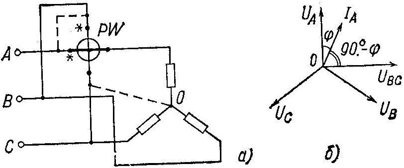 measurement of reactive power using one device method - used when connecting a conventional single-phase electrodynamic or ferodynamic wattmeter, designed to measure active power, into a three-phase three- or four-pass circuit.
Reactive power measurement using the two-instrument method - used in a three-phase three-wire circuit with both symmetry and asymmetry of currents.

AND 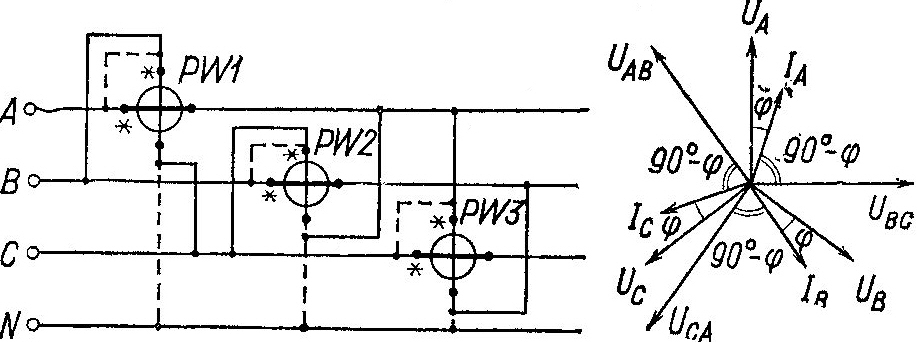 measurement of reactive power using the three-instrument method - used in three-phase four-wire circuits with both symmetry and asymmetry of currents.
.
Lissajous figure method. This method is used to measure the frequency of sinusoidal voltages. One of the inputs (for example, the input of channel Y) is supplied 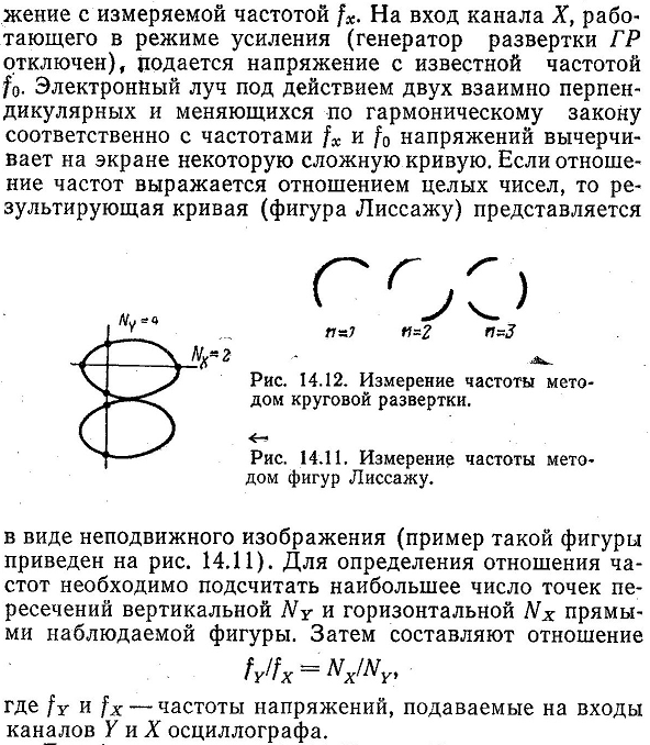
32. Electrical energy measurement. Single-phase induction meter. Switching schemes. Operating principle.
Measurement of active and reactive energy in single-phase and three-phase, three-wire and four-wire alternating current circuits can be carried out using special integrating electrical measuring instruments - single-phase and three-phase electric meters.
In those. lit. elect. Meters designed to account for energy in single-phase alternating current circuits are called single-phase meters.
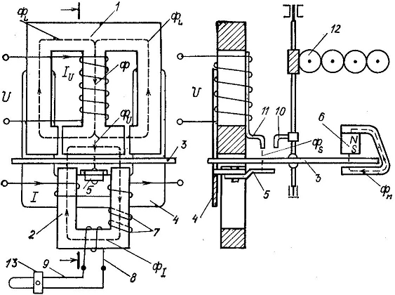
An induction measuring mechanism is used as the rotating element of a single-phase meter. The principle of operation of the mechanism is based on the interaction of two or more alternating magnetic fluxes with currents induced or in a movable aluminum disk.
33. Moments acting on the disk of a single-phase induction meter.
Torque M is equal to: 
Where F1 and F2 are the flows crossing the aluminum disk; f-frequency of measurement of flows F1 and F2; φ-angle of phase shift between flows Ф1 and Ф2.
To create a torque, at least two components of one flow are required, having a phase shift and displaced in space.
The torque reaches its value when the phase shift between the flows Ф1 and Ф2 is equal to 90 (sinψ=1)
The torque depends on the frequency of measuring the flows F1 and F2.
The friction moment is a variable value depending on the angular speed of rotation of the disk. The compensation moment at a changed voltage value is a constant value, therefore the equality of the compensation moment and the friction moment occurs only at one very specific load. During the operation of the meter, there are cases when the compensation torque exceeds the friction moment, as a rule, at low load, and as a result, the meter disk begins to rotate under the influence of the compensation torque even if I → 0, that is, when the consumer does not consume energy, this phenomenon is called self-propelled counter.
Rotation of the counter disk under the influence of voltage applied to the terminals of the parallel circuit and in the absence of current in the series circuit. self-propelled To eliminate self-propelling, a hook made of ferromagnetic material is attached to the disk axis. Flag position 11 is magnetized by magnetic currents creating a compensating moment and attracts the hook, thereby eliminating self-propelled
34. Measurement of phase shift. Electromechanical phase meters. Oscillographic methods for measuring phase shift.
Electromechanical phase meters, Electrodynamic and ferrodynamic ratiometers can be used to construct phase meters (both indicating and recording) designed to measure the phase shift between voltage and current in the load and power factor.
Based on electrodynamic mechanisms, it is possible to construct phase meters for measuring cosφ in three-phase alternating current circuits. According to the principle of operation, it is similar to a single-phase phase meter, but the necessary phase shifts between currents in the windings of the frames of the moving part of the device can be obtained more simply using 120-degree shifts between voltages and currents three-phase circuit. Such a device gives correct readings in a three-phase circuit with symmetrical voltages and currents. In the case of an asymmetrical three-phase circuit, we can only talk about the phase difference between the current and voltage in each phase.
Oscillographic methods for measuring phase. The linear sweep method involves the use of a dual-beam oscilloscope or a single-beam oscilloscope with an electronic switch. In this case, an image of two voltages is created on the oscilloscope screen, a phase shift  between which you need to measure. If voltages U1 and U2
When the Y input of the oscilloscope is supplied through an electronic switch, the images are created by dashed lines.
between which you need to measure. If voltages U1 and U2
When the Y input of the oscilloscope is supplied through an electronic switch, the images are created by dashed lines.
The ellipse method is used to measure the phase shift between sinusoidal voltages. Voltages U1 and U2 are supplied to the inputs of channels U and X (channel X works in signal amplification mode And 2 ). The image of an ellipse is obtained on the oscilloscope screen
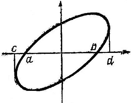
The ellipse method allows you to measure within 0-90° without determining the sign of the phase angle.
34. Frequency measurement. Electromechanical frequency meters. Oscillographic methods for measuring frequency.
Electromechanical frequency meters . These instruments are used to measure frequencies in the range of 20-2500 Hz mainly in energy circuits and are based on electromagnetic and electrodynamic (ferrodynamic) mechanisms.
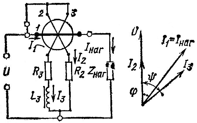
Electrical circuit of an electrodynamic frequency meter based on a ratiometric mechanism and vector diagram currents are shown in Fig.
Lissajous figure method. This method is used to measure the frequency of sinusoidal voltages. A voltage is supplied to one of the inputs (for example, to the input of channel Y).
Active power in a single-phase circuit is measured using single-element wattmeters. Extension of measurement ranges in alternating current circuits is carried out using current and voltage measuring transformers.
Power measurement using the one-device method. When using the single instrument method, power is measured using a single-element wattmeter. The method is used when measuring power in single-phase circuits and symmetrical three-phase circuits (the complex resistances of the phases are the same). In both cases, the voltage winding of the wattmeter is connected to the phase voltage, and the current winding is connected to the cut of the wire of any phase. In Fig. Figure 11.8 shows the connection of a single-element wattmeter to a single-phase alternating current circuit. Neglecting methodological error, let's record the wattmeter readings:
P PW = UI cos j,
Where U And I– effective values load voltage and current ; j =(U,I).
The wattmeter reading in this case will correspond to the power of one phase. To obtain the power of the entire three-phase circuit, it is necessary to triple the wattmeter reading, i.e. P = 3P PW.
Switching on the fixed coil of a wattmeter in series with the load is possible only at load currents of 10-20 A. At high load currents, the fixed coil of the wattmeter is connected through a current transformer ( TA). When measuring in high voltage circuits (over 600 IN) the moving coil of the wattmeter is not connected directly to the measuring circuit, but through a voltage transformer ( TV), and the stationary coil of the wattmeter - through TA(regardless of the load current value).
The value of the measured power is determined by the wattmeter reading multiplied by the product of the transformation ratios TV And TA:
R x = R R W K U nom K I nom,
Where R x – measured value of active power in the load circuit; R R W– wattmeter reading; KU nom, K I nom – nominal transformation ratios, respectively, TV And TA.
The measured power value will differ from the actual value
errors in transmitting voltage and current values, as well as angular errors transformers. Electrodynamic wattmeters are made multi-range, high classes accuracy (0.1; 0.2) with a range of measured powers from tenths W up to 3 – 6 kW. For rough measurements, ferrodynamic wattmeters are used as panel devices.
It should be noted that active power measurement with single-element wattmeters is carried out only in laboratory practice. For technical measurements in industrial conditions, two-element wattmeters are used to measure active power in three-phase three-wire circuits, and three-element wattmeters in four-wire circuits.
In addition to electrodynamic wattmeters, electronic rectifier, thermoelectric, digital and other wattmeters are used to measure power.
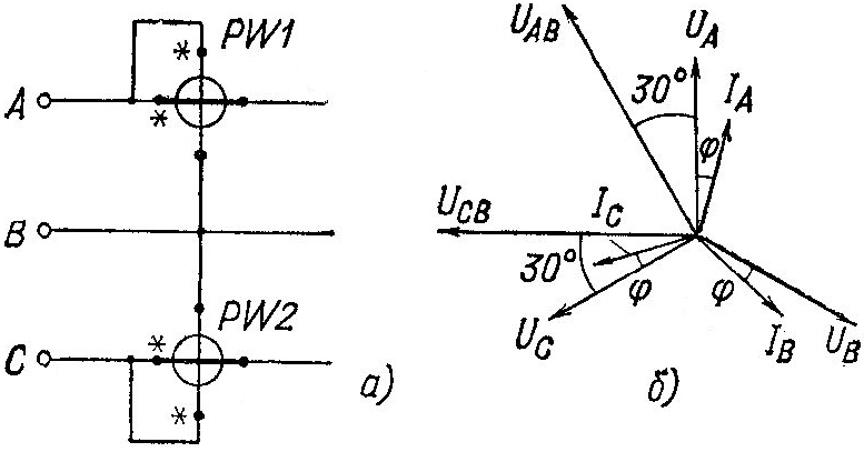
Power measurement using the two-instrument method. The two-instrument method is used to measure power in a three-phase, three-wire network using two single-element wattmeters. The method gives correct results regardless of the connection diagram and the nature of the load, both with symmetry and asymmetry of currents and voltages. In addition, the two-instrument method is used to include the elements of a two-element wattmeter when measuring its power in a three-phase three-wire network
In Fig. Figure 11.9 shows a circuit diagram for connecting two single-element wattmeters. Typically the current winding of one wattmeter, for example, PW1, comes into phase A, and the current winding of another wattmeter is PW2 – in phase WITH. The voltage windings of the wattmeters are switched on line voltages as shown in Fig. 11.9. When measuring power using the two-instrument method general power circuit is equal to the algebraic sum of the wattmeter readings
P = P W 1 + P W 2 ,
Where P W 1 =U A B I A cos j 1; P W 2 =U C B I C cos j 2, (j 1 - phase shift between vectors U A B And I A ; j2 – phase shift between vectors U C V And I C). Or
P W 1 = U L I L cos(30 o -j);
P W 2 = U L I L cos(30 o +j),
Where j- phase shift between voltage and current in a phase.
The power of any 3-phase system is calculated by the formula:
![]()
Thus, the sum of the wattmeter readings PW1 And PW2 is nothing more than the power of a three-phase circuit.
Power measurement using the three-instrument method. The three-instrument method is used when measuring power in a three-phase, four-wire circuit (using three single-element wattmeters connected to each phase). Just like the two-device method, the three-device method gives correct results regardless of the connection diagram and the nature of the load, both with symmetry and asymmetry of currents and voltages. According to the circuit that implements the method of three devices, elements of three-element three-phase wattmeters are also included. Obviously, to find the power of a 3-phase four-wire circuit, it is necessary to take the algebraic sum of all wattmeters.
The wattmeter consists of two coils: a fixed one, consisting of large number turns of thick wire, and movable 2, consisting of a large number of turns of thin wire. When the wattmeter is turned on, the load current passes through a fixed coil connected in series to the circuit, and the moving coil is connected in parallel to the consumer. To reduce power consumption in the parallel winding and reduce the weight of the moving coil, additional resistance 3 made of manganin is connected in series with it. As a result of the interaction of the magnetic fields of the moving and stationary coils, a torque arises that is proportional to the currents of both coils:

that is, the torque of the device is proportional to the power consumed in the circuit.
In order for the instrument needle to deviate from zero to the right, it is necessary to pass current through the coil in a certain direction.
To do this, the two terminals indicating the beginning of the windings are marked with a * and are electrically connected. The wattmeter scale indicates rated current And Rated voltage device. So, for example, if the scale of the device indicates 5 A and 150 V, then the device can measure power up to 750 W. The scales of some wattmeters are graduated in divisions. If, for example, a 5 A and 150 V wattmeter has 150 divisions, then the division value, or wattmeter constant, is 750: 150 = 5 W/div.
In addition to electrodynamic wattmeters, ferrodynamic system wattmeters are also used to measure power in DC circuits.
2. Single phase alternating current. When connecting an electrodynamic wattmeter to an alternating current circuit magnetic fields moving and fixed coils, interacting with each other, will cause rotation of the moving coil. The instantaneous torque of the moving part of the device is proportional to the product of the instantaneous current values in both coils of the device. But due to rapid changes in currents, the moving system will not be able to follow these changes and the rotational torque of the device will be proportional to the average or active power. Therefore, by the angle of rotation of the moving part of the wattmeter, one can judge the amount of active power consumed by the circuit.
|
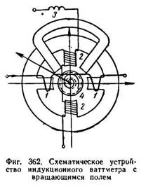
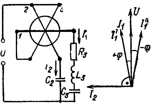
To measure alternating current power, induction system wattmeters are also used. In fig. Figure 362 shows a circuit diagram for connecting an induction wattmeter with a rotating magnetic field. A 1-1 series wire, consisting of a small number of turns of thick wire, is located on two opposite pole protrusions and is connected in series to the circuit. A parallel winding of 2-2 wattmeters, consisting of a large number of turns of thin wire, is located on two separate pole projections. Inductive reactance 3 is connected in series with winding 2-2, serving for semi-
The 90° shift angle between its voltage and current is measured. Thus, with a purely active load, we obtain a shift of 90° between the currents in the series and parallel windings, which is a necessary condition creating a rotating magnetic field. When the device is turned on, this field, crossing the aluminum cylinder 4, induces eddy currents in it, which, interacting with the field, create a torque acting on the moving part of the device. Its rotation angle at any load will be proportional to the active power consumed by the circuit:
![]()
A schematic diagram of an induction wattmeter with a traveling field was given in Fig. 335.
When measuring power with a wattmeter in low voltage networks with high currents current transformers are used. To reduce the potential difference between the wattmeter windings, the primary and secondary circuits of the current transformer have common point. Secondary winding The transformer is not grounded, since this would mean grounding one wire of the network.
To determine the power of the network P 1 in this case, you need to multiply the reading of the wattmeter P 2 by the transformation ratio of the current transformer:
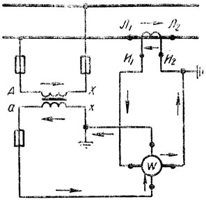
In high-voltage networks, when measuring power, voltage and current measuring transformers are used (Fig. 363).
So, for example, if a voltage transformer of 6000/100 V and a current transformer of 150/5 A are installed to the wattmeter, and the wattmeter shows 80 W, then the network power will be:
|
When turning on wattmeters (meters) through the measuring
Transformers must be connected to these devices so that currents pass through their windings in the same direction as if they were directly connected to the network.
In addition to the wattmeter, the power of single-phase alternating current can be determined from the readings of three instruments: an ammeter, a voltmeter and a phase meter according to the formula:
![]()
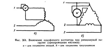
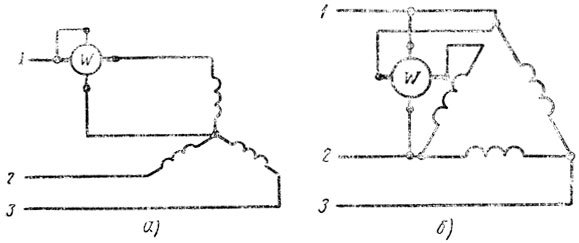
3. Three-phase alternating current. With uniform load three phase system To measure power, use one single-phase wattmeter, connected according to the circuit shown in Fig. 364 (a - for a star connection; b - for a triangle connection). In this case, flows through the series winding of the wattmeter phase current, and the parallel winding is connected to the phase voltage. Therefore, the wattmeter will show the power of one phase. To obtain the power of a three-phase system, you need to multiply the reading of a single-phase wattmeter by three.
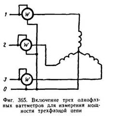
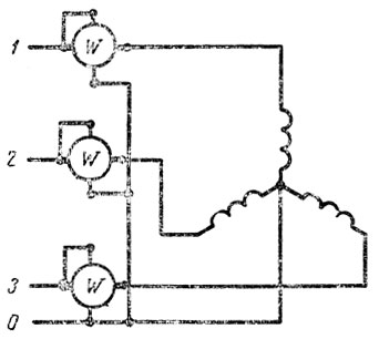
With uneven load in a four-wire network three-phase current to measure power, a circuit of three wattmeters is used (Fig. 365). Each single-phase wattmeter measures the power of one phase. To obtain the power of a three-phase system, it is necessary to take the sum of the readings of three wattmeters.
With a variable load, it is difficult to obtain simultaneous readings from three wattmeters. In addition, three single-phase wattmeters take up a lot of space. Therefore, one three-element three-phase wattmeter is often used, which is a combination of three single-phase wattmeters in one device.
|
|
A three-element electrodynamic wattmeter has three movable parallel coils mounted on one axis connected to the arrow, and the total torque obtained as a result of the addition of the mechanical forces of each coil will be proportional to the power consumed in the three-phase network. In other designs, moving coils located in different places, are connected to each other by flexible tapes and transmit the total force to the axis with the arrow.
The active power of a three-phase network with a uniform load can be determined
Using three instruments: an ammeter, a voltmeter and a phase meter according to the formula:
The power of a three-wire, three-phase network under any load (uniform or uneven), regardless of the method of connecting the consumer (star or delta), can be measured using a two-wattmeter circuit.
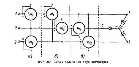
According to Kirchhoff’s first law, the sum of the instantaneous current values of all three phases is zero:
The resulting equation shows that one of the wattmeters must be turned on so that the first phase current flows through its current coil, and the voltage coil is under the difference in voltages of the first and second phases; another wattmeter should be turned on so that the third phase current flows through its current coil, and the voltage coil is under the voltage difference between the third and second phases.
By adding up the readings of both wattmeters, we get the power of all three phases.
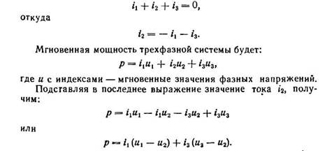
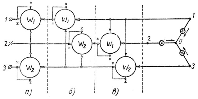
In fig. 366 shows three variants of the circuit of two wattmeters.
From the diagrams on fng. 366 it can be seen that the series windings of the wattmeters are connected to any two linear wires of the network. The beginnings of the parallel windings of each wattmeter are connected to the same wire into which the series winding of the wattmeter is connected. The ends of the parallel windings are connected to the third line wire.
With a uniform active load (=1), the wattmeter readings are equal to each other. If not equal to unity, the wattmeter readings will not be equal. If equal = 0.5, one of the wattmeters will show zero. At less than 0.5, the needle of this device will begin to deviate to the left. To get a reading from the device, you need to switch the ends of its series or parallel windings.
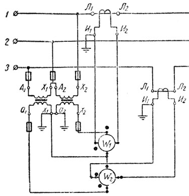
To measure the active power of a three-phase system using the readings of two wattmeters, you need to add their readings or subtract from the reading of one wattmeter the reading of another wattmeter, which was negative. The circuit for measuring power with two wattmeters using voltage and current measuring transformers is shown in Fig. 367.
It is more convenient to measure power using a three-phase wattmeter, which combines two devices connected according to the two-wattmeter circuit and acting on one common axis to which the arrow is connected.
|
In high voltage networks, a three-phase wattmeter is switched on using voltage and current measuring transformers.
D.C. From the DC power formula
It can be seen that power can be determined by multiplying the ammeter and voltmeter readings. However, in practice, power measurements are usually made using special devices- wattmeters. The wattmeter (Fig. 230) consists of two coils: fixed 1, consisting of a small number of turns of thick wire, and movable 2, consisting of a large number of turns of thin wire. When the wattmeter is turned on, the load current passes through a fixed coil connected in series to the circuit, and the moving coil is connected in parallel to the consumer. To reduce power consumption in the parallel winding and reduce the weight of the moving coil, additional resistance 3 made of manganin is connected in series with it. As a result of the interaction of the magnetic fields of the moving and stationary coils, a torque arises that is proportional to the currents of both coils:
M = c 1 I 1 I 2 .
The current of the parallel winding I 2 at a constant resistance of the parallel circuit is proportional to the circuit voltage. From here
M = c 2 I 1 U = c 2 P,
that is, the torque of the device is proportional to the power consumed in the circuit.
In order for the instrument needle to deviate from zero to the right, it is necessary to pass current through the coil in a certain direction.
To do this, the two terminals indicating the beginning of the windings are marked with a * and are electrically connected. The wattmeter scale indicates the rated current and rated voltage of the device. So, for example, if the scale of the device indicates 5 A and 150 V, then the device can measure power up to 750 watts. The scales of some wattmeters are graduated in divisions. If, for example, a 5 A and 150 V wattmeter has 150 divisions, then the division value, or the wattmeter constant, is 750:150 = 5 W/div. In addition to electrodynamic wattmeters, ferrodynamic system wattmeters are also used to measure power in DC circuits.
Single phase AC. When an electrodynamic wattmeter is connected to an alternating current circuit, the magnetic fields of the moving and fixed coils, interacting with each other, will cause the moving coil to rotate. The instantaneous value of the rotation moment of the moving part of the device is proportional to the product of the instantaneous current values in both coils of the device.
The rotational torque of the device is proportional to the average, or active, power P = U ⋅ I cos φ. By the angle of rotation of the moving part of the wattmeter, one can judge the amount of active power consumed by the circuit.
Ferrodynamic system wattmeters are also used to measure AC power.
When measuring power with a wattmeter in low-voltage networks with high currents, current transformers are used.
To determine the power of the network P 1 in this case, you need to multiply the reading of the wattmeter P 2 by the transformation ratio of the current transformer k T:
In high-voltage networks, voltage and current measuring transformers are used when measuring power (Fig. 231). To obtain the power of the network P 1, you need to multiply the reading of the wattmeter P 2 by the product of the transformation ratios of the voltage and current transformers:
P 1 = P 2 k n k T .
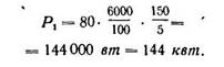
So, for example, if the wattmeter is connected through a voltage transformer of 6000/100 V and a current transformer of 150/5 A and the wattmeter shows 80 W, then the network power will be
P 1 = 80 ⋅ 6000 / 100 ⋅ 150 / 5 = 144000 W = 144 kW.
When connecting wattmeters (meters) through measuring transformers, these devices must be connected so that currents pass through their windings in the same direction as if they were directly connected to the network.
In addition to the wattmeter, the power of single-phase alternating current can be determined by the readings of three instruments: ammeter, voltmeter and phase meter - according to the formula
Three-phase alternating current. At symmetrical load In a three-phase system, to measure power, one single-phase wattmeter is used, connected according to the circuit shown in Fig. 232 (a - for a star connection; b - for a triangle connection). In this case, phase current flows through the series winding of the wattmeter, and the parallel winding is connected to phase voltage. Therefore, the wattmeter will show the power of one phase. To obtain the power of a three-phase system, you need to multiply the reading of a single-phase wattmeter by three.
With an asymmetrical load in a four-wire three-phase current network, a circuit of three wattmeters is used to measure power (Fig. 233). Each single-phase wattmeter measures the power of one phase. To obtain the power of a three-phase system, it is necessary to take the sum of the readings of three wattmeters.
With a variable load, it is difficult to obtain simultaneous readings from three wattmeters. In addition, three single-phase wattmeters take up a lot of space. Therefore, one three-element three-phase wattmeter is often used, which is a combination of three single-phase wattmeters in one device. A three-element electrodynamic wattmeter has three movable parallel coils mounted on one axis connected to the arrow, and the total torque obtained as a result of the addition of the mechanical forces of each coil will be proportional to the power consumed in the three-phase network. In other designs, moving coils located in different places are connected to each other by flexible tapes and transmit the total force to the arrow axis.
The active power of a three-phase network with a uniform load can be determined using three instruments: an ammeter, a voltmeter and a phase meter - according to the formula
P = √3 UI cos φ,
where U and I are linear voltages and current;
φ - shift angle between phase voltage and current.
The power of a three-wire three-phase network under any load (uniform or uneven), regardless of the method of connecting consumers (star or triangle), can be measured using a two-wattmeter circuit.
According to Kirchhoff's first law, the sum of the instantaneous current values of all three phases is zero:
i 1 + i 2 + i 3 = 0,
i 2 = - i 1 - i 3 .
Instantaneous power three-phase system will be
p = i 1 u 1 + i 2 u 2 + i 3 u 3 ,
where u with indices are instantaneous values of phase voltages.
Substituting the value of current i 2 into the last expression, we obtain
p = i 1 u 1 - i 1 u 2 - i 3 u 2 + i 3 u 3,
p = i 1 (u 1 - u 2) + i 3 (u 3 - u 2).
The resulting equation shows that one of the wattmeters must be turned on so that the first phase current flows through its current coil, and the voltage coil is under the difference in voltages of the first and second phases; another wattmeter should be turned on so that the third phase current flows through its current coil, and the voltage coil is under the voltage difference between the third and second phases.
By adding up the readings of both wattmeters, we get the power of all three phases.
In Fig. 234, a - c shows three options for a circuit of two wattmeters.
The diagrams show that the series windings of wattmeters are connected to any two linear wires of the network. The beginnings of the parallel windings of each wattmeter are connected to the same wire into which the series winding of the wattmeter is connected. The ends of the parallel windings are connected to the third line wire.
With a symmetrical active load and cos φ = 1, the wattmeter readings are equal. When cos φ is not equal to unity, the wattmeter readings will not be equal. At cos φ equal to 0.5, one of the wattmeters will show zero. When cos φ is less than 0.5, the needle of this device will begin to deviate to the left. To get a reading from the device, you need to switch the ends of its series or parallel windings.
To measure the active power of a three-phase system using the readings of two wattmeters, you need to add their readings or subtract from the reading of one wattmeter the reading of another wattmeter, which was negative. The circuit for measuring power with two wattmeters using voltage and current measuring transformers is shown in Fig. 235.
It is more convenient to measure power using a three-phase wattmeter, which combines two devices connected according to the two-wattmeter circuit and acting on one common axis to which the arrow is connected. In devices of electrodynamic and ferrodynamic systems, two moving coils located on the same axis or connected by flexible tapes rotate one axis. In induction system devices, two elements rotate two disks sitting on the same axis, or two elements act on one disk. The connection diagram for a two-element three-phase wattmeter is shown in Fig. 236.
In high voltage networks, a three-phase wattmeter is switched on using voltage and current measuring transformers.
 (1 ratings, on average: 5,00 out of 5)

