Three-phase star connection. Symmetrical load
Lab 8
THREE-PHASE CIRCUITS.
STAR LOAD CONNECTION
The purpose of the work: to study the three-phase current circuit when the receiver is connected by a star in symmetrical and asymmetric modes. Determine the role of the neutral (zero) wire.
BASIC CONCEPTS
A three-phase alternating current system is a set of three single-phase electrical circuits in which sinusoidal EMFs of the same frequency operate, shifted in phase by 1/3 of the period and created by a common source electrical energy. The three-phase system was invented and developed in every detail by the talented Russian engineer Dobrovolsky in 1891.
The source of energy in a three-phase system is a three-phase generator. In the grooves of its stator there are three electrically isolated from each other windings (phase windings or simply phases) of the generator. If the generator rotor is bipolar, then the axes of the phase windings of the generator are rotated in space relative to each other by an angle of 2p/3. When the rotor rotates, sinusoidal phase EMFs are induced in the phase windings of the stator. Due to the symmetry of the generator design, the maximum Em and effective E EMF values in all phases are the same.
The connection of the phases (windings) of the generator can be carried out according to the “star” or “triangle” scheme. The phases of a three-phase generator are usually denoted by the first letters of the Latin alphabet: A, B, C. The alternation of the phases of the generator is strictly defined and is determined by the change in time of the phase EMF, i.e., in the order of the EMF maxima: first phase A, then after 1/3T of phase B and through 2 / 3T of phase C. Such an alternation sequence is called direct.
Instantaneous EMF values three-phase windings generator are:
eA=Emsinwt eB=Emsin(wt-2/3p) eC=Emsin(wt-4/3p) (1)
Figure 8.1 shows graphs of instantaneous values of phase EMF and three vectors corresponding to them effective values EMF.
As can be seen from Fig. 8.1, the sum of the instantaneous values of the EMF at any time is zero, therefore, the geometric sum of the effective values of the phase EMF of the generator is also equal to zero:
EA+EB+EU=0
According to Fig. 8.1, we express the complex values of the EMF of a three-phase generator through the same effective value for all three phases E, then
EA=E∙ej0
EB=E e-j2/3p (3)
EU=E e2/3p
To obtain a three-phase system, it is also necessary to connect the receiver phases in a certain way, usually in a star or delta configuration.
B at present three-phase system is the basis for the transmission and distribution of energy.
The phase windings of a three-phase generator can be connected to three receivers in a star configuration. A “star” is such a connection in which the ends of the phases are connected to one common point N called neutral or zero, and linear wires are connected to the beginnings of phases A, B, C. The load phases with the zero point n and the beginnings of the phases a, b, c are also connected to the "star" (Fig. 8.2).
Wire connecting points N-n, is called neutral or zero. Wires connecting points A-a, B-in and C-s, are called linear.
Taking the resistance of all wires to zero, you can determine the currents of the three phases of the receiver and generator:
I A= E A/ZA ; I B= E B/ZB ; I C= E C/ZC. (4)
Currents I A, I b, I C flowing through linear wires are called
linear (IL). The currents flowing in the generator phases and in the load phases are called phase currents (If). For star connection line currents equal to phase, that is
IL=I f (5)
According to Kirchhoff's first law, the current in the neutral wire is:
I N= I A+ I B+ I C(6)
Receivers with the same impedance of all three phases Za=Zb=Zc called symmetrical. With a symmetrical receiver I A= I B= I C and current in the neutral wire IN=0
The voltage between the beginning and end of the generator phase (or load phase) or the voltage between the line and neutral wire is called the phase voltage. For a generator and a power line, phase voltages (there are three of them) are designated as follows: UA, UB, UC or Uf. Phase load voltages are designated as follows: Ua, Ub, Uc.
The voltages between the two beginnings of the generator phases (or the two beginnings of the load phases) or between two linear wires are called linear and are designated for the generator and the power line: UAB, UBC, UCA, or Ul, for the load Uab, Ubc, Uca.
Considering in turn the contours abn, bcn, can (Fig. 8.2), according to the second Kirchhoff law, the linear voltages are equal to:
U AB= U A- U B
U BC= U B- U C(7)
U ca= U C- U A
Using this ratio, we will construct a vector diagram (Fig. 8.3a) of stresses for a symmetrical load.
From Fig. 8.3a it can be seen that the “star” line voltages leads the “star” of phase voltages by 30°. From here from Dnkb:
UBC/2UB=30° UBC=Ö3*UB, i.e. Ul=Ö3*UФ (8)
In the presence of neutral wire condition (8) is satisfied both for a symmetrical and asymmetric receiver. Figure 8.3b shows the vector diagram of the phase voltages and the topographic diagram of the line voltages.
The phase power factors are:
cos φа=Ra/Za ; cos φв=Rb/Zb ; cos φс=Rc/Zc (9)
where φа, φв, φс are phase shift angles between phase voltages and phase currents.
With a symmetrical load:
I a= I b= I c=If=UФ/ZФ (10)
cos φа= cos φв= cos φс=Rf/Zf
The current in the neutral wire IN=0, therefore, for connecting three-phase symmetrical installations (heating furnaces, dryers, electric motors and other symmetrical installations) a three-wire circuit is used. For a lighting load, the presence of a neutral wire is mandatory, since unbalance is almost constantly maintained. In a neutral wire in a four-wire lighting network, the installation of fuses or switches is prohibited, since when the neutral wire is disconnected, the phase voltages may become unequal. In some phases, the voltage will be greater than the rated voltage, in others it will be less than the rated voltage. In both cases, the receiver may fail. In this case, the protective zeroing circuit is broken.
The vector diagram of voltages and currents for a symmetrical active-inductive load is shown in Fig. 8.4
http://pandia.ru/text/78/082/images/image007_97.gif" height="22">.gif" width="229">.gif" height="135">
http://pandia.ru/text/78/082/images/image039_17.gif" width="13" height="18">.gif" width="115" height="191"> Ic Ib
http://pandia.ru/text/78/082/images/image046_12.gif" width="10" height="13"> Ua
Ia Uc=Uca Ub=Uab
http://pandia.ru/text/78/082/images/image050_10.gif" width="116" height="59"> Ic I b
http://pandia.ru/text/78/082/images/image052_10.gif" width="11" height="20"> Uc Ubc Ub
Rice. 8.5 Fig. 8.6
 |
http://pandia.ru/text/78/082/images/image058_10.gif" width="117" height="59"> n
http://pandia.ru/text/78/082/images/image061_9.gif" width="11" height="14"> Ic Ib
http://pandia.ru/text/78/082/images/image068_9.gif" width="228"> Uc n1 Ub Ubc
The active power of the phase when the load is connected by a “star”, for example, phase a, is equal to:
The active and reactive power of the receivers of a three-phase circuit with an unbalanced load are equal to:
http://pandia.ru/text/78/082/images/image070_9.gif" width="83" height="35">
With a symmetrical load, the total, active and reactive power of the receivers of the three-phase circuit are respectively equal:
S = Ö3*UL*IL; P=Ö3*UL *IL *cosφФ; Q=Ö3*UL *IL *sinφФ
Or S=3SF = 3UФ*IF; P=3PF=3UФ *IF *cosφФ; Q=Ö3*UL *IL *sinφФ
EXPERIMENTAL TECHNIQUE.
In work measurement electrical quantities carried out with the help
devices for direct evaluation. Ammeters are installed on the stands for inclusion in each phase. To measure the current in the neutral wire, separate devices are installed on the stands. Figure 8.8 shows circuit diagram laboratory work.
Terminals A, B, C and N are supplied with a voltage of 36 V from a three-phase step-down transformer connected in a star/star connection with a zero point with a voltage of 380/36 V.
Devices A1..A7 and V measure linear and phase currents and voltages. As a load of a three-phase circuit, incandescent lamps with Unom = 36 V, Рnom = 40 W, switched on by toggle switches SA1-SA3, serve.
4. Do not touch incandescent lamps during and after their operation.
5. Do not leave the working stand unattended.
WORK PROCEDURE
Instruments and accessories.
Switching off the stand is carried out by the package switch QS, Fig.8.8.
Purpose of devices:
A4 - ammeter for measuring the current strength in the neutral wire;
A5, A6, A7 - ammeters for measuring current strength in phases a, b, c;
V - voltmeter for measuring linear and phase voltages of the circuit;
1. Familiarize yourself with the laboratory stand. Find the power switch, toggle switches for additional loads.
2. Assemble a star load connection diagram with a neutral wire. Wiring diagrams of the experience are shown on the stand. Show the assembled diagram to the teacher or laboratory assistant for verification.
3. Write down the technical data of the devices used. Turn off the stand and install a symmetrical phase load. The SA1, SA2, SA3 toggle switches must be disabled, the SA4 toggle switch must be on in the initial state.
According to the readings of the ammeters in the phases, make sure that the currents in the phases are equal, as well as that there is no current in the neutral wire. Measure the phase and line voltages. Record the data in table. 8.1
Table 8.1
|
loads | measured | Calculated |
||||||||||||
Investigate the load in a four-wire circuit in single-ended modes by doing the following experiments:
the same in two phases;
break in one of the phases.
Investigate a three-wire circuit, that is, without a neutral wire. To do this, turn off circuit breaker QF4 in chain neutral wire and do the following experiments:
increase (decrease) the load in one of the phases (for example, “a”) ;
the same in two phases;
short circuit of one of the phases.
In accordance with the data in Table. 8.1 for all experiments build vector diagrams currents and voltages. Draw conclusions about work
in the form given in laboratory work#10 of the present
guides.
Direct, single measurements are carried out in the work, the accuracy of which is estimated by the accuracy class of the measuring probe (UФ, UL, UNn, IF, IL, IN). The measurement result is expressed by two numbers, for example: I=4.00 ± 0.05 A, where 4.00 A is the value of the measured value, 0.05 A is the absolute measurement error. To estimate the accuracy of the minimum values UNn, INn, use the relative error formula:
d = ± K(XN/x) ;
where K is the accuracy class of the instrument;
XN - normalizing values of the measured value (upper limit of the instrument scale);
x is the value of the measured quantity.
Record the measurement results in table. 8.2.
Table 8.2.
measured values in units | |||
drawing electrical circuits produced in accordance with GOST.
The construction of vector and topographic diagrams is done on a scale.
SELF-CHECK QUESTIONS.
1. What is the purpose of the work and what is the order of its implementation?
3. Write the formulas for the relationship of linear currents and voltages with their phase values for a symmetrical load when connected to a “star”. How are cos φa, cos φb, cos φc, PF, PA, PB, PC, P, Q, S determined?
4. Tell about the procedure for constructing a vector diagram of voltages and currents for an active load.
5. What is the purpose of the neutral wire? In what cases does current flow through the neutral wire and how is it determined?
6. Draw a “star” load connection diagram and turn on devices for measuring phase and linear currents, current in the neutral wire.
7. Why is a fuse never put in the neutral wire?
8. Draw a vector diagram of voltages and currents with an increase in the load of one of the phases of a four-wire circuit.
9. Draw a vector diagram of voltages and currents as the load increases in two phases of a four-wire circuit.
10. Draw a vector diagram of voltages and currents when one of the linear wires in a four-wire circuit breaks.
Literature
1. Kasatkin: a textbook for universities /, M.V. Nemtsov. M.: Publishing Center "Academy", 20s.
Preparation for work | 1 academic hour |
Completing of the work | 1 academic hour |
Processing the results of the experiment and designing the report | 1 academic hour |
Lab report | 1 academic hour |
Lab 9
THREE-PHASE CIRCUITS.
DELTA LOAD CONNECTION
The purpose of the work: to study the three-phase current circuit when the receiver is connected by a triangle in symmetrical and asymmetric modes.
BASIC CONCEPTS.
The connection of phases into a triangle is such a connection in which the beginning of one phase is connected to the end of the second phase, the beginning of the second phase is connected to the end of the third phase, the beginning of the third phase is connected to the end of the first phase. TO common points the connections of the beginnings and ends connect the line wires. Two ways of graphical representation of a delta connection are shown in fig. 9.1a and 9.1b.
http://pandia.ru/text/78/082/images/image076_8.gif" width="486" height="229 src=">
It can be seen from the diagram that if the resistance of the linear wires is 0, then the phase voltages of the receiver will be equal to the corresponding linear voltages of the generator, that is, UФ = UL. The delta phase voltage is 1.73 times greater than the wye phase voltage.
The accepted conditional positive directions of linear voltages (Fig. 9.1) correspond to the conditional positive directions of currents; the currents in the phases are equal:
Iab=U ab/ Z ab; I bc= U bc/ Z b.c.; I ac= U ac/ Z ac (1)
For nodes a, b, c (Fig. 1), the linear currents according to the first Kirchhoff law are equal to:
I A= I ab- I ca;
I B= I bc-Iab ; (2)
I C= I ca- I b.c.;
For symmetrical load Z ab= Z bc= Z ca phase currents I ab= I bc= I ac have the same angle φ to the phase voltages.
Figure 9.3 shows vector diagrams of voltages and currents with a symmetrical load, delta connection (phase load is active - inductive).
http://pandia.ru/text/78/082/images/image080_7.gif" height="17 src=">
From the diagram it follows that with a symmetrical load, the ratio between phase and linear currents is:
Calculation of currents is carried out for one phase:
IФ=UФ/ZФ and IЛ=Ö3*IF
In the case of an unbalanced load, for example, an increase in load in phase ab (Zab

When the resistance of the “bc” phase increases to infinity, which corresponds to the breakage of this phase, the current in it Ibc=0 and equations (2) will be written as:
I A= I ab- I ca;
I B=- I ab; (3)
I C= I ca;
The vector diagram of this case is given in Fig. 9.5
In the event of a break in one of the line wires (for example, wire A), the circuit becomes single-phase with two parallel branches that are energized U b.c.
Because Z ab= Z bc= Z ca, then I ca= I ab=0.5 I b.c.; I b= I bc+ I ab; I c=- I b.
The vector diagram for a break in the linear phase wire is given in Fig. 9.6
http://pandia.ru/text/78/082/images/image089_5.gif" width="87" height="13 src="> Ibc
http://pandia.ru/text/78/082/images/image093_5.gif" width="85" height="35">
With a symmetrical load, the active and reactive power of the receivers of the three-phase circuit are equal:
P=3Pf=3Uf*If*cosφФ
Q=3Qf=3Uf*If*sinφФ
P=Ö3UL* IL*cos φФ
Q=Ö3UL*IL*sin φФ
Apparent power of a three-phase circuit with a symmetrical load:
S=3SF or S=Ö3*UL*IL
Apparent power of a three-phase circuit with unbalanced load:
EXPERIMENTAL TECHNIQUE.
For a description of the operation of the stand, see this section of the previous work (No. 8)
Phase failure is achieved by disconnecting the receiver at point a, b or c. The voltage is measured with a voltmeter V.
WORK SAFETY REQUIREMENTS.
See the corresponding section of the lab (#8)
ORDER OF PERFORMANCE OF WORK.
Instruments and accessories:
The description of the operation of the stand is given in the previous laboratory work (No. 8).
Purpose of devices:
A1, A2, A3 - ammeters for measuring linear currents;
A4, A5, A6 - ammeters for measuring phase currents;
V - voltmeter for measuring phase and linear voltages;
1. Familiarize yourself with the laboratory stand, find the power switch, toggle switches for turning on - turning off additional loads
2. Assemble the load delta connection diagram. The wiring diagram is shown on the stand. Show the diagram to the teacher or laboratory assistant for verification.
3. Write down the technical data of the devices used.
4. Turn on the stand and set the symmetrical load of the phases. Toggle switches SA1, SA2, SA3, as directed by the teacher, must be disabled or enabled. Toggle switch SA4 in the initial state must be turned on.
According to the readings of the ammeters, make sure that the currents in the phases and linear wires are equal. Record the measurement data of currents and voltages of all experiments in Table. 9.1. In the “Load mode” column, specify the load mode (symmetrical or asymmetrical).
5. Perform the following experiments with an unbalanced load:
Load increase in one of the phases
Load increase in two phases
Phase wire break
Line wire break
Table 9.1
|
loads | measured | Calculated |
||||||||||
PROCESSING OF EXPERIMENTAL RESULTS.
In the paper, the processing of the results of the experiment is carried out in accordance with the relevant section of the previous work. Draw conclusions on the work in the form given in laboratory work No. 10 of this manual.
SELF-CHECK QUESTIONS.
1. What are the goals of the work and the order of its implementation? Explain your answer according to the scheme of laboratory work.
2. Draw a diagram of the experiment with the inclusion of all devices. Specify the purpose of all devices.
3. Write a formula for the relationship of linear currents and voltages with their phase values for symmetrical and asymmetric loads when the load is connected into a triangle. How are the phase powers, the powers of the entire three-phase circuit, determined?
4. What is the procedure for constructing a vector diagram of voltages and currents for a resistive load?
5. Draw a vector diagram of voltages and currents with increasing load in one of the phases.
6. Draw a vector diagram of voltages and currents with increasing load in two phases.
7. Draw a vector diagram of voltages and currents in the event of a phase wire break.
8. How many times does the phase and linear currents and voltages change when switching a symmetrical load from a “star” to a “triangle”? Explain the answer using the example of data obtained in the study of the load connected in a “star” according to the previous laboratory work.
9. How many times will the power change when switching the load circuit from “star” to “triangle”? Explain the answer using the example of data obtained in the previous laboratory work with
symmetrical load.
10. Construct a vector diagram of currents and voltages when a linear wire breaks.
Literature
1., Nemtsov. Proc. for universities. - M .: Vyssh. school, 2000. - 542 p.
Time allotted for laboratory work.
Preparation for work | 1 academic hour |
Completing of the work | 1 academic hour |
Processing the results of the experiment and report design | 1 academic hour |
Lab report | 1 academic hour |
Lab #10
STUDYING A THREE-PHASE CIRCUIT WHEN CONNECTING THE RECEIVER PHASES WITH A STAR AND A DELTA
Purpose of work: to study the circuit three-phase current when connecting the phases of the receiver, first according to the “star” scheme, then according to the “triangle” scheme in symmetrical and asymmetric modes.
Basic concepts.
See the relevant sections of laboratory work No. 8 and No. 9.
Experimental technique.
Laboratory work is carried out on the stand, the description of which is given on page 9 of this manual. To perform work, in the study group, the teacher forms an even number of teams (2.4 or 6). At the same time, odd brigades first perform work No. 8, and even brigades - No. 9. Then the brigades exchange places, and already on the assembled stands they perform work, respectively: odd No. 9, even - No. 8. The procedure for setting up experiments in laboratory work No. 10 is the same, as well as laboratory works No. 8 and No. 9, but according to an abbreviated scheme. 3 three-phase circuits are being investigated: 1. A four-wire circuit with a star connection of the load phases; 2. Three-wire circuit when connecting the phases of the load with a star. 3. Three-wire circuit when connecting the load phases into a triangle. For each circuit, 2 load modes are performed: a) symmetrical; b) asymmetric (for example, an increase in load in one of the phases). Thus, 6 experiments are performed. Labor safety requirements are the same as in the corresponding section of laboratory work No. 8.
Work order:
1. Familiarize yourself with the laboratory stand. Find the mains switch, toggle switches for turning on additional loads (incandescent lamps) SA1 .... SA3, which must be turned off, the toggle switch
phase SA4, which must be enabled. Ammeters A1, A2, A3,
designed to measure linear currents when the receiver phases are connected in a triangle. Ammeter A4 - for measuring the current in the neutral wire of a four-pass circuit. Ammeters A5, A6, A7. - for measuring phase currents both when the load phases are connected according to the "star" scheme, and according to the "triangle" scheme. To measure phase and line voltages, the circuit has a 50 volt voltmeter. To measure the voltage between the neutrals of the generator and the load, there is a 15-volt voltmeter on the stand.
2. Assemble the experience map. Odd teams assemble a circuit according to which the phases of the receiver are connected according to the “star” circuit, and even ones according to the “triangle” circuit. Wiring diagrams are shown on the stands.
3. Odd Brigades do the work in the following order:
A. a 4-wire circuit is being investigated according to the "star" scheme
Experiment 1: symmetrical load. Table 1 of laboratory work No. 8 records the readings of ammeters and the measured linear and phase voltages.
Based on the results of measuring currents and voltages, a conclusion is made, the form of which is given at the end of this section.
Experience 2. Asymmetric load. To do this, at the instruction of the teacher, one of the toggle switches SA1 ... ..SA3 is turned on and again the readings of ammeters and voltmeters are recorded in the data table and the results of observations are recorded in the conclusions.
B. A 3-wire circuit is being investigated when connecting the phases of the receiver into a "star"
Experience 3. Symmetrical load. To do this, turn off the toggle switch that was turned on in experiment 2 and turn off the QF4 circuit breaker, thereby disconnecting the neutral wire. Write down the readings of the instruments in the table, and in the conclusions write down the results of the observations.
Experience 4. Asymmetric load. The same toggle switch is turned on as in experiment 2. The readings of all devices are recorded in the table, and the results of observations are recorded in the conclusions.
Experience 5. Symmetrical load. Toggle switches SA1. . ……..SA3 disabled, SA4 toggle switch enabled.
Turning on the power switch SA, record the readings of the ammeters and voltmeter in table. 9.1 (page 15 of this manual) and fill in the conclusions.
After that, it is written specifications all used devices.
even brigades conduct experiments in the following order: Experience 5; Experience 6; Experience 1; Experience 2; Experience 3; Experience 4.
In accordance with the data obtained, carry out calculations and write the results of the calculations in the table in the columns “calculated”.
For all experiments, draw vector diagrams of voltages and currents to scale on graph paper or checkered paper.
Work conclusions.
1. The connection of the phases of the receiver in the "star".
A.3-phase, 4-wire circuit (with neutral wire).
Experience 1. With a symmetrical load of a 3-phase, 4-wire circuit, when connecting the phases of the receiver into a "star", we have established:
voltage on the phases of the receiver __________ between themselves, the lamps are lit with ___________ brightness
(equal or unequal) (same or different)
line voltages ____________ phase by _________ times,
(greater than, less than) (number)
which is different from the theoretical on the________%
Experience 2. With an asymmetric load in a 3-phase, 4-wire circuit, when the phases are connected into a "star", from the experience we got:
Voltages on the phases of the receiver ______________________________________________
(changed or not, equal or not equal to each other)
Lamps light up with _____________________________ brightness
(with the same or different brightness)
Linear voltages _______________________ phase by _______ times
(greater than, less than) (number)
Thus, the presence of the 4th wire provides ________________ phase voltages
and allows you to include in such a network ___________________________________________
(a) symmetrical, b) asymmetrical, c) and symmetrical. and asymmetry. load)
B. 3-phase, 3-wire circuit. Connecting the phases of the receiver into a "star".
phase voltages on the load _____________ lamps are lit with ____________ brightness
(changed or not) (same or different)
Zero wire with symmetrical load _____________________________
(required or optional)
With an unbalanced load in a 3-phase, 3-wire circuit, when the phases are connected to a "star".
Phase voltages on the load ___________________ lamp brightness _________________
(same or different) (same or different)
Unbalanced load in a 3-phase, 3-wire circuit include __________________
(possible, not possible)
2. The connection of the phases of the receiver in a triangle.
When connecting the phases of the receiver according to the “triangle” scheme, it was established from experience:
Phase voltages ______________ compared with the same mode according to the "star" scheme
(increased, decreased)
the lamps are lit with ______________ brightness and ___________________ compared to the star circuit
(same or different) (brighter or weaker)
Linear currents __________ phase by ______ times, which differs from the theoretical one by ____%
(more or less)
Voltages on load phases ____________________________________________
(decreased, increased, did not change)
The lamps are lit_with _____________________brightness
(same, different)
Thus, according to the "triangle" scheme, you can include
load.
(a) symmetrical, b) asymmetrical, c) both symmetrical and asymmetrical)
Processing of the results of the experiment, see the relevant section of the lab. work number 8.
Questions for self-examination, see the relevant sections of the lab. work. No. 8 and No. 9.
Literature:
The same as in laboratory work No. 8.
Time allotted for lab work
Preparation for work | 2 academic hours |
Completing of the work | 2 academic hours |
Results processing | 2 academic hours |
If the end of each phase of the generator winding is connected to the beginning of the next phase, a delta connection is formed. Three line wires leading to the load are connected to the connection points of the windings.
On fig. 5 shows a three-phase circuit connected by a delta. As can be seen from fig. 5, in a three-phase delta-connected circuit, phase and linear voltages are the same Ul \u003d Uf
Rice. 5. Three-phase delta circuit
Linear and phase load currents are interconnected by the first Kirchhoff law for nodes a, b, c:

Hence, with symmetrical load Il = √3 If
Three-phase circuits, connected by a star, are more common than three-phase circuits connected by a delta. This is because, firstly, in a star-connected circuit, two voltages can be obtained: linear and phase. Secondly, if the winding phases electrical machine, connected by a triangle, are in different conditions, additional currents appear in the winding, loading it. Such currents are absent in the phases of an electric machine connected according to the "star" scheme.
3.2 Calculation of symmetrical modes of operation of three-phase circuits
Three-phase circuits are a type of sinusoidal current circuits, and, therefore, all the methods of calculation and analysis considered earlier in complex form fully apply to them.
A three-phase receiver and, in general, a three-phase circuit are called symmetrical , if in them complex resistances respective phases are the same , i.e. Z A = Z B = Z C . Otherwise, they are asymmetrical . Equality of modules specified resistances is not sufficient symmetry condition chains. So, for example, the three-phase receiver in Fig. 6 is symmetrical, and in Fig. 7 - no.

Rice. 6. Fig. 7.
If a symmetrical three-phase generator voltage system is applied to a symmetrical three-phase circuit, then a symmetrical system of currents will take place in it. This mode of operation of a three-phase circuit is called symmetrical
.
In this mode, the currents and voltages of the corresponding phases are equal in absolute value and are phase-shifted with respect to each other by an angle  . As a result of this, the calculation of such circuits is carried out for one phase, which is usually taken as the phase A
. In this case, the corresponding quantities in other phases are obtained by formally adding to the phase variable argument A
phase shift while keeping its module unchanged. So for symmetrical mode circuit operation in fig. 8
. As a result of this, the calculation of such circuits is carried out for one phase, which is usually taken as the phase A
. In this case, the corresponding quantities in other phases are obtained by formally adding to the phase variable argument A
phase shift while keeping its module unchanged. So for symmetrical mode circuit operation in fig. 8

with known linear voltage and phase resistances Z AB \u003d Z BC \u003d Z CA \u003d Z can be written

where the phase shift angle φ between voltage and current is determined by the nature of the load Z.
Then, based on the above, the currents in the other two phases are:
Complexes of linear currents can be found using a vector diagram, from which it follows
![]()
![]()
An example of calculating the symmetrical operation of a three-phase circuit is given in Appendix 3.
4. Electrical circuits of periodic non-sinusoidal current
Periodic non-sinusoidal currents and voltages in electrical circuits arise in the case of the action of non-sinusoidal EMF in them or the presence of non-linear elements in them. Real EMF, voltages and currents in electrical circuits of a sinusoidal alternating current differ from a sinusoid for various reasons. In the energy sector, the appearance of non-sinusoidal currents or voltages is undesirable, because causes additional energy losses. However, there are large areas of technology (radio engineering, automation, computer technology, semiconductor converter technology), where non-sinusoidal quantities are the main form of EMF, currents and voltages.
Consider brief theoretical information and a method for calculating linear electrical circuits when exposed to sources of periodic non-sinusoidal EMF.
4.1 Expansion of a periodic function into a trigonometric series
As is known, any periodic function that has a finite number of discontinuities of the first kind and a finite number of maxima and minima per period,
can be expanded into a trigonometric series (Fourier series):
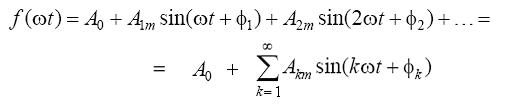
The first member of the series is called constant component , the second term is fundamental or first harmonic . The remaining members of the series are called higher harmonics .
If in the expression to reveal the sines of the sum of each of the harmonics, then it will take the form:
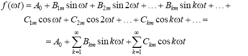
In the case of an analytical specification of the function f (ωt) series coefficients can be calculated using the following expressions:
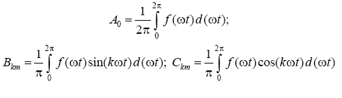
After that, the amplitudes and initial phases of the harmonic components of the series are calculated:

The coefficients of the Fourier series of most of the periodic functions encountered in technology are given in reference data or in textbooks on electrical engineering.
With a symmetrical load
U a = U V = U With = U A = U IN = U WITH = U f
Ia = iv = ic = I
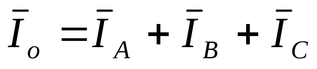
The sum of the instantaneous values of the currents of all three phases or the geometric sum of the vectors of these currents is equal to zero (Fig. 4).
There will be no current in the neutral wire with a four-wire star. Therefore, with a symmetrical load, there is no need to connect it.
asymmetrical load.
In the general case of unbalanced load Z a Z b Z With .
Unbalance can be caused by heterogeneity or uneven load.
An asymmetric load connected by a "star" is usually connected in a four-wire circuit, i.e. with a neutral wire, since in the presence of a neutral wire with low resistance, an asymmetric load does not lead to a significant change in the phase voltages. With some approximation, we can assume that the phase voltages remain the same as for the case of a symmetrical load.
U a = U b = U c = U A = U IN = U WITH
 .
.
An equalizing current flows through the neutral wire I o
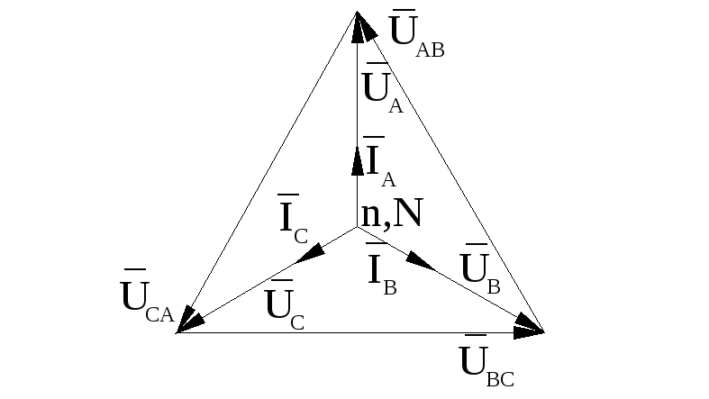
A vector diagram for an asymmetric phase load (active load, asymmetry is created by load unevenness) with a neutral wire is shown in fig. 5.
The absence of a neutral wire with an unbalanced load disrupts the normal operation of the installation.
The phase currents are varied and set such that their sum is zero. As a result, the symmetry of the phase voltages is distorted: the phase with less resistance is under reduced voltage, and with high resistance - under increased voltage, compared to normal.
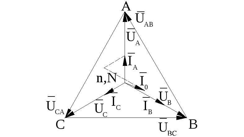
The vector diagram in the absence of a neutral wire is shown in fig. 6.

The construction of the diagram begins with an invariable triangle of linear voltages.
Generator zero ( N) is determined by the position of the center of gravity of the triangle, because generator phase voltages are symmetrical. Zero load point ( n) is defined as follows: from the point A compass solution, equal in scale to the value of the measured phase load voltage U A, a notch is made. The same serifs are made from the point IN compass solution U V, from the point WITH- solution U With. The intersection point of the serifs is the load zero. By connecting the zero point to the ends of the generator phases (i.e. A, B, C), construct phase load voltages U A , U V , U With. Depending on the nature of the load, current vectors are drawn. On fig. 6 shows a vector diagram of an uneven active load.
Line segment Nn= U 0 – neutral bias voltage can be measured with a voltmeter or calculated by the formula
 ,
,
Where  - complexes of effective values of phase voltages of the generator;
Y a , Y b , Y With are the complex conductivities of the load phases.
With a known neutral bias voltage, the phase voltages of the receiver can be calculated using the formulas:
 ,
,
 ,
, .
.
In the laboratory work, several cases of unbalanced load are considered, in particular, an open and short circuit of the receiver phase.
In the event of a phase failure A without a neutral wire with equal active resistances of the other two phases:  ,
,
 ;
;
 ;
;

The vector diagram is shown in fig. 7.
In case of phase short circuit A:
U a = 0,  ,
, ,
, .
.
The vector diagram is shown in fig. 8.

The active power of a three-phase current with an unbalanced load of the phases is equal to the sum of the active powers of all phases.
Since with a symmetrical load of phases and a symmetrical voltage system U a
=
U b
=
U With
=
U f ;
U AB
=
U sun
=
U SA
=
U L ;
cosφ a
= cosφ b
= cosφ c
=
cosφ f, That active power three-phase current is  .
.
So when connected with a "star"
 ;
;
 , .
, .
 (1 ratings, on average: 5,00 out of 5)

