Three-phase triangle circuit. Three-phase electrical circuits
Three-phase current circuits
Multiphase and three-phase systems. The principle of obtaining three-phase EMF
A multiphase power source is a set of EMFs of the same frequency, shifted relative to each other in phase. The combination of a multiphase source and a multiphase receiver forms a multiphase electrical circuit. Separate electrical circuits that are part of a multiphase system are called phases. Thus, phase is a twofold concept. On the one hand, this is a stage of a periodic process, on the other hand, it is part of a multiphase electrical circuit.
If the number of phases is m=3, we get a three-phase system. The three-phase system is the main one for power supply to enterprises. Thanks to its technical and economic characteristics, three-phase current provides the most economical transmission of electrical energy and allows the creation of simple, reliable and economical transformers, generators, and electric motors.
The fundamental research that led to the introduction of three-phase systems into practice was done by Nikola Tesla (origin - Austria-Hungary, now Croatia) and the Russian scientist Dolivo-Dobrovolsky.
Major inventions related to three-phase power supply systems were made and patented by Tesla. At the same time, the work of Dolivo-Dobrovolsky, who was the first to use three-phase current for industrial purposes, is of great theoretical and practical importance. All links of the three-phase circuit: transformers, generators, transmission lines and motors were developed by M.O. Dolivo-Dobrovolsky so deeply that they have not fundamentally changed to this day.
In some technical devices, two-phase, four-phase, and six-phase systems are used.
A three-phase EMF system is obtained in three-phase generators. Such a generator consists of a stator and a rotor. Three windings are placed in the stator slots, shifted relative to each other in space by 120°. The rotor is made in the form permanent magnet or electromagnet. When it rotates, an EMF is induced in the windings, the graphs of instantaneous values of which are presented in Fig. 1
All EMFs of the considered system have equal amplitudes E m and are shifted relative to each other in phase by an angle of 120°. Such an EMF system is called symmetrical.
Three-phase symmetrical system
Taking the reference point at the moment when е a =0, we write down the instantaneous values of all emfs.
e L1 =E m *sinω t
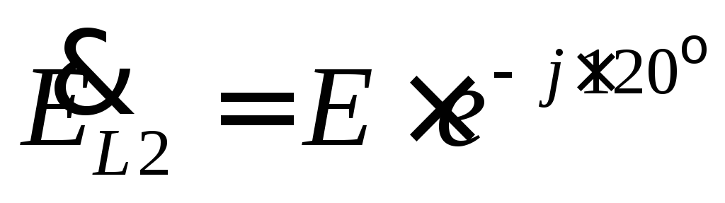
e L2 =E m *sin (ω t-120° )
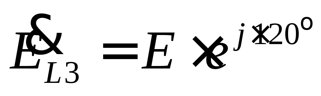
e L3 =E m *sin (ω t-240° )= E m *sin (ω t+120)
In symbolic form (as complex amplitudes):
 ,
,
 ,
,
 , Where
  .
.
Vector symmetrical diagram three phase system shown in Fig. 2.

A symmetrical three-phase system has the following properties:
 ,
,
 .
.
This property is also true for currents with a symmetrical load.
Types of three-phase circuit connections .
There are two main types of connection of the windings of transformers, generators, and receivers in three-phase circuits: star connection and delta connection.
The star connection between the source and receiver is shown in Figure 3.
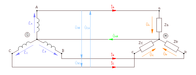
The voltages at the terminals of individual phases of the receiver or source are called phase voltages.  - phase voltages. The voltages between the line wires connecting the three-phase source to the receiver are called line voltages.
  - linear voltages. Currents flowing in the phases of the receiver or generator are called phase currents. Currents flowing in linear wires are called linear currents. Obviously, for a star connection the line currents
  are phase currents. The wire connecting the zero nodes of the source and receiver (nodes n, N) is called the zero (common, neutral) wire. According to Kirchhoff's current law, the current in the neutral wire is equal to
 .
.
With a symmetrical load, the currents in the phases are equal. Then
=
the current in the neutral wire will be zero. Therefore, when symmetrical load the source and load can be connected only by three linear wires.
In Fig. Figure 4 shows a vector diagram of the circuit in symmetrical mode and the active-inductive nature of the load, in which the currents lag behind the voltages.

Let us establish the relationship between linear and phase voltages. Line voltages are defined as the differences in phase voltages.
 ;
;
 ;
; .
.
From the isosceles triangle ANB it follows
 .
.
In Fig. Figure 5 shows a triangle connection between source and receiver.
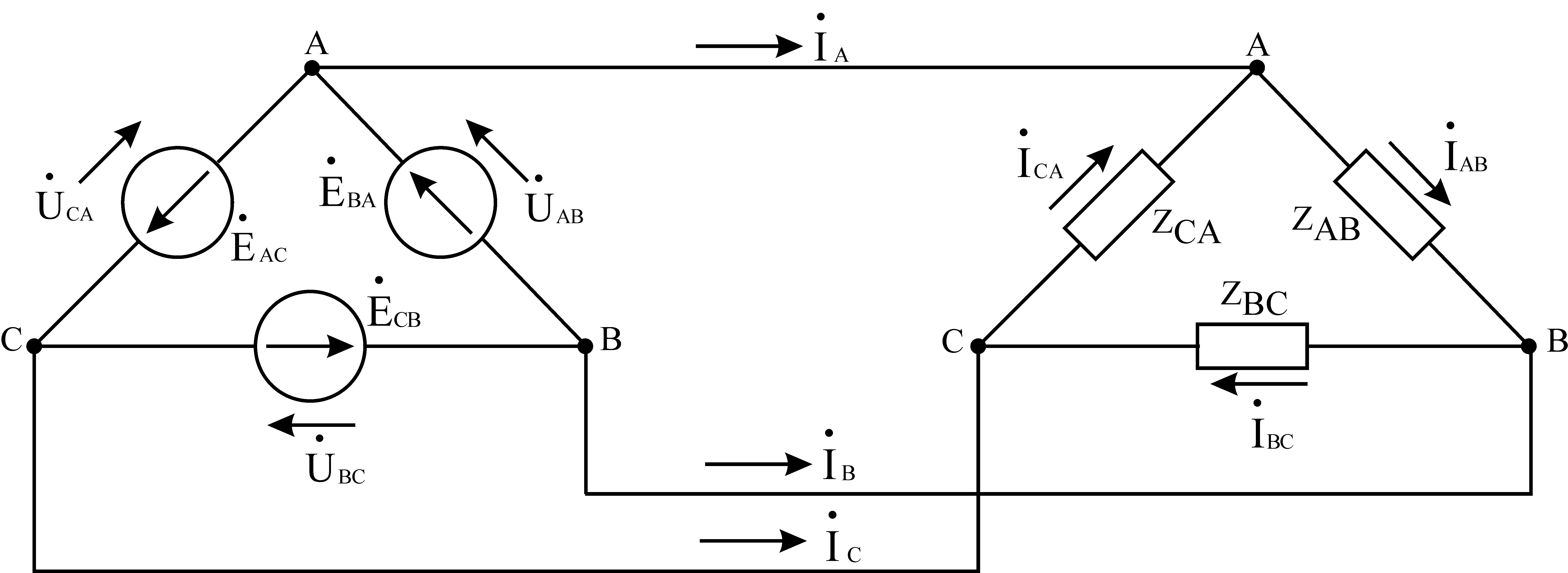
With this type of connection, phase EMFs are connected in series. The common points of each pair of phase EMFs and the common points of each pair of receiver branches are connected by linear wires. At first glance, such a connection of phase EMF is an emergency short-circuit mode. However, we should not forget that the sum of the instantaneous values of the EMF of a three-phase symmetrical source at any time is zero.
In Fig. Figure 6 shows vector diagrams of voltages and currents in symmetrical mode and an active-inductive load for a delta connection.

Linear currents are defined as the differences in phase currents:
 ;
;
 ;
; .
.
Wherein:
 ;
;
 .
.
Calculation of three-phase circuits with an asymmetric load.
The calculation of a three-phase circuit when connecting a source to a receiver in a triangle does not contain anything fundamentally new compared to the calculation of a conventional sinusoidal current circuit. In the circuit in Fig. 5 we find phase currents:
 ;
;
 ;
; .
.
Based on the found phase currents, we determine line currents based on Kirchhoff's current law:
;
;.
A three-phase circuit is calculated similarly when the source and receiver are connected by a star with a neutral wire (Figure 3). According to Ohm's law, we determine the phase currents:
 ;
; ;
; .
.
The phase currents for a star connection are linear currents. The current in the neutral wire is determined according to Kirchhoff's current law:
.
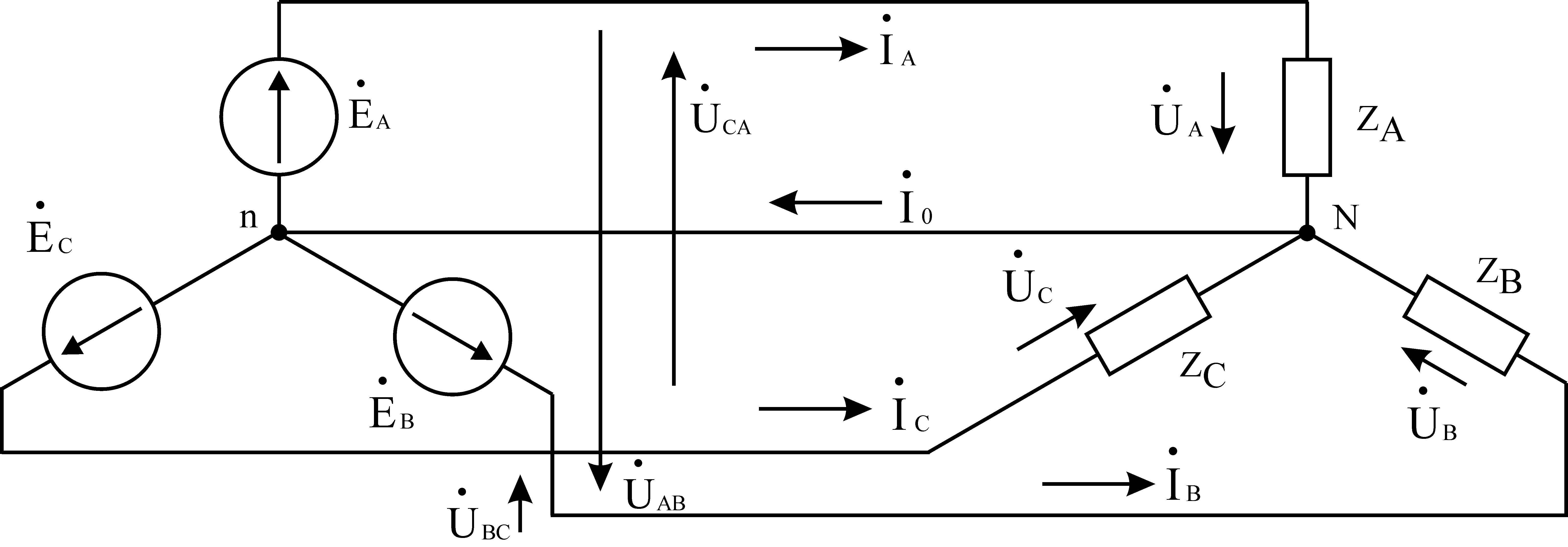
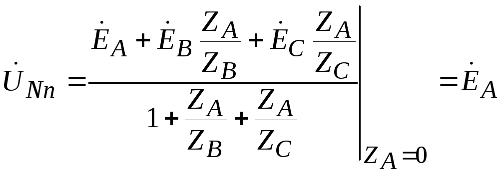
To calculate an asymmetrical three-phase circuit when connected by a star with a three-wire line, we use the two-node method.
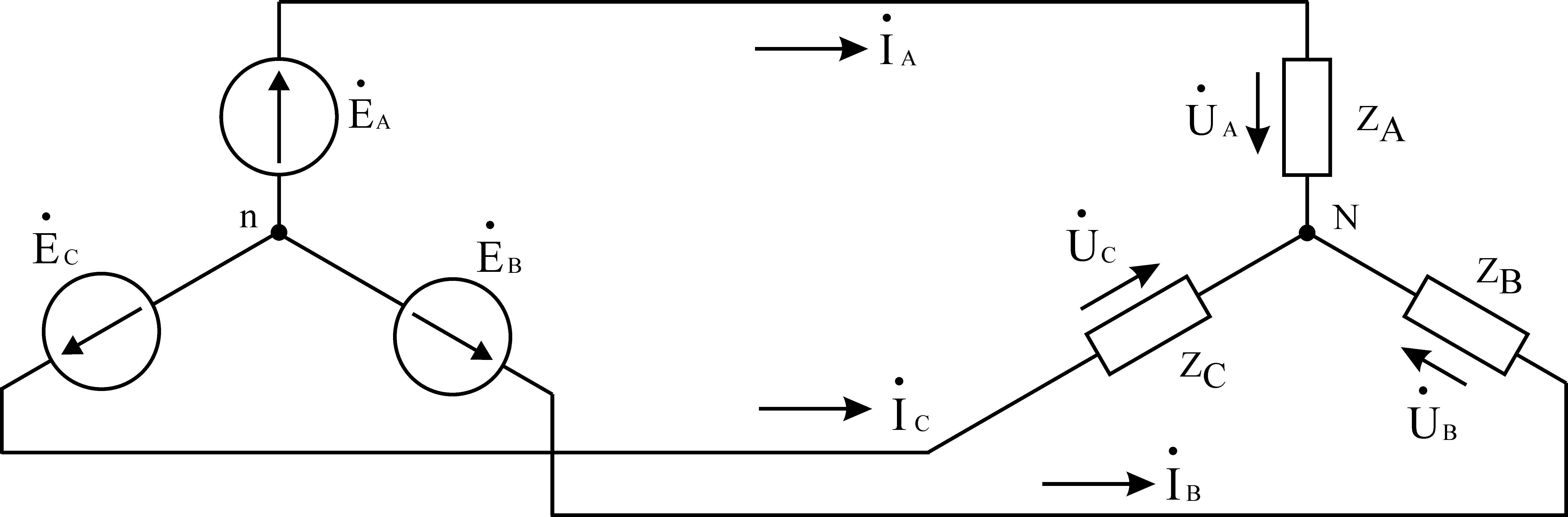
Rice. 7
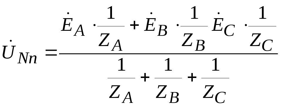
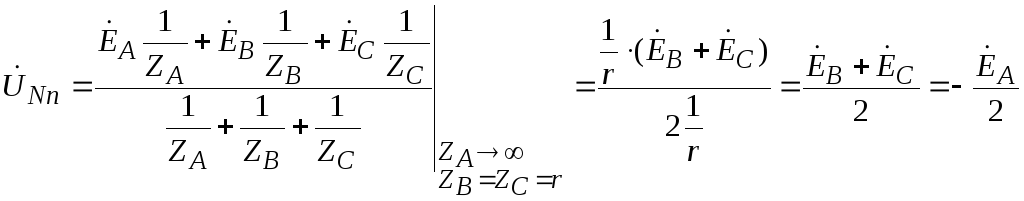
Let's determine the voltage between the zero points of the source and load -  , which is called the neutral bias voltage.
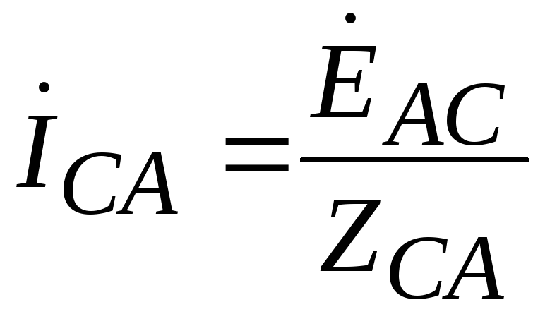
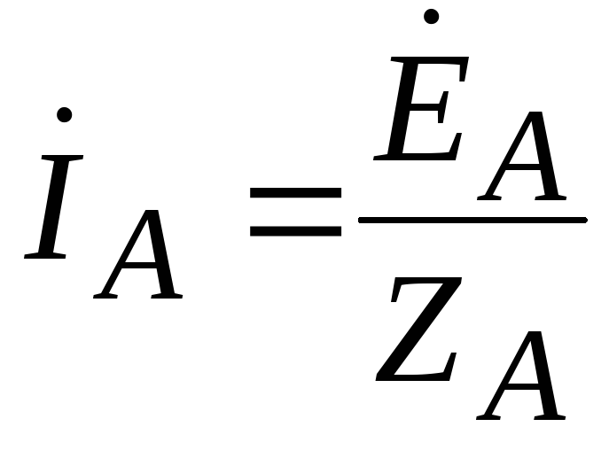
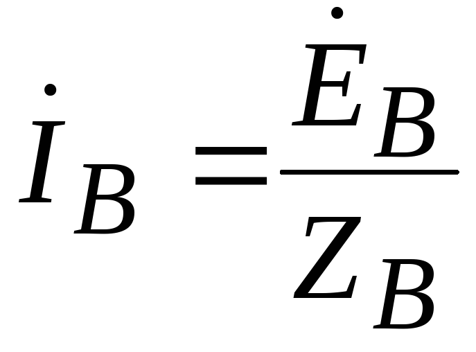
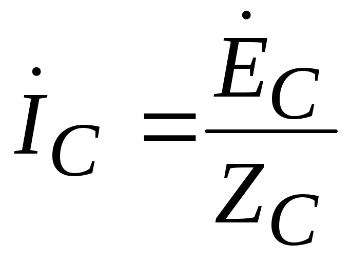
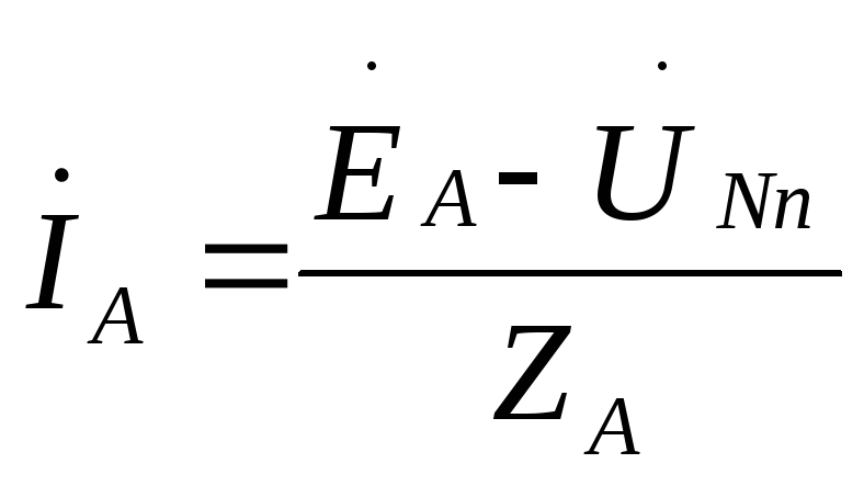
Knowing the tension  , let’s determine linear (aka phase) currents according to Ohm’s law for the section of the circuit with EMF:
=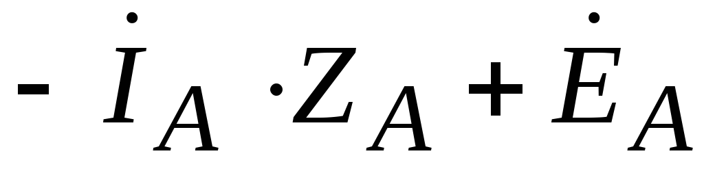 ,
,
 .
.
Likewise


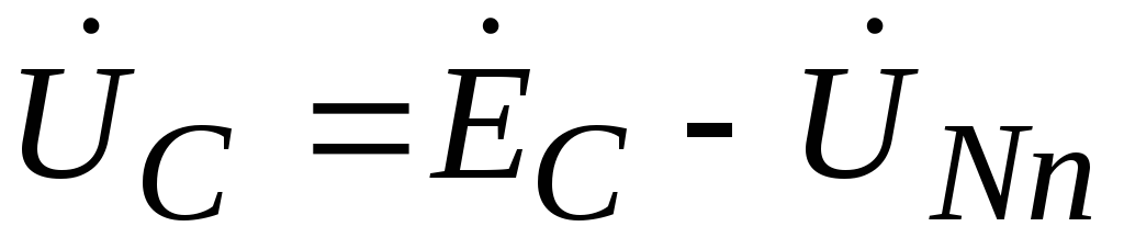
The voltage at the load phases will be equal to:
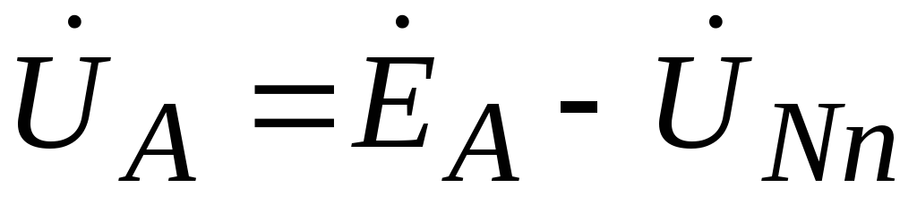 ,
,
 ,
,
 .
.
Let's consider two special cases of asymmetric load.
1) Short circuit of one of the load phases with equal resistance in the other two phases.
 ,
,
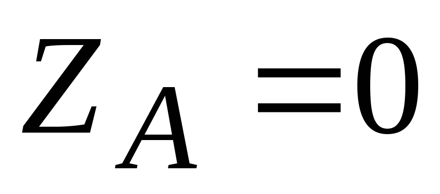 .
.
Neutral bias voltage we determine by a well-known expression, having previously multiplied its numerator and denominator by  .
.
 ,
,
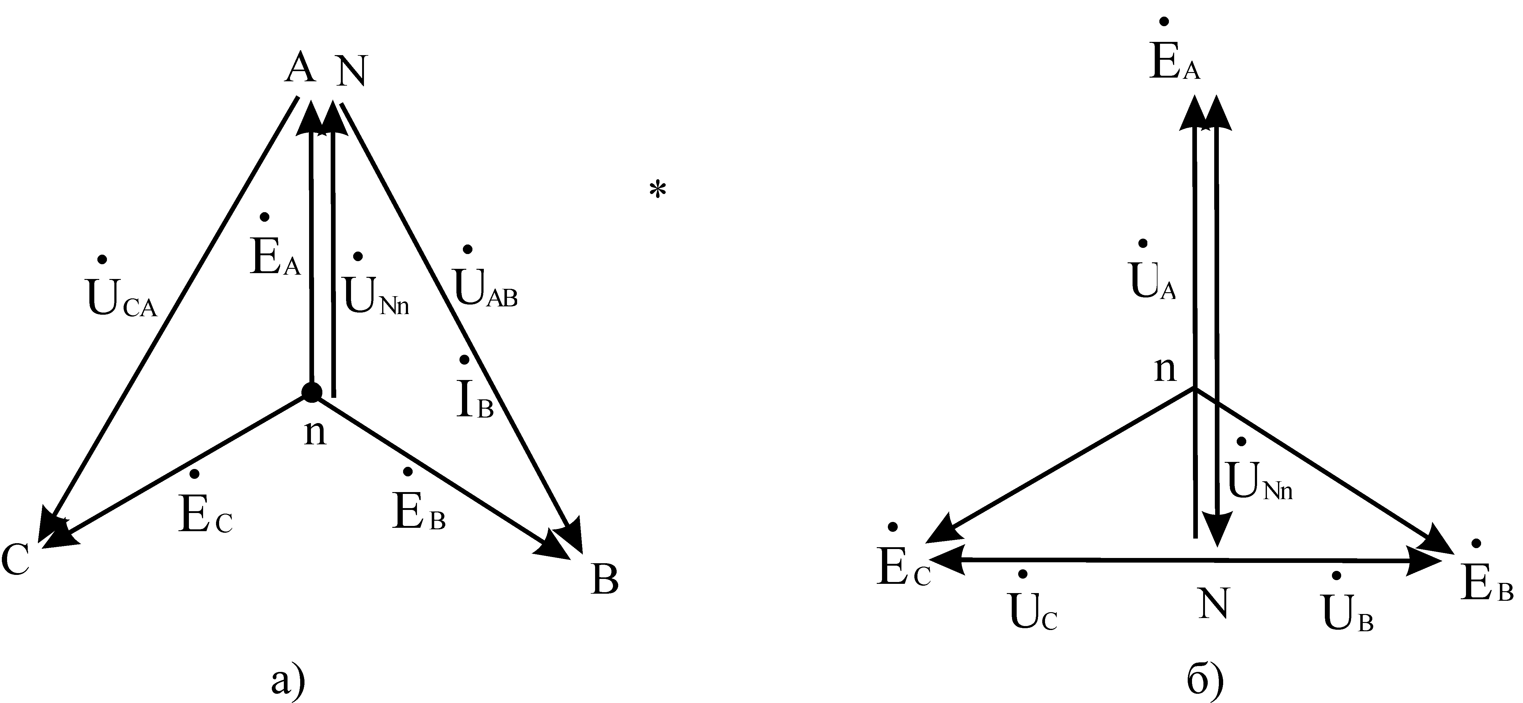
Thus, during a short circuit, the load is in phase A, the voltage on it becomes zero, and the voltages on the phases IN And WITH the loads increase to linear, i.e. V  once. The neutral bias voltage for this case will be equal to the phase voltage. The vector diagram for this case is shown in Fig. 8a.
2) An open circuit in one of the load phases with equal resistance in the other two phases.
 ,
,
 .
.
The neutral bias voltage for this case will be equal to:
The voltages at the load phases will be equal to:
,
,
Thus, in the event of a phase failure A load, the voltage in it becomes 1.5 times greater than the phase voltage, the voltage on the phases IN And WITH loads decrease and become equal to half line voltage, the neutral bias voltage becomes equal to half the phase voltage.
The vector diagram for this case is shown in Fig. 8b
7.5.Power in a three-phase circuit and its measurement.
Considering that for a symmetrical three-phase star-connected circuit  ,
, , and for connected by a triangle
  ,
, , we get, regardless of the type of connection
Where  - phase shift between phase voltage and phase current (cosφ – power factor).
Similarly, for reactive and apparent powers with a symmetrical load, we obtain:
In the case of an asymmetrical load, the powers are calculated for each of the load (source) phases separately and then added up.
To measure power in a four-wire three-phase circuit connected by a star, wattmeters are connected according to the diagram shown in Fig. 7.9.

The total power consumed by the load will be equal to the sum of the readings of three voltmeters connected to the phases A, B And WITH. In a three-wire circuit, two wattmeters are used, connected according to the diagram shown in Fig. 7.10.
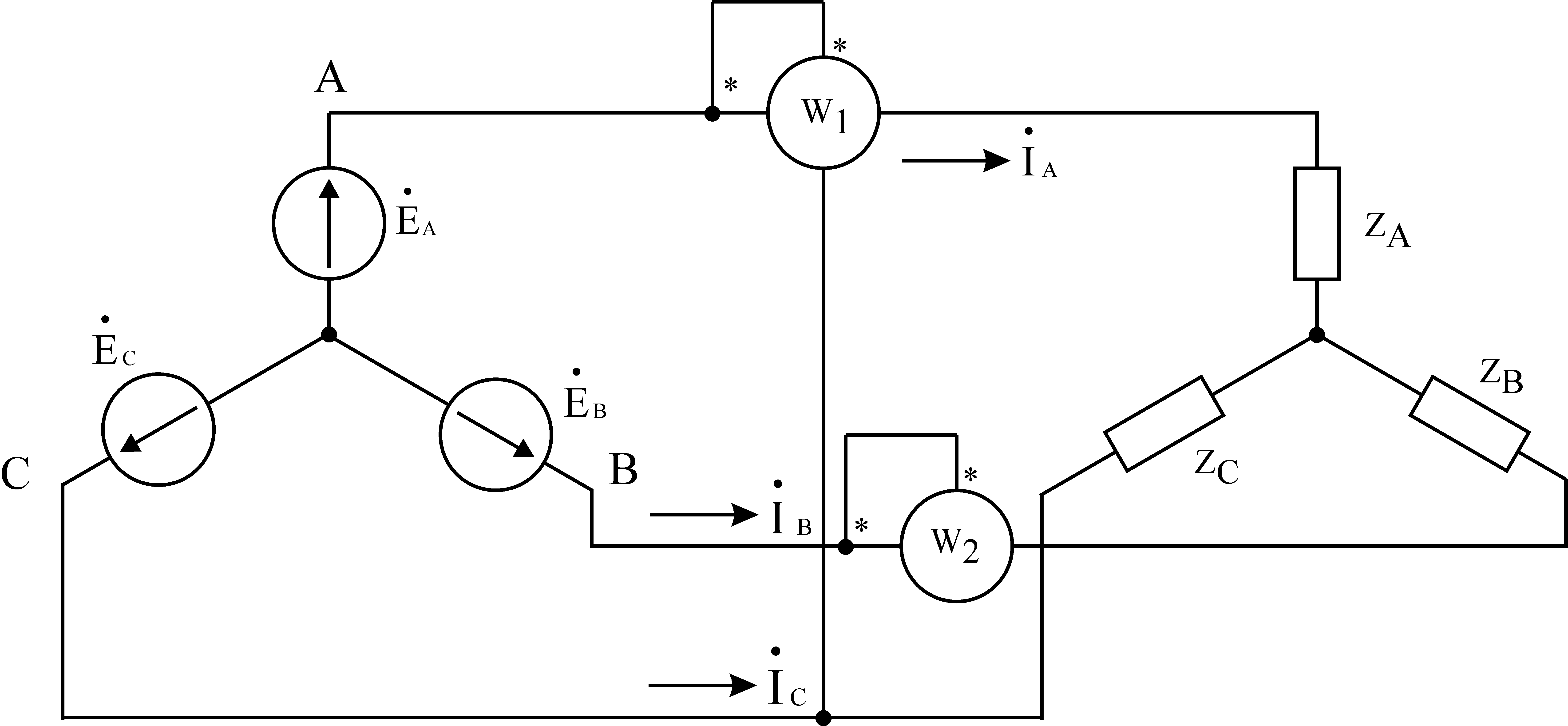
Let us show that the power displayed by two wattmeters will be equal to full power three-phase circuit (the so-called two-wattmeter circuit, or Aaron's circuit).
§ 5.1. General information.
Three sinusoidal EMFs of the same frequency and amplitude, shifted in phase by 120°, form a three-phase symmetrical system. Three-phase voltage and current systems are obtained similarly.
Currently, three-phase systems are widespread, which is mainly due to the following reasons:
1. at the same voltages, consumer powers and other equal conditions, three-phase current supply allows for significant savings in wire materials compared to three single-phase lines;
2. all other things being equal, a three-phase generator is cheaper, lighter and more economical than three single-phase generators of the same type total power, the same applies to three-phase motors and transformers;
3. Three-phase current system allows you to obtain a rotating magnetic field using three fixed coils, which greatly simplifies production and operation three-phase motors;
4. With a uniform load, a three-phase generator creates a constant torque on the drive motor shaft, in contrast to a single-phase generator, in which the power and torque on the shaft pulsate at double the current frequency.
§ 5.2. The principle of obtaining three-phase EMF. Basic connection diagrams for three-phase circuits.
Fig.5-1. Scheme of the simplest three-phase generator.
Figure 5-1 shows a diagram of the simplest three-phase generator, with the help of which it is easy to explain the principle of obtaining a three-phase EMF. In a uniform magnetic field of a permanent magnet, three frames rotate at a constant angular velocity ω, shifted in space one relative to the other by an angle of 120°.
At time t=0, the AX frame is located horizontally and an EMF is induced in it
![]() .
.
Exactly the same EMF will be induced in frame BY when it rotates 120° and takes the position of frame AX. Therefore, at t=0
Reasoning in a similar way, we find the EMF in the CZ frame:
Figure 5-2 shows a vector diagram of a three-phase EMF system.

Fig.5-2. Vector diagram of a three-phase EMF system.
Any three-phase generator (industrial) is a source of three-phase symmetrical EMF, which means equality:
1. amplitude values induced EMF in phases A, B, C;
2. they are all displaced e A, e B, e C relative to each other by an angle of 120°.
If a load is connected to each of the frames AX, BY and CZ (using brushes and slip rings), then currents will appear in the resulting circuits.
Vector diagram three-phase voltages and currents with a symmetrical load is shown in Fig. 5-3.

In a three-phase circuit, a three-phase system of currents flows, i.e. sinusoidal currents with three different phases. The section of the circuit through which one of the currents flows is called phase of a three-phase circuit.
Possible various ways connection of the generator windings to the load. Figure 5-4 shows a disconnected three-phase circuit in which each generator winding supplies its own phase load. Such a circuit, which requires 6 connecting wires, is practically never used.

Fig.5-4. Unconnected three-phase circuit.
On electrical diagrams A three-phase generator is usually depicted as three windings located at an angle of 120° to each other.
When connected by a star (Fig. 5-5), the ends of these windings are combined into one point, which is called the zero point of the generator and is designated O. The beginning of the windings is designated by the letters A, B, C.


When connected by a triangle (Fig. 5-6), the end of the first winding of the generator is connected to the beginning of the second, the end of the second to the beginning of the third, the end of the third to the beginning of the first. The connecting line wires are connected to points A, B, C.
In a three-phase circuit, according to GOST, the following voltage values are established for power circuits: 127; 220; 380; 660 V and above. All of them differ from the nearest figure by a factor.
§ 5.3. Star connection of generator and consumer windings.

To connect a generator (consumer) with a star means to connect into one common point, called null(N – for the generator, N’ – for the consumer), ends of the phases of the generator (consumer) winding. ABC is the beginning of the generator winding phases, XYZ is the end of the generator winding phases.
Phase is the voltage measured between the beginning and end of the generator (consumer) phase or between the linear and neutral wires.
Line wire– a wire connecting the beginning of the generator phases to the consumer.
The wire connecting the generator zero (N) to the consumer zero is designated U A, U B, U C or U Ф.
Linear is the voltage measured between the beginnings of phases or between linear wires. Designated U AB, U BC, U CA or U L.
There is a relationship between the phases of linear voltage (their vector form)

Vector diagrams of phase and line voltages of the generator of three phase current(it is also valid for a three-phase consumer with a symmetrical load).
The procedure for constructing a vector diagram for any load:
The diagram must be drawn to scale. When choosing a scale, it should be remembered that the lengths of the phase current vectors should be somewhat less than the corresponding phase voltage vectors. The construction of the diagram begins:
1. Phase voltage vectors , , ; are laid out at an angle of 120° relative to each other.
2. taking into account the phase shift angles φ A, φ B, φ C, the phase current vectors , , ;
3. the current vector in the neutral wire (for a symmetrical load it is not found, since I N = 0) is found from the expression of Kirchhoff’s first law for the vector form of currents
![]() .
.

Here U A =U B =U C ; U AB =U BC =U CA . By definition of cosine  , from here
 ![]() , , i.e. .
, , i.e. .
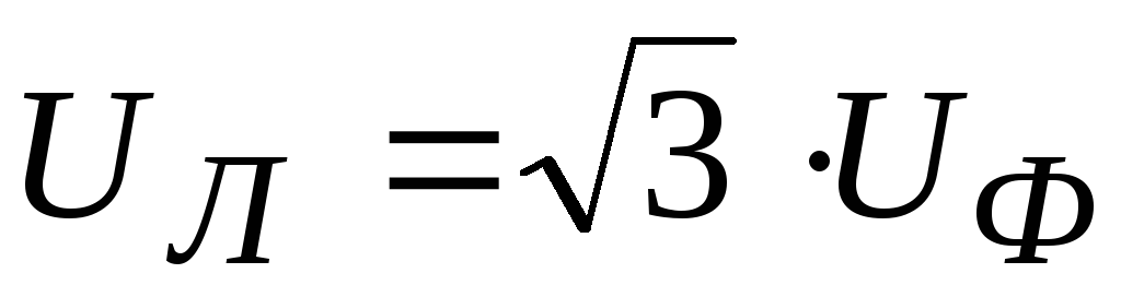
When connected by a star, the linear voltage of the generator is times greater than the phase voltage. This statement is true for symmetrical load three-phase consumers connected by a star.
Symmetrical is called a load at which:
1. Z A =Z B =Z C ;
2. φ A =φ B =φ C, where φ is the phase shift angle;
3. in each phase the nature of the voltage must be the same, i.e. it must be active, capacitive, inductive, active-inductive, active-capacitive in all phases.
When connected by a star, the line and phase current are the same current
Neutral wire and its role.
It is needed to obtain such a connection diagram when the load is asymmetrical. By using neutral wire with an asymmetrical load, the phase voltages of the consumers are equalized. If there is no neutral wire (break, mechanical damage) where the load is less, the voltage will be greater and vice versa.
A neutral wire is not needed if the load is symmetrical. A striking example such loads are three-phase asynchronous motors. The cross-section of the neutral wire and the linear wire is almost the same.
§ 5.4. Connection of the generator and consumer windings with a triangle.

e AB , e BC , e CA – instantaneous EMF values induced in phases A, B, C of the synchronous generator.
For such a connection, it is necessary to connect phase A of the generator (the beginning of the phase) to the end of phase C, i.e. with point Z; connect the beginning of phase B to the end of phase A (point X) and connect the beginning of phase C (point C) to the end of phase B (point Y). Therefore, with such a connection, the phase voltage of the generator (consumer) is equal to the linear voltage of the generator (under normal operating conditions of such a circuit).
Therefore, when connecting consumers according to a delta circuit, its phase voltage is always equal to the linear voltage of the generator, does not depend on the size and nature of the load, etc. The generator voltage is maintained constant using automatic regulators, then the phase voltage of the consumer is also constant. As can be seen from the generator connection diagram, its three phases form a closed circuit with negligible resistance. Therefore, in order to prevent overheating of the winding, the occurrence short circuit it is necessary that e AB +e BC +e CA is always equal to 0. Therefore, incorrect connection of the generator winding is dangerous (confusing the beginning with the end), which will lead to a short circuit.
For the consumer.
Let's compose expressions connecting the phase and linear currents of the consumer, applying Kirchhoff's first law. Then, for consumer branch points according to Kirchhoff’s first law
 (1)
(1)
Let us derive the relationship between the linear and phase currents of consumers connected by a triangle for the case of a symmetrical load. What will we use it for? vector diagram and expressions (1), on the basis of which this diagram is constructed.
Construction order:
1. at an angle of 120° with respect to each other, we will plot the vectors of phase currents, and I AB =I BC =I CA - this is how phase currents are designated;

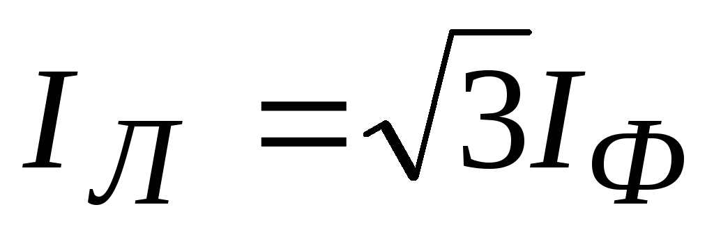
2. to find the values of linear currents, you must now connect the vertices of the phase current vectors and set aside the vector (arrow) taking into account expression (1). We obtained an equilateral triangle ABC, where the vectors of linear currents , , are equal to each other. From an isosceles triangle we have that the perpendicular DM will also be the bisector and the median. Then CM divided by I CA is equal to cos30°, hence, i.e., if the loads are symmetrical, the linear current is always greater than the phase current by a factor, i.e. .
Currently, electronic energy alternating current is generated, transmitted and distributed between individual current collectors in a three-phase circuit system.
A three-phase circuit system is a combination of electronic circuits in which the current collectors receive power from a common three-phase generator.
A three-phase generator is one that has a winding consisting of three parts. Any part of this winding is called a phase. That's why these generators got the name three-phase
. It should be noted that the term “phase” in electrical engineering has two meanings:
1) in the sense of a certain stage of a repeating oscillatory process and
2) as the name of a part of an electronic alternating current circuit (for example, part of the winding of an electronic machine).

Rice. 1. Three-phase generator circuit
To understand the principle of operation of a three-phase generator, let us turn to the model schematically depicted in Figure 1. The model consists of a stator made in the form of an iron ring and a rotor - a permanent magnet. The stator ring contains a three-phase winding with a similar number of turns in each phase. The phases of the winding are shifted in space one relative to the other by an angle of 120°.
Let us imagine that the rotor of the generator model is rotated at a constant speed counterclockwise. Then, due to the continuous movement of the poles of a constant magnet relative to the conductors of the stator winding, an emf will be induced in each phase.
Applying the rule right hand, we can be convinced that the emf induced in the winding phase by the north pole of a rotating magnet will act in one direction, and that induced by the south pole in the other. As follows, e.m.f. the generator phase will be variable.
The last points (clamps) of each phase of the generator are always marked: one extreme point of the phase is called the beginning
, and the other - the end
. The beginnings of the phases are indicated by Latin signs A, B, C,
and their ends respectively - X, Y, Z.
The names “beginning” and “end” of the phase are given based on the following rule: positive e. d.s. The generator acts in the direction from the end of the phase to its beginning.
E.m.f. We agree to consider the generator positive if it is induced by the north pole of a rotating magnet. Then the marking of the generator terminals for the option of rotating its rotor counterclockwise should be as shown in Figure 1.
At a constant speed of rotation of the rotor poles, the amplitude and frequency of the emf created in the phases of the stator winding remain constant. But at every moment the magnitude and direction of the emf action. one of the phases differs from the magnitude and direction of the emf. 2 other phases. This is explained by the spatial phase shift. All phenomena in the 2nd phase repeat the phenomena in the first phase, but with a delay. They say that e. d.s. The 2nd phase lags behind the emf in time. first phase.
They, for example, achieve their own amplitude values at different times. Indeed, highest value The e.m.f. induced in any phase will be when the center of the rotor pole passes the middle of this phase. Namely, for the moment of time corresponding to the location of the rotor shown in Figure 1, electromotive force the first phase of the generator will be positive and largest. Positive maximum emf value. The 2nd phase will occur later, when the rotor rotates through an angle of 120°. Since during one revolution of a two-pole generator rotor a complete cycle of emf configuration occurs, the time T of the 1st revolution is the period of emf configuration. Of course, to rotate the rotor 120° it takes a time equal to one third of the period (T/3).
As follows, all stages of the emf configuration. The 2nd phases occur later than the corresponding stages of the emf configuration. the first phase for one third of the period. The same lag in the repeated change in emf. observed in the third phase in relation to the 2nd. Of course, with respect to the first phase, repeating configurations of the emf. the third phases occur with a delay of two-thirds of the period (2/3 T).
By giving the appropriate shape to the poles of the magnets, the emf configuration can be achieved. in time according to a law close to sinusoidal.
As follows, if the change in e.m.f. the first phase of the generator occurs according to sine law
e1 = Emsin?t,
then the law of emf configuration The 2nd phase can be written by the formula
e2 = Em sin? (t ? T/3)
,

Rice. 2. Curves of instantaneous values of a three-phase E.M.F. system.
and the third – by the formula
e3 = Em sin? (t ? 2/3 T)
,
This is illustrated by the graph in Figure 2.
Thus, we can draw the following conclusion: with uniform rotation of the rotor poles, variable emfs are induced in all 3 phases of the generator. similar frequency and amplitude, repeating configurations of which in relation to each other occur with a delay of 1/3 of the period.
A three-phase generator serves as a power source for both single-phase and three-phase electronic devices. Single-phase current collectors, as is clear, have two external terminals. These include, for example, lighting lamps, different Appliances, electric welding machines, induction furnaces, electric motors with single-phase winding.
Three-phase devices generally have 6 external terminals. Each such device consists of 3, usually similar, electronic circuits, which are called phases. Examples of three-phase current collectors include electronic arc furnaces with 3 electrodes or electric motors with three-phase winding.
Methods for connecting the phases of the generator and current collector
A three-phase circuit is called unconnected if any phase of the generator is independently connected by 2 wires to its current collector (Fig. 3). The main disadvantage of an uncoupled three-phase circuit is that 6 wires must be used to transfer energy from the generator to the receivers. The number of wires can be reduced to 4 or even 3 if the phases of the generator and pantographs are connected to each other using a suitable method. In this case, the three-phase circuit is called connected by a three-phase circuit
.

Fig.3. Unconnected three-phase circuit diagram
In practice, connected three-phase circuits are almost always used, as they are more advanced and economical. There are two main methods for connecting generator phases and receiver phases: star connection
And delta connection.
When connecting the generator phases with a star (Fig. 4, a) all “ends” of phase windings X, Y, Z are connected to one common point 0
, called neutral
or null
generator point.
Figure 4, b schematically shows three phases of the generator in the form of coils, the axes of which are shifted in space one relative to the other at an angle of 120°.
The voltage between the beginning and end of each phase of the generator is called phase voltage
, and between the beginnings of the phases – linear.
Since phase voltages change over time according to a sinusoidal law, line voltages will also change according to a sinusoidal law. Let us agree that the positive direction of action of linear stresses is the direction in which they act:

Fig.4. Three-phase winding, connected by a star: a – connection diagram, b – winding diagram
star: a – connection diagram, b – winding diagram
from terminal A of the first phase to terminal B of the 2nd phase;
from terminal B of the 2nd phase to terminal C of the third phase;
from terminal C of the third phase to terminal A of the first phase.
These three conditionally positive directions of action of linear stresses in Figure 4, b are shown by arrows.
Calculations and measurements demonstrate that the effective value of the linear voltage of a generator, the three phases of which are connected in a star, is v3 times greater effective value phase voltage.
To transfer energy from a star-connected generator to single-phase or three-phase current collectors, in general, four wires are needed. Three wires are connected to the beginning of the generator phases (A, B, C
). These wires are called line wires.
The 4th wire is connected to the neutral point (0) of the generator and is called neutral (neutral) wire
.
A three-phase circuit with a neutral wire makes it possible to use two generator voltages. Receivers in such a circuit can be connected between linear wires for line voltage or between linear wires and a neutral wire for phase voltage.

Fig.5. Four-wire three-phase circuit
Figure 5 shows the connection diagram for current collectors designed for the phase voltage of the generator. In this case, the phases of the pantographs will have a common connection point - the neutral point 0?, and the currents in the linear wires (linear currents) will be equal to the currents in the corresponding load phases (phase currents).
Any load phase can be formed by either one pantograph or several pantographs connected in parallel to each other (Fig. 6).
If the phase currents and the phase angles of these currents with respect to the phase voltages are similar, then such a load is called symmetrical
. If at least one of the indicated criteria is not met, then the load will be asymmetrical
.
A symmetrical load can be created, for example, by incandescent lamps of similar power. Let us assume that any load phase is formed by 3 similar lamps (Fig. 7).
Using the method of specific measurements, you can verify that when the load is turned on by a star with a neutral wire, the voltage on each phase of the load Uph will be less than the linear voltage Ul by v3 times, just as it was when the phases of the generator windings were turned on by a star.

Fig.6. Scheme for connecting single-phase current collectors to a four-wire network
Ul = v3Uф
In practice, three-phase circuits with neutral wires at voltages
Ul = 380 V; Uph = 220 V
or
Ul = 220 V; Uph = 127 V
From Figure 7 it is clear that the current in the linear wire (Il) is equal to the current in the phase (Iph)
Iл = Iф
The magnitude of the current in the neutral wire with a symmetrical load is zero, which can also be verified by a specific measurement method.
But if there is no current in the neutral wire, then what is this wire needed for?

Rice. 7. Symmetrical star load connection diagram
To clarify the role of the neutral wire, we will perform the following experiment. Let us assume that in each load phase there are three similar lamps and one voltmeter, and in neutral wire The ammeter is turned on (see Fig. 7). When three lamps are turned on in each phase, they are all under the same voltage and glow with a similar intensity, and the current in the neutral wire is zero. By changing the number of lamps turned on in each load phase, we will make sure that the phase voltages do not change (all lamps will glow with the same slope), but a current will appear in the neutral wire.
Let's disconnect the neutral wire from the zero point of the receivers and repeat all load configurations in phases. Now we will notice that the greater voltage will fall on the phase whose resistance is greater than the others, in other words, where the least number of lamps are turned on. In this phase, the lamps will glow with great intensity and may even burn out. This is explained by the fact that in load phases with huge resistance, a larger voltage drop occurs.

Rice. 8. Diagram of the lighting network of a house when connecting the load phases with a star
As follows, a neutral wire is needed to equalize the phase voltages of the load when the resistances of these phases are different.
Thanks to the neutral wire, any load phase is switched on to the phase voltage of the generator, which actually does not depend on the magnitude of the load current, because the internal voltage drop in the generator phase is not cardinal. Therefore, the voltage at each load phase will be virtually constant under load configurations.
If the load phase resistances are equal in value and uniform, then a neutral wire is not needed (Fig. 7). An example of such a load is symmetrical three-phase current collectors.
Typically, the lighting load is not symmetrical, therefore, without a neutral wire, it is not connected with a star (Fig. 8). Otherwise, this would lead to an uneven distribution of voltages in the load phases: on some lamps the voltage would be higher than usual and they could burn out, while others, on the contrary, would be under low voltage and would burn dimly.
For the same reason, they never place a fuse in the neutral wire, because blowing the fuse can cause unacceptable overvoltages in individual load phases (see Fig. 8).

Rice. 9. Three-wire three-phase circuit
If three phases of the load are connected directly between the linear wires, then we get such a connection of the phases of the current collectors, which is called delta connection
(Fig. 9). Let us assume that the 1st phase of the load R1 is connected between the first and second linear wires; The 2nd R2 is between the second and third wires, and the 3rd R3 is between the third and first wires. It is easy to see that each line wire is connected to 2 different phases loads.
You can connect any loads with a triangle. Figure 10 shows
such a scheme.

Rice. 10. Diagram of the lighting network of a house when connecting the load phases with a triangle
The triangle connection of the lighting load of a house is shown in Figure 11. When connecting the load phases with a triangle, the voltage on each load phase is equal to the line voltage.
Ul = Uф
This ratio is maintained even under uneven load.
The line current with a symmetrical phase load, as measurements demonstrate, will be v3 times greater than the phase current
Iл = v3·Iф
But it should be understood that with an asymmetrical load of the phases, this relationship between the currents is violated.
In principle, it is possible to connect the generator phases with a triangle, but this is usually not done. The fact is that in order to create this

Rice. 11. Diagram of the lighting network of a house when connecting the load phases with a triangle
line voltage, any phase of the generator when connected by a delta must be
designed for a voltage v3 times greater than in the case of a star connection. Higher voltage in the generator phase requires an increase in the number of turns and increased insulation for winding wire, which increases the size and price of the machine. That's why the phases three-phase generators They are almost always connected with a star.
Receivers of electronic energy, regardless of the method of connecting the generator windings, can be connected either in a star or in a delta. The choice of one or another connection method is determined by the magnitude of the network voltage and rated voltage receivers.
 (1 ratings, on average: 5,00 out of 5)

