The windings of a three-phase generator are connected in a star. Options for connecting windings of three-phase generators
When connecting the windings in a star, the ends of the windings X, Y, Z are connected to one point, called the zero point or neutral of the generator (Fig. 7-5). In a four-wire system, the neutral or neutral wire is connected to the neutral. Three linear wires are connected to the beginning of the generator windings.
The voltages between the beginnings and ends of the phases, or, what is the same, the voltages between each of the linear wires and the neutral wire are called phase voltages and are designated or general view
Neglecting the voltage drop in the generator windings, we can consider the phase voltages equal to the corresponding e. d.s. induced in the generator windings.
The voltages between the beginnings of the windings, or, what is the same, between linear wires, are called linear voltages and are designated or in general form
Let us establish the relationship between linear and phase voltages when connecting the generator windings with a star.

Rice. 7-5. Star connection diagram of generator windings.

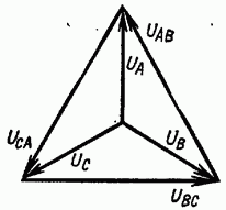
Rice. 7-6. Vector diagram of three-phase circuit voltages.
Since the end of the first phase X is connected not to the beginning of the second phase, but to its end Y, which is similar to the counter connection of two sources of energy. d.s. at constant current, then the instantaneous value of the linear voltage between wires A and B will be equal to the difference in the corresponding phase voltages, i.e.
similarly instantaneous values of other linear voltages
Thus, the instantaneous value of the linear voltage is equal to the algebraic difference of the instantaneous values of the corresponding phase voltages.
Since they change according to a sinusoidal law and have the same frequency, then the linear voltages will change sinusoidally, and effective values linear voltages can be determined from the vector diagram (Fig. 7-6):
From the above it follows that the linear voltage vector is equal to the difference between the vectors of the corresponding phase voltages.
Phase voltages are shifted from each other by 120°. To determine the linear voltage vector, you need to geometrically subtract the vector from the voltage vector, or, what is the same, add a vector - equal in magnitude and opposite in sign.
Similarly, we obtain the linear voltage vector as the difference between the voltage vectors and the linear voltage vector as the difference between the vectors and OA.
By lowering the perpendicular from the end of an arbitrary phase voltage vector, for example, to the linear voltage vector, we obtain a right triangle OHM, from which it follows that
![]()
![]()
Rice. 7-7. Vector diagram of voltages when connecting the generator windings with a star.
From the vector diagram (Fig. 7-6) and the last formula it follows that the effective value of the linear voltage is several times greater than the effective value of the phase voltage and that the linear voltage is 30° ahead of the phase voltage; by the same angle the linear voltage leads the phase voltage and voltage-phase voltage
Adjacent, linear voltages are shifted relative to each other at the same angles (120°) as adjacent phase voltages. The star of the linear voltage vectors is rotated in the positive direction relative to the star of the phase voltage vectors at an angle of 30°.
It is necessary to pay attention to the fact that the obtained relationships between linear and phase voltages take place only with a symmetrical voltage system.
Since the linear voltage vectors are defined as the differences between the phase voltage vectors, by connecting the ends of the phase voltage vectors forming a star, we obtain a triangle of linear voltage vectors (Fig. 7-7).
Example 7-1. Determine the linear voltage of the generator if its phase voltage is 127 and 220 V.
If the phase voltage is 220 V, then
§ 63. Generator winding connections
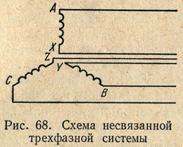
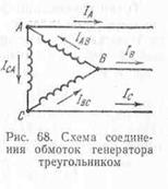
In Fig. Figure 68 shows a diagram of a generator that has three independent, mutually isolated single-phase circuits. E.m.f. in these circuits are identical, have the same amplitudes and are shifted in phase by 1/3 of the period. Wires that supply current to the load can be connected to each pair of generator stator winding terminals. It is more profitable to combine these three phases into one common three-phase system. To do this, the generator windings are connected to each other by a star or triangle.
star(Fig. 69) ends of all three phases X, Y And Z(or started A, IN And WITH) are connected to each other, and from the beginnings (or ends) wires are brought out, discharging energy into the network. The three wires thus obtained are called linear, and the voltage between any two linear wires is linear voltage U l. From common point connecting the ends (or beginnings) of the three phases (from the star zero point), a fourth wire, called zero. The voltage between any of the three linear wires and the neutral wire is equal to the voltage between the beginning and end of one phase, i.e. phase voltage U f.
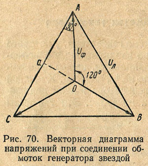
Typically, all phases of the generator winding are identical so that the effective values of e. d.s. in phases are equal, i.e. E A = E B = E C. If a load is connected to the circuit of each phase of the generator, then currents will flow through these circuits. In the case of the same magnitude and nature of the resistance of all three phases of the receiver, i.e., a symmetrical (uniform) load, the currents in the phases will be equal in strength and shifted in phase relative to their phase voltages by the same angle φ. Both the maximum and effective values of phase voltages under a uniform load are equal, i.e. U A = U B = U c. These voltages are 120° out of phase as shown in vector diagram(Fig. 70).
The voltage between any points of the circuit (see Fig. 69) corresponds to the vectors (see Fig. 70) between the same points. So, for example, the voltage between points A And O circuits (phase voltage U A) is represented by the vector JSC diagrams, and the voltage between the linear wires A And B circuit - linear voltage vector AB diagrams. Using a vector diagram, it is easy to establish the relationship between linear and phase voltages. From a triangle AOa we can write the following relation:
that is, when the generator windings are connected with a star, the linear voltage is times greater than the phase voltage (with a uniform load).
From the diagram (see Fig. 69) it is clear that when the generator windings are connected with a star, the current in the linear wire is equal to the current in the generator phase, i.e. I l = I f.
Based on Kirchhoff's first law, we can write that the current in neutral wire equal to the geometric sum of the currents in the phases of the generator, i.e.
With a uniform load, the currents in the generator phases are equal in magnitude, but are shifted in phase relative to each other by 1/3 of the period. The geometric sum of the currents of the three phases in this case is zero, i.e. there will be no current in the neutral wire. Therefore, when symmetrical load the neutral wire may be missing. Since the current in the neutral wire arises only due to load asymmetry, and usually this asymmetry is small, in most cases the neutral wire has a smaller cross-section than linear ones.
When connecting the generator windings triangle(Fig. 71) the beginning (or end) of each phase of the generator windings is connected to the end (or beginning) of the winding of another phase. Thus, the three phases of the generator form a closed circuit in which the electric current operates. d.c., equal to the geometric sum e. d.s. induced in the phases of the generator, i.e. ![]() . Since e. d.s. in the phases of the generator are equal and shifted by 1/3 of the period in phase, then their geometric sum is equal to zero, since the vectors of e. d.s. form a closed triangle and therefore in a closed loop three phase system, connected by a triangle, no internal current will arise.
. Since e. d.s. in the phases of the generator are equal and shifted by 1/3 of the period in phase, then their geometric sum is equal to zero, since the vectors of e. d.s. form a closed triangle and therefore in a closed loop three phase system, connected by a triangle, no internal current will arise.
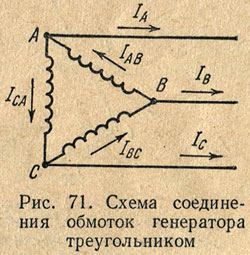
Linear wires, when connected in a triangle, are connected to the connection points of the beginning of one phase and the end of another. The voltage between line wires is equal to the voltage between the beginning and end of one phase. Thus, when the generator windings are connected with a triangle, the linear voltage is equal to the phase voltage, i.e. U l = U f.
With a uniform load, equal currents flow in the phases of the generator windings, shifted relative to the phase voltages by equal angles φ, i.e.
I AB = I BC = I CA.
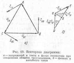
In Fig. 72, and a vector diagram is shown, which shows the vectors of phase voltages and currents.
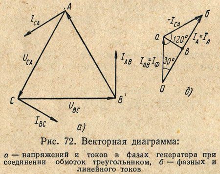
Connection points for phase and linear wires A, IN And WITH are branching points; line currents are not equal to phase ones. Taking the positive direction of phase and linear currents indicated in Fig. 70, based on Kirchhoff’s first law for instantaneous current values, the following expressions can be written:
Since the currents in the coils are sinusoidal, we replace the algebraic subtraction of the instantaneous current values with the geometric subtraction of vectors depicting their effective values.
To reduce the number of wires between the generator and the consumer, the phase windings must be connected to each other in a certain way, both in the generator and at the consumer. The generator windings are designated: U1 – U2,
V1 – V2, W1 – W2 (phases A, B, C). Index 1 indicates the beginning of the winding, index 2 indicates the end.
Generator winding connections
In Fig. Figure 68 shows a diagram of a generator that has three independent, mutually isolated single-phase circuits. E.m.f. in these circuits are identical, have the same amplitudes and are shifted in phase by 1/3 of the period. Wires that supply current to the load can be connected to each pair of generator stator winding terminals. It is more profitable to combine these three phases into one common three-phase system. To do this, the generator windings are connected to each other by a star or triangle.
When connecting the generator windings with a star (Fig. 69), the ends of all three phases X, Y and Z (or the beginnings of A, B and C) are connected to each other, and wires are brought out from the beginnings (or ends), discharging energy into the network. The three wires obtained in this way are called linear, and the voltages between any two linear wires are called linear voltages Ul. From the common point of connection of the ends (or beginnings) of the three phases (from the zero point of the star), a fourth wire, called neutral, can be drawn. The voltage between any of the three linear wires and the neutral wire is equal to the voltage between the beginning and end of one phase, i.e., the phase voltage Uph.
Typically, all phases of the generator winding are identical so that the effective values of e. d.s. in phases are equal, i.e. EA = EB = EC. If a load is connected to the circuit of each phase of the generator, then currents will flow through these circuits. In the case of the same value and nature of the resistance of all three phases of the receiver, i.e., a symmetrical (uniform) load, the currents in the phases will be equal in strength and shifted in phase relative to their phase voltages by the same angle φ. Both the maximum and effective values of phase voltages with a uniform load are equal, i.e. UA = UB = Uc. These voltages are 120° out of phase, as shown in the phasor diagram (Fig. 70).
The voltage between any points of the circuit (see Fig. 69) corresponds to the vectors (see Fig. 70) between the same points. So, for example, the voltage between points A and O of the circuit (phase voltage UA) is represented by the vector of the AO diagram, and the voltage between the linear wires A and B of the circuit is represented by the vector of the linear voltage of the AB diagram. Using a vector diagram, it is easy to establish the relationship between linear and phase voltages. From triangle AOa we can write the following relation:
that is, when the generator windings are connected with a star, the linear voltage is times greater than the phase voltage (with a uniform load).
From the diagram (see Fig. 69) it is clear that when the generator windings are connected with a star, the current in the linear wire is equal to the current in the generator phase, i.e. Il = Iph.
Based on Kirchhoff’s first law, we can write that the current in the neutral wire is equal to the geometric sum of the currents in the generator phases, i.e.
With a uniform load, the currents in the generator phases are equal in magnitude, but are shifted in phase relative to each other by 1/3 of the period. The geometric sum of the currents of the three phases in this case is zero, i.e. there will be no current in the neutral wire. Therefore, with a symmetrical load, the neutral wire may be absent. Since the current in the neutral wire arises only due to load asymmetry, and usually this asymmetry is small, in most cases the neutral wire has a smaller cross-section than linear ones.
Star connection
If the phase windings of a generator or consumer are connected so that the ends of the windings are connected to one common point, and the beginnings of the windings are connected to the linear wires, then such a connection is called a star connection and is designated conventional sign Y. In Fig. 1 windings of the generator and consumer are connected by a star. The points at which the ends of the phase windings of the generator or consumer are connected are called the zero points of the generator (0) and consumer (0’, respectively). Both points 0 and 0’ are connected by a wire called neutral, or neutral wire. The remaining three wires of the three-phase system, going from the generator to the consumer, are called linear wires. Thus, the generator is connected to the consumer by four wires. Therefore this system is called four wire system three-phase current.
Comparing the unconnected and four-wire three-phase current systems, we see that in the first case, the role of the return wire is performed by three wires of the system, and in the second - one neutral wire. A current flows through the neutral wire equal to the geometric sum of the currents:
IA, IB and IC, i.e. Ī0= ĪA + ĪB + ĪC.
The voltages measured between the beginnings of the phases of the generator (or consumer) and the zero point (or neutral wire) are called phase voltages and are designated UA, UB and UC, or in general Uph. The emf values are often specified. generator phase windings. They are designated EA, EB and EC, or Eph. If we neglect the resistance of the generator windings, we can write:
EA= UA, EB= UB, EC= UC.
Voltages measured between the beginnings of two phases: A and B, B and C, C and A - the generator or consumer, are called linear voltages and are designated UAB, UBC, UCA, or in general form Uл. In Fig. 1, the arrows show the selected positive direction of the current, which in the linear wires is taken from the generator to the consumer, and in the neutral wire - from the consumer to the generator.
If you connect the voltmeter clamps to points A and B, it will show the linear voltage UAB. Since the positive directions of phase voltages UA, UB and UC are selected from the beginnings of the phase windings to their ends, the linear voltage vector UAB will be equal to the geometric difference of the phase voltage vectors UA and UB:
ŪAB=ŪA- ŪB.
Similarly we can write:
ŪВС=ŪВ- ŪС;
ŪCA=ŪC- ŪA.
Otherwise, we can say that the instantaneous value of the line voltage is equal to the difference in the instantaneous values of the corresponding phase voltages. In Fig. 2 subtraction of vectors is replaced by addition of vectors:
UA and - UB; UВ and - UС; UC and - UA.
From the vector diagram it can be seen that the linear voltage vectors form a closed triangle.
Relationship between linear and phase voltages:
UBC=2UBcos30o, since cos30o=√3/2, then UBC=√3UB,
or in general form Ul=√3Uф.
Therefore, when connected by a star, the line voltage is √3 times the phase voltage.
The current flowing through the phase winding of a generator or consumer is called phase current and is generally designated Iph. The current flowing through a linear wire is called linear current and is generally denoted Il. In Fig. 1 it can be seen that when connected by a star, the linear current is equal to phase current, i.e.
Il=Iph.
Let's consider the case when the load in the consumer phases is the same both in magnitude and in nature. Such a load is called uniform, or symmetrical. This condition is expressed by the equality
z1= z2= z3.
The load will not be uniform if, for example, z1= r1=0.5 ohm; z2=ωL2=0.5 ohm and z3=1/ωC3=0.5 ohm, since only one condition is met here - equality of the consumer phase resistances in magnitude, while the nature of the resistances is different (r1 - active resistance, ωL2 - inductive reactance, 1/ωC3 - capacitive reactance).
With symmetrical load
IА=UA/zА; IВ=UВ/zВ; IС=UC/zС; IA=IB=IC.
Phase power factors due to the equality of resistances and the same nature of their nature will be the same:
cosφ1=rA/zA; cosφ2=rB/zB; cosφ3=rC/zC; cosφ1=cosφ2=cosφ3.
The geometric sum of the currents of all three phases must flow in the neutral wire. If we look at the curves of current changes under a symmetrical load of a three-phase system, we will see that the maximum values for all three current sinusoids are the same. Since with a symmetrical load the sum of the instantaneous current values of the three-phase system is zero, therefore, the current in the neutral wire will be zero.
Discarding the neutral wire in a four-wire system, we move on to a three-wire, three-phase current system. If there is a symmetrical load, such as three phase motors alternating current, three-phase current, three-phase furnaces, three-phase transformers, etc., then only three wires are connected to such a load. Consumers connected by a star with an asymmetrical phase load require a neutral wire.
With a symmetrical load, the phase voltages of the individual phases are equal to each other. With an asymmetrical load on a three-phase system, the symmetry of currents and voltages is broken. However, in four-wire circuits, slight asymmetry of phase voltages is often neglected. In these cases, there is a relationship between linear and phase voltages
Ul=√3Uф.
§ 62. CONNECTIONS OF GENERATOR WINDINGS
In Fig. Figure 65 shows a diagram of a generator that has three independent single-phase circuits. E.m.f. in these circuits are identical, have the same amplitudes and are shifted in phase by 1/3 of the period. Wires that supply current to the load can be connected to each pair of generator stator winding terminals. It is more profitable to combine these three phases into one common three-phase system. To do this, the generator windings are connected to each other by a star or triangle.
When connecting the generator windings with a star (Fig. 66), the ends of all three phases X, Y and Z (or the beginnings of A, B and C) are connected to each other, and wires are brought out from the beginning (or ends), discharging energy into the network. The three wires thus obtained are called linear, and the voltage between any two linear wires is linear voltages U l. From the common point of connection of the ends (or beginnings) of the three phases (from the star zero point) can
a fourth wire, called neutral, should be allocated. The voltage between any of the three linear wires and the neutral wire is equal to the voltage between the beginning and end of one phase, i.e., phase voltage U f.
Typically, all phases of the generator winding are identical so that the effective values of e. d.s. in phases are equal, i.e. E A = E B = E C. If a load is included in the circuit of each phase of the generator,

then currents will flow through these circuits. In the case of the same value and nature of the resistance of all three phases of the receiver, i.e., with a uniform load, the currents in the phases are equal in strength and are shifted in phase relative to their voltages by the same angle j. Both the maximum and effective values of phase voltages under a uniform load are equal, i.e. U A = U B = U C . These voltages are 120° out of phase, as shown in the phasor diagram (Fig. 67). The voltage between any points of the circuit (see Fig. 66) corresponds to the vectors (Fig. 67) between the same points. So, for example, the voltage between points A and O of the circuit (phase voltage U A) corresponds to the vector A-O diagrams, and the voltage between the linear wires A and B of the circuit - to the vector of the linear voltage AB of the diagram. Using a vector diagram, it is easy to establish the relationship between linear and phase voltage. From triangle AO A we can write the following relation:

i.e., when the generator windings are connected with a star, the linear voltage is = 1.73 times greater than the phase voltage (with a uniform load).
From the diagram (see Fig. 66) it is clear that when the generator windings are connected with a star, the current in the linear wire is equal to the current in the generator phases, i.e. Il = Iph.
Based on Kirchhoff’s first law, we can write that the current in the neutral wire is equal to the geometric sum of the currents in the generator phases, i.e.
With a uniform load, the currents in the generator phases are equal to each other and are shifted in phase by 1/3 of the period. The geometric sum of the currents of the three phases in this case is zero, i.e. there will be no current in the neutral wire. Therefore, with a symmetrical load, the neutral wire may be absent. With an asymmetrical load, the current in the neutral wire is not zero, but usually the neutral wire has a smaller cross-section than the linear ones.
When connecting the generator windings with a triangle (Fig. 68), the beginning (or end) of each phase is connected to the end (or beginning) of the other phase. Thus, the three phases of the generator form a closed circuit in which the electric current operates. d.s, equal to the geometric sum e. d.s induced in the phases of the generator, i.e. Ea + Eb + Ec. Since e. d.s. in the generator phases are equal and shifted
for 1/3 of the period in phase, then their geometric sum is zero and, therefore, in the closed loop of a three-phase system connected by a triangle, there will be no current in the absence of an external load.
Linear wires in a delta connection are connected to the connection points between the beginning of one phase and the end of another. The voltage between the linear wires is equal to the voltage between the beginning and the end of one phase. Thus, when connecting the generator windings with a triangle, the linear voltage is equal to the phase voltage, i.e.
With a uniform load, equal currents flow in the phases of the generator windings, shifted relative to the phase voltages by equal angles j, i.e. I AB = I BC =I CA
In Fig. 69, and a vector diagram is shown, which shows the vectors of phase voltages and currents.
The connection points of the phases and line wires A, B and C are branching points, and the line currents are not equal to the phase currents. Taking the positive direction of phase and linear currents indicated in Fig. 69, based on Kirchhoff’s first law for instantaneous current values, the following expressions can be written:
i A = i AB - i CA ; i B = i BC - i AB ; i C = i CA - i BC
Since the currents are sinusoidal, we replace the algebraic subtraction of the instantaneous values of the currents with the geometric subtraction of vectors depicting their effective values:
The current of the linear wire AI A is determined by the geometric difference: the phase current vectors I AB and I CA.
To construct the linear current vector I A, we will depict the phase current vector I AB (Fig. 69.6), from the end of which we will construct the vector -I CA, equal and oppositely directed to the vector I CA. The vector connecting the beginning of the vector I AB with the end of the vector -I CA is the linear current vector I A. Similarly, the linear current vectors I B and IC can be constructed.
 (1 ratings, on average: 5,00 out of 5)

