Design and principle of operation of three-phase asynchronous motors. Asynchronous motor - operating principle and device
On March 8, 1889, the greatest Russian scientist and engineer Mikhail Osipovich Dolivo-Dobrovolsky inventedthree-phase asynchronous motorwith a squirrel-cage rotor.
Modern three-phase asynchronous motors are converters of electrical energy into mechanical energy. Due to their simplicity, low cost and high reliability, asynchronous motors are widely used. They are present everywhere, this is the most common type of engine, they are produced in 90% of the total number of engines in the world. The asynchronous electric motor truly made a technical revolution in the entire world industry.
The enormous popularity of asynchronous motors is associated with their ease of operation, low cost and reliability.
is an asynchronous machine designed to convert electrical energy alternating current V mechanical energy. The word “asynchronous” itself means not simultaneous. This means that asynchronous motors have a rotation speed magnetic field The stator is always greater than the rotor speed. Asynchronous motors, as is clear from the definition, operate from an alternating current network.
Device

In the figure: 1 - shaft, 2.6 - bearings, 3.8 - bearing shields, 4 - paws, 5 - fan casing, 7 - fan impeller, 9 - squirrel cage rotor, 10 - stator, 11 - terminal box.
The main parts of an asynchronous motor are the stator (10) and the rotor (9).
Stator It has a cylindrical shape and is assembled from steel sheets. The stator windings, which are made of winding wire. The axes of the windings are shifted in space relative to each other by an angle of 120°. Depending on the applied voltage, the ends of the windings are connected in a triangle or star.

Rotors There are two types of asynchronous motors: squirrel cage and wound rotor.
Squirrel cage rotor is a core made of steel sheets. Molten aluminum is poured into the grooves of this core, resulting in the formation of rods that are short-circuited by end rings. This design is called a "squirrel cage". In high-power engines, copper can be used instead of aluminum. The squirrel cage is a short-circuited rotor winding, hence the name.

Slip rotor has a three-phase winding, which is practically no different from the stator winding. In most cases, the ends of the wound rotor windings are connected in a star, and the free ends are connected to slip rings. Using brushes that are connected to the rings, an additional resistor can be introduced into the rotor winding circuit. This is necessary so that the active resistance in the rotor circuit can be changed, because this helps reduce large starting currents. You can read more about the wound rotor in the article - asynchronous motor with a wound rotor.

Principle of operation
When voltage is applied to the stator winding, a magnetic flux is created in each phase, which changes with the frequency of the applied voltage. These magnetic fluxes are shifted relative to each other by 120° , both in time and space. The resulting magnetic flux turns out to be rotating.
The resulting magnetic flux of the stator rotates and thereby creates an EMF in the rotor conductors. Since the rotor winding has a closed electrical circuit, a current arises in it, which in turn interacts with the magnetic flux of the stator, creating a starting torque of the engine, which tends to turn the rotor in the direction of rotation of the stator magnetic field. When it reaches the value of the braking torque of the rotor and then exceeds it, the rotor begins to rotate. In this case, the so-called slip occurs.
Slip s - this is a value that shows how synchronous the frequency is n 1 stator magnetic field is greater than rotor speed n 2, as a percentage. 
Slip is an extremely important quantity. At the initial moment of time it is equal to one, butas the rotation speed increasesn 2rotor relative frequency differencen 1 -n 2becomes smaller, as a result of which the EMF and current in the rotor conductors decrease, which entails a decrease in torque. In idle mode, when the engine is running without load on the shaft, the slip is minimal, but with an increase in the static torque, it increases to a value s cr - critical slip. If the engine exceeds this value, a so-called engine stall may occur and subsequently lead to its unstable work. Slip values range from 0 to 1, for asynchronous motors general purpose in nominal mode it is 1 - 8%.
As soon as there is an equilibrium between the electromagnetic torque causing rotation of the rotor and the braking torque created by the load on the motor shaft, the processes of changing values will stop.
It turns out that the operating principle of an asynchronous motor is in the interaction of the rotating magnetic field of the stator and the currents that are induced by this magnetic field in the rotor. Moreover, torque can only occur if there is a difference in the rotational frequencies of the magnetic fields.
Electricity has become the most popular form of energy only due to electric motor. The engine, on the one hand, produces electrical energy, if its shaft is forced to rotate, and on the other hand, it is capable of converting electrical energy into rotational energy. Before the great Tesla, all networks were direct current, and the engines are, accordingly, only constant. Tesla used alternating current and built an alternating current motor. The transition to a variable motor was necessary to get rid of brushes - moving contacts. With the development of electronics, three-phase motors were given a new quality - speed control by thyristor drives. It is in terms of speed regulation that variables are inferior to constants. Of course, grinders have brushes and a commutator, but here it was simpler, but in refrigerators the engine is without brushes. Brushes are quite an inconvenient thing and all manufacturers of expensive equipment are trying to get around this issue.
Three-phase motors are the most common in industry. It is generally accepted, by analogy with motor constants, that an alternator also has poles. A pair of poles is one coil of winding, wound on a machine in the form of an oval and inserted into the slots of the stator. The more pairs of poles, the lower the engine speeds and the higher the torque on the rotor shaft. Each phase has several pairs of poles. For example, if the stator has 18 slots for winding, then there are 6 slots for each phase, which means each phase has 3 pairs of poles. The ends of the windings are brought out to a terminal block on which the phases can be connected either in a star or in a triangle. The motor has a data tag riveted on it, usually "star/delta 380/220V." This means that with a linear network voltage of 380 V, you need to turn on the motor in a star circuit, and with a linear 220 V - delta. The most common is the “star” circuit and this assembly of wires is hidden inside the motor, bringing only three ends of the phases to the windings.
All motors are attached to machines and devices using feet or a flange. Flange - for mounting the engine on the rotor shaft side in a suspended state. The paws are needed to fix the engine on a flat surface. In order to secure the engine, you need to take a sheet of paper, place your paws on this sheet and accurately mark the holes. After this, attach the sheet to the surface of the fastener and transfer the dimensions. If the engine is tightly connected to another part, then you need to align it relative to the fastener and shaft, and only then mark the fastening.
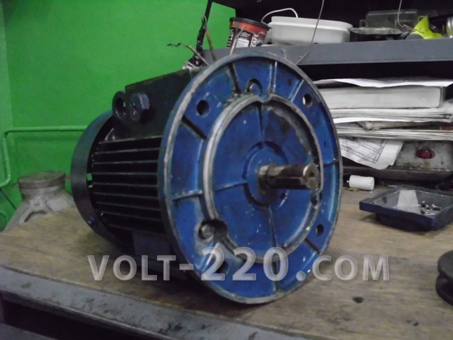
Engines come in the most different sizes. How larger sizes and mass, so more powerful engine. Whatever their size, they are all the same on the inside. A shaft with a key peeks out from the front side; on the other side, the rear is covered with an overlay plate-casing.

Usually terminal blocks are inserted into boxes on the engine. This allows for convenient installation, but due to many factors such pads are not available. Therefore, everything is done with reliable twisting.

The rating plate says about the engine power (0.75 kW), speed (1350 rpm), mains frequency (50 Hz), delta-star voltage (220/380), coefficient useful action(72%), power factor (0.75).
The winding resistance and motor current are not indicated here. The resistance is quite low when measured with an ohmmeter. An ohmmeter measures the active component, but does not touch the reactive component, i.e. inductance. When the motor is turned on, the rotor stands still and all the energy of the windings is closed on it. The current in this case exceeds the rated current by 3 - 7 times. Then the rotor begins to accelerate under the influence of a rotating magnetic field, the inductance increases, increases reactance and the current drops. The smaller the motor, the higher its active resistance (200 - 300 Ohms) and the more it is not afraid of phase failure. Large engines have small active resistance(2 - 10 Ohms) and phase loss is fatal for them.

The formula for calculating the motor current is as follows.

If you substitute the values for the motor being disassembled, you will get the following current value. It must be taken into account that the resulting current is the same in all three phases. Here power is expressed in kW (0.75), voltage in kV (0.38 V), efficiency and power factor - in fractions of unity. The resulting current is in amperes.

Engine disassembly begins by unscrewing the impeller casing. The casing is needed for the safety of personnel - to prevent hands from sticking into the impeller. There was a case when a labor safety engineer, showing students a turning shop, said “but you can’t do it like that,” stuck his finger into a hole in the casing and came across a rotating impeller. The finger was cut off, the student remembered the lesson well. All impellers are equipped with casings. In enterprises with a low level of profitability, the impeller is also removed along with the casing.
The impeller is fixed on the shaft with a mounting plate. In large engines the impeller is metal, in small engines it is plastic. To remove it, you need to bend the tendril of the plate and carefully pull it from both sides with screwdrivers and pull it off the shaft. If the impeller breaks, then you definitely need to install another one, because without it, the cooling of the engine will be disrupted, which will cause overheating and ultimately cause a breakdown of the engine insulation. The impeller is made from two strips of tin. The tin is bent in half rings around the rotor, tightened with two bolts and nuts so that it sits tightly on the shaft, and the free ends of the tin are bent. You will get an impeller with four blades - cheap and cheerful.


An important element is the key on the motor shaft. The key is used to vibrate the rotor in the landing sleeve or gear. The key prevents the rotor from turning relative to the seating element. Hammering a dowel is a delicate matter. Personally, I first push the gear onto the rotor a little, drive it 1/3 full, and only then insert the key and hammer it in a little. Then I fit the entire gear together with the key. With this method, the key will not come out the other way. Here it's all about cutting the groove for the key. On the side closest to the engine body, the groove for the key looks like a slide along which the key slides out very smoothly and easily. There are other types of grooves - closed with an oval key, but square keys are more common.

There are bolts on both sides of the covers. To further disassemble the engine, you need to unscrew them and put them in a jar so as not to lose them. These bolts secure the covers to the stator. The bearings fit tightly in the covers. After unscrewing all the bolts, the covers should come off, but they stick and fit very tightly. Do not use crowbars or screwdrivers to grab the ears to secure the casing and rip off the covers. Although the covers are made of duralumin or cast iron, they are very brittle. The easiest way is to hit the shaft through a bronze extension, or lift the engine and hit the shaft hard on a hard surface. The puller can also break the lids.

If the lids give way, everything is fine. One will work well, the other needs to be knocked out through the engine with a stick. The bearings must be knocked out with a stick from the back of the cover. If the bearing does not sit in the cover, but dangles, then you need to take a core and punch the entire bearing seating surface. Then fill the bearing. The bearing should not cause beating or creaking. When making repairs, it’s a good idea to open the closed bearings with a knife, remove the old grease and add new grease to 1/3 of the volume.

The stator of an AC induction motor is covered from the inside with windings. From the side of the key on the rotor, these windings are considered windings and this is in front of the engine. All ends of the coils come to the front windings and here the coils are collected in groups. To assemble the windings, you need to wind the coils, insert insulating spacers into the stator grooves, which will separate the steel stator from the insulated one. copper wire windings, lay the windings and cover the top with a second layer of insulation and fix the windings with insulating sticks, weld the ends of the windings, stretch the insulation over them, bring out the ends to connect the voltage, soak the entire stator in a bath of varnish and dry the stator in the oven.

The rotor of an asynchronous AC motor is short-circuited - there are no windings. Instead, a set of transformer steel round section with an asymmetrical shape. It can be seen that the grooves run in a spiral.

One of the methods for launching three phase motor line voltage from a two-wire phase voltage network is the inclusion of a working capacitor between the two phases. Unfortunately, the running capacitor cannot start the engine, you need to turn the motor by the shaft, but this is dangerous, but you can connect an additional starting capacitor in parallel with the running capacitor. With this approach, the engine will start. However, when the rated speed is reached, the starting capacitor must be disconnected, leaving only the working one.

The working capacitor is selected at the rate of 22 μF per 1 kW of motor. The starting capacitor is selected at the rate of 3 times larger than the working capacitor. If there is a 1.5 kW motor, then Cp = 1.5 * 22 = 33 µF; Sp = 3*33 = 99 uF. You only need a paper capacitor with a voltage of at least 160 V when the windings are connected in a star and 250 V when the windings are connected in a delta. It is worth noting that it is better to use the connection of the windings in a star - more power.
The Chinese do not face the problem of certification or registration, so all innovations from the magazines “Radio” and “Modelist Kstruktor” are made instantly. For example, here is a three-phase motor that can be turned on at 220 V and in automatic mode. For this purpose, a horseshoe-shaped plate with a normally closed contact is located next to the front windings.

IN distribution box Instead of the terminal block, capacitors are inserted. One at 16 uF 450 V is working, the second at 50 uF 250 V is starting. Why there is such a difference in voltage is unclear, apparently they shoved what was there.

On the engine rotor there is a spring-loaded piece of plastic, which, under the influence of centrifugal force, presses on the horseshoe-shaped contact and opens the starting capacitor circuit.
It turns out that when the engine is turned on, both capacitors are connected. The rotor spins up to certain speeds, at which the Chinese consider that the start is complete, the plate on the rotor moves, pressing on the contact and turning off the starting capacitor. If you leave the start capacitor connected, the motor will overheat.

To start the engine from a 380 V system, you need to disconnect the capacitors, ring the windings and connect the voltage three-phase network to them.

Good luck everyone.
Design of three-phase asynchronous motors (stator and rotor of asynchronous motors)
A three-phase asynchronous motor consists of a stationary stator and rotor. Three windings are placed in slots on inside stator core of an asynchronous motor. The rotor winding of an asynchronous motor does not have electrical connection with network and stator winding. The beginning and ends of the phases of the stator windings are connected to the terminals in the terminal box according to a star or delta circuit.
Asynchronous motors mainly differ in the design of the rotor, which is of two types: phase or squirrel-cage. The winding of the squirrel cage rotor of an asynchronous motor is made on a cylinder of copper rods and is called a “squirrel cage”. The end ends of the rods close metal rings. The rotor package is made of electrical steel. In lower power engines, the rods are filled with aluminum. The wound rotor and stator have three-phase winding. The phases of the winding are connected in a star or triangle and its free ends are led out to insulated slip rings.
Obtaining a rotating magnetic fieldThe stator winding of an asynchronous motor in the form of three coils is laid in grooves located at an angle of 120 degrees. The beginning and end of the coils are designated by the letters A, B, C and X,Y,Z, respectively. When fed to reels three-phase voltage currents Ia, Ib, Ic will be established in them and the coils will create their own alternating magnetic field. The current in any coil is positive when it is directed from the beginning to its end and negative when it is directed in the opposite direction. The vectors of the magnetizing force coincide with the axes of the coils, and their magnitude is determined by the values of the currents; the direction of the resulting vector coincides with the axis of the coil. The vector of the resulting magnetizing force rotates 120 degrees while maintaining the value coincides with the axis of the corresponding coil. Thus, over a period, the resulting magnetic field of the stator rotates at a constant speed. The operation of a three-phase asynchronous motor is based on the interaction of a rotating magnetic field with currents induced in the rotor conductors.
Operating principle of a three-phase asynchronous motorThe set of moments created by individual conductors forms the resulting torque of the motor; an electromagnetic pair of forces arises, which tends to turn the rotor in the direction of movement of the electromagnetic field of the stator. The rotor begins to rotate and acquires a certain speed, the magnetic field and the rotor rotate with at different speeds or asynchronously. In relation to asynchronous motors, the rotor speed is always less speed rotation of the stator magnetic field.

In asynchronous motors with a large moment of inertia, it is necessary to increase the torque while simultaneously limiting the starting currents - motors with wound rotors are used for these purposes. To increase the initial starting torque A three-phase rheostat is included in the rotor circuit. At the beginning of the start, it is fully introduced, and the starting current decreases. During operation, the rheostat is completely withdrawn. To start asynchronous motors with a squirrel-cage rotor, three schemes are used: with a reluctance coil, with an autotransformer and with switching from star to delta. The switch connects the reluctance coil and the motor stator in series. When the rotor speed approaches the nominal speed, the switch closes, it short-circuits the coil and the stator switches to full mains voltage. During autotransformer starting, as the engine accelerates, the autotransformer is transferred to working position, in which the stator is supplied with full mains voltage. Starting an asynchronous motor with pre-switching on winding the stator with a star and then switching it to a triangle gives a threefold reduction in current.
Changing the rotor speed of a three-phase asynchronous motorThe parallel windings of two phases form one pair of poles shifted in space by 120 degrees. Serial connection The windings form two pairs of poles, which makes it possible to reduce the rotation speed by half. To regulate the rotor rotation speed by changing the current frequency, a separate current source or an energy converter with adjustable frequency made on thyristors is used.
Engine braking methodsWhen braking by back-switching, the two wires connecting the three-phase network to the stator windings change, thereby changing the direction of movement of the machine's magnetic field. In this case, the regime begins electromagnetic brake. For dynamic braking, the stator winding is disconnected from the three-phase network and connected to the DC network. The stationary stator field causes the rotor to stop quickly. Asynchronous motors are widely used in industry. IN construction mechanisms, on metalworking machines, in forging and pressing equipment, in power drives of rolling mills, in radar stations and many other industries.
|
|
We supply 3-phase and single-phase NORD AC asynchronous electric motors in Moscow. A large number of options: low noise level, ease of maintenance and high reliability are the main advantages of NORD engines. IN Lately began to gain great popularity asynchronous electric motor alternating current. NORD company produces only single-phase and 3-phase asynchronous electric motors phase current. We supply single-phase and 3-phase nord motors with moisture protection, motors with dust protection, including ip55 motors, nord 50Hz and 60Hz electric motors. Our specialists will help you replace three-phase motors from other manufacturers with an SK electric motor. NORD produces asynchronous three-phase motors in the following sizes: electric motor SK63S/4 to electric motor SK315MA/4. NORD asynchronous 3-phase motors according to their purpose are divided into: |

NORD supplies electric motors in the following versions:
- explosion-proof with ignition protection type “e”
- explosion-proof with ignition protection type “de“
- explosion-proof with ignition protection type “n”
- with protection against explosive dust
- single-phase asynchronous electric motor with working and starting capacitor
- single-phase asynchronous electric motor with working capacitor
- single-phase asynchronous electric motor with a working capacitor and connection according to the Steinmetz circuit
- according to EPACT
- compliant with US-Canadian standard
- compliant with CUS (American-Canadian standard)
Asynchronous 3 phase motor superior to DC motors in many respects: it is simple in design and reliable, has a lower cost, is easy to manufacture and operate. The main disadvantage of asynchronous electric motors is the difficulty of regulating their speed. Frequency regulation asynchronous electric motor relatively recently was considered big problem. Variable frequency drive development has been held back high cost frequency regulators. But the development of high-performance systems has helped reduce the cost of modern frequency controllers. 3-phase NORD motors allow operation in short-term, intermittent, long-term and continuous modes with intermittent load. The basic version is manufactured in an IP55 housing. The leroy somer engine and the lenze engine can be replaced with NORD engines. When manufacturing and selecting a nord electric motor great importance have operating conditions and climatic conditions. Nord engines are often used with frequency converter or are part of . Now you can buy an asynchronous electric motor in Moscow, please contact our managers.
Those that convert alternating current electrical energy into mechanical energy are called AC electric motors.
In industry, the most widely used asynchronous motors three-phase current. Let's consider the design and principle of operation of these engines.
The operating principle of an asynchronous motor is based on the use of a rotating magnetic field.
To understand the operation of such an engine, let us perform the following experiment.
Let's fix it on the axis so that it can be rotated by the handle. Between the poles of the magnet we will place a copper cylinder on an axis that can rotate freely.
Picture 1. The simplest model to obtain a rotating magnetic field
Let's start rotating the magnet by the handle clockwise. The magnet field will also begin to rotate and, as it rotates, will intersect the copper cylinder with its lines of force. In the cylinder, there will appear, which will create their own - the field of the cylinder. This field will interact with the magnetic field permanent magnet, as a result of which the cylinder will begin to rotate in the same direction as the magnet.
It has been established that the rotation speed of the cylinder is somewhat less than the rotation speed of the magnet field.
Indeed, if the cylinder rotates at the same speed as the magnetic field, then the magnetic lines of force do not cross it, and therefore, eddy currents do not arise in it, causing the rotation of the cylinder.
The rotation speed of the magnetic field is usually called synchronous, since it is equal to the rotation speed of the magnet, and the rotation speed of the cylinder is asynchronous (non-synchronous). That's why the engine itself got the name asynchronous motor. The rotation speed of the cylinder (rotor) differs from the synchronous rotation speed of the magnetic field by a small amount called slip.
Denoting the rotor rotation speed as n1 and the field rotation speed as n, we can calculate slip amount as a percentage according to the formula:
s = (n - n1) / n.
In the above experiment, we obtained a rotating magnetic field and the rotation of the cylinder caused by it due to the rotation of a permanent magnet, therefore such a device is not yet electric motor. It is necessary to force the creation of a rotating magnetic field and use it to rotate the rotor. This problem was brilliantly solved by M. O. Dolivo-Dobrovolsky in his time. He proposed using three-phase current for this purpose.
Design of an asynchronous electric motor by M. O. Dolivo-Dobrovolsky

Figure 2. Diagram of the Dolivo-Dobrovolsky asynchronous electric motor
At the poles of a ring-shaped iron core called electric motor stator, three windings are placed, three-phase current networks 0 located one relative to the other at an angle of 120°.
Inside the core, a metal cylinder called electric motor rotor.
If the windings are connected to each other as shown in the figure and connected to a three-phase current network, then the total magnetic flux created by the three poles will turn out to be rotating.
Figure 3 shows a graph of changes in currents in the motor windings and the process of occurrence of a rotating magnetic field.
Let's take a closer look at this process.

Figure 3. Obtaining a rotating magnetic field
In position “A” on the graph, the current in the first phase is zero, in the second phase it is negative, and in the third it is positive. The current through the pole coils will flow in the direction indicated by the arrows in the figure.
Determined by the rule right hand direction of the magnetic flux created by the current, we will make sure that a south pole (S) will be created at the inner end of the pole (facing the rotor) of the third coil, and a north pole (C) will be created at the pole of the second coil. The total magnetic flux will be directed from the pole of the second coil through the rotor to the pole of the third coil.
 In position “B” on the graph, the current in the second phase is zero, in the first phase it is positive, and in the third phase it is negative. The current flowing through the pole coils creates a south pole (S) at the end of the first coil, and a north pole (C) at the end of the third coil. The total magnetic flux will now be directed from the third pole through the rotor to the first pole, i.e. the poles will move 120°.
In position “B” on the graph, the current in the third phase is zero, in the second phase it is positive, and in the first phase it is negative. Now the current flowing through the first and second coils will create a north pole (C) at the end of the pole of the first coil, and a south pole (S) at the end of the pole of the second coil, i.e. the polarity of the total magnetic field will move another 120°. At position “G” on the graph, the magnetic field will move another 120°.
Thus, the total magnetic flux will change its direction with a change in the direction of the current in the stator windings (poles).
In this case, during one period of change in the current in the windings, the magnetic flux will make a full revolution. The rotating magnetic flux will carry the cylinder along with it, and thus we will get an asynchronous electric motor.
Let us recall that in Figure 3 the stator windings are connected by a “star”, however, a rotating magnetic field is also formed when they are connected by a “triangle”.
If we swap the windings of the second and third phases, then the magnetic flux will change the direction of its rotation to the opposite.
The same result can be achieved without swapping the stator windings, but by directing the current of the second phase of the network to the third phase of the stator, and the third phase of the network to the second phase of the stator.
Thus, You can change the direction of rotation of the magnetic field by switching any two phases.
We have reviewed device of an asynchronous motor with three windings on the stator. In this case, the rotating magnetic field is bipolar and the number of its revolutions per second is equal to the number of periods of current change per second.
 If six windings are placed around a circle on the stator, it will be created four-pole rotating magnetic field. With nine windings the field will be six-pole.
With a three-phase current frequency f equal to 50 cycles per second, or 3000 per minute, the number of revolutions n of the rotating field per minute will be:
with a two-pole stator n = (50 x 60) / 1 = 3000 rpm,
with a four-pole stator n = (50 x 60) / 2 = 1500 rpm,
with a six-pole stator n = (50 x 60) / 3 = 1000 rpm,
with the number of stator pole pairs equal to p: n = (f x 60) / p,
So, we have established the rotation speed of the magnetic field and its dependence on the number of windings on the motor stator.
The engine rotor will, as we know, lag somewhat behind in its rotation.
However, the rotor lag is very small. So, for example, when the engine is idling, the speed difference is only 3%, and when the load is 5 - 7%. Consequently, the speed of an asynchronous motor changes within very small limits when the load changes, which is one of its advantages.

Let us now consider the design of asynchronous electric motors


Asynchronous electric motor disassembled: a) stator; b) rotor in squirrel-cage design; c) rotor in phase design (1 - frame; 2 - core made of stamped steel sheets; 3 - winding; 4 - shaft; 5 - slip rings)
Stator of a modern asynchronous electric motor has unexpressed poles, i.e. inner surface The stator is made completely smooth.
To reduce eddy current losses, the stator core is made of thin stamped steel sheets.  The assembled stator core is secured in a steel housing.
A winding of copper wire is placed in the stator slots. The phase windings of the stator of the electric motor are connected by a “star” or “delta”, for which all the beginnings and ends of the windings are brought out to the housing - to a special insulating shield. This stator device is very convenient, as it allows you to switch its windings to different standard voltages.
Asynchronous motor rotor, like the stator, is assembled from stamped steel sheets. The winding is placed in the slots of the rotor.
Depending on the rotor design, asynchronous electric motors are divided into motors with squirrel-cage rotor and wound rotor.
The winding of the squirrel-cage rotor is made of copper rods placed in the grooves of the rotor. The ends of the rods are connected using a copper ring. This type of winding is called a squirrel cage winding. Note that the copper rods in the grooves are not insulated.
In some engines, the squirrel cage is replaced with a cast rotor.

(with slip rings) is usually used in high power electric motors and in those cases; when it is necessary for the electric motor to create a large force when starting off. This is achieved by turning on the winding of the phase motor.
Squirrel-cage asynchronous motors are driven in two ways:
1) Direct connection of three-phase mains voltage to the motor stator. This method is the simplest and most popular.
2) By reducing the voltage supplied to the stator windings. The voltage is reduced, for example, by switching the stator windings from star to delta.
The engine is started when the stator windings are connected in a star, and when the rotor reaches the normal speed, the stator windings switch to a delta connection.
The current in the supply wires with this method of starting the engine is reduced by 3 times compared to the current that would arise when starting the engine by direct connection to the network with the stator windings connected by a delta. However, this method is only suitable if the stator is designed for normal operation when connecting its windings with a “triangle”.
The simplest, cheapest and most reliable is asynchronous electric motor with squirrel-cage rotor, but this engine has some disadvantages - low starting force and high starting current. These disadvantages are largely eliminated by the use of a wound rotor, but the use of such a rotor significantly increases the cost of the engine and requires a starting rheostat.

Types of asynchronous electric motors
Basic type asynchronous machines - three phase asynchronous motor. It has three windings on the stator, displaced in space by 120°. The windings are connected in star or delta and are supplied with three-phase alternating current.
Engines low power in most cases they are performed as two-phase. Unlike three-phase motors they have two windings on the stator, the currents in which must be shifted by an angle π /2 to create a rotating magnetic field.
If the currents in the windings are equal in magnitude and shifted in phase by 90°, then the operation of such a motor will be no different from the operation of a three-phase one. However, such motors with two windings on the stator are in most cases powered by single-phase network and a shift approaching 90° is created artificially, usually by capacitors.
Single phase motor, having only one winding on the stator, is practically inoperable. When the rotor is stationary, only a pulsating magnetic field is created in the motor and the torque is zero. True, if the rotor of such a machine is spun to a certain speed, then it can then perform the functions of an engine.
In this case, although there will only be a pulsating field, it is composed of two symmetrical ones - direct and reverse, which create unequal torques - a larger motor and a smaller braking one, arising due to rotor currents of high frequency (slip relative to the inversely synchronous field is greater than 1).
In connection with the above single phase motors are equipped with a second winding, which is used as a starting winding. To create a phase shift of the current, capacitors are included in the circuit of this winding, the capacitance of which can be quite large (tens of microfarads with an engine power of less than 1 kW).
Control systems use two phase motors which are sometimes called executive. They have two windings on the stator, shifted in space by 90°. One of the windings, called the field winding, is directly connected to the 50 or 400 Hz network. The second is used as a control winding.
To create a rotating magnetic field and the corresponding torque, the current in the control winding must be shifted by an angle close to 90°. Motor speed control, as will be shown below, is carried out by changing the value or phase of the current in this winding. Reversal is ensured by changing the phase of the current in the control winding by 180° (switching the winding).
Two-phase motors are manufactured in several versions:
with squirrel-cage rotor,
with a hollow non-magnetic rotor,
with a hollow magnetic rotor.
Linear motors
Converting the rotational movement of the engine into the translational movement of organs working machine always associated with the need to use any mechanical components: racks, propeller, etc. Therefore, sometimes it is advisable to design an engine with linear movement of a rotor-runner (the name “rotor” can only be accepted conditionally - as a moving organ).
In this case, the engine is said to be able to be deployed. Stator winding linear motor is performed in the same way as for a displacement engine, but must only be inserted into the grooves for the entire length of the maximum possible movement of the runner rotor. The runner rotor is usually short-circuited; the working body of the mechanism is articulated with it. At the ends of the stator, naturally, there must be limiters that prevent the rotor from leaving the working limits of the path.
 (1 ratings, on average: 5,00 out of 5)

