Asynchronous motor operating principle. Two-phase electrical network
If you provide the motor stator with only one single-phase winding(Fig. 14.33), then the alternating current in it will excite in the machine, while its rotor is stationary, an alternating magnetic field, the axis of which is also stationary. This field will induce an EMF in the rotor winding, under the influence of which currents will arise in it. Interaction of rotor currents with magnetic field stator will create electromagnetic forces f, oppositely directed in the right and left halves of the rotor. As a result, the resulting torque acting on the rotor will be equal to zero. Consequently, if there is one winding, the initial starting torque of a single-phase motor is zero, i.e., such a motor cannot start on its own.
Two methods are used to create an initial starting torque in motors connected to one phase of the network, according to which these motors are divided into two-phase and single-phase.
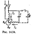
Two-phase asynchronous motors . Two-phase motors, in addition to the winding connected directly to the mains voltage, are equipped with a second winding connected in series with one or another phase-shifting device (capacitor, inductor). The most advantageous of these is the capacitor (Fig. 14.34), and the corresponding motors are called capacitor. In the stator slots of such motors there are two phase windings, each of which occupies half of all slots. In this way, the condition for obtaining torque through an induction mechanism is fulfilled (see § 12.9): the presence of two variable magnetic fluxes, displaced in space and out of phase relative to each other.
The most advantageous is a circular rotating magnetic field. It can be implemented in a two-phase motor. In this case, however, it is necessary to choose the conditions under which it is preferable to obtain a circular field, and therefore the greatest torque - when the engine is running or at rated load.
Indeed, if the currents in the stator windings 1 and 2 have equal effective values and are shifted relative to each other in phase by an angle /2, then the magnetic field excited by them has the components B x And In y, defined by expressions (14.2) and (14.3). The resulting magnetic field in this case is a circular rotating field.
If the capacitance of the capacitor is selected in such a way that a circular magnetic field is created when starting the engine, then at rated load, a change in the current of the second winding will cause a change in the voltage drop across the capacitor, and, consequently, the voltage on the second winding in value and phase. As a result, the rotating magnetic field will become elliptical (the flow will pulsate during rotation), which will cause a decrease in torque.
At the cost of complicating the installation - by disconnecting some of the capacitors during the transition from starting conditions to operating conditions (dash-dotted connections in Fig. 14.34) this drawback can be eliminated. This reduction in capacitor capacity can be performed automatically by a centrifugal switch, which is triggered when the engine speed reaches 75-80% of the rated speed, or by the action of a time relay.
 Two-phase motors are also used in automatic devices as controlled motors: their rotation speed or torque is controlled by changing effective value or voltage phase on one of the windings. Such motors, instead of a conventional squirrel-cage rotor, are equipped with a rotor in the form of a hollow thin-walled aluminum cylinder (“cup”) rotating in a narrow air gap between the stator and a stationary central sheet steel core (inner stator). This hollow rotor motors have negligible inertia, which is practically very important when regulating certain production processes. In Fig. Figure 14.35 shows a graph of the rotation speed of such a motor depending on the voltage on the control winding.
Single-phase asynchronous motors do not develop initial starting torque. But if the rotor single phase motor spin in any direction using an external force, then in the future this rotor will rotate independently and can develop significant torque.

Similar conditions are created for a three-phase motor when a fuse blows in one of the phases. Under such single-phase power conditions, the three-phase motor will continue to operate. Only to avoid overheating of the two windings that remain switched on, it is necessary that the motor load does not exceed 50-60% of the rated one.
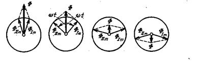
The operation of a single-phase motor can be explained on the basis that an alternating magnetic field can be considered as the result of the superposition of two magnetic fields rotating in opposite directions at a constant angular velocity /R. Amplitude values of magnetic fluxes of these fields F 1t And F IIm are identical and equal to half the amplitude of the magnetic flux of the alternating field of the machine:
F 1t=F IIm = F m/2
A simple graphical construction (Fig. 14.36) shows how, as a result of the addition of two identical magnetic fluxes Ф 1 m and Ф II t, rotating in opposite directions, a magnetic flux is obtained that varies according to a sinusoidal law: Ф = Ф t sin t.
In a single-phase motor, this position is valid only while the rotor is stationary. Considering under these conditions the alternating field as the sum of two rotating fields, we can conclude that under the influence of both these fields there will be equal currents in the rotor winding. The rotor currents, interacting with the rotating fields, create two identical rotating moments, directed in opposite directions and balancing each other.
This equality of two moments is violated if the rotor is rotated in any direction. Under these conditions, the torque created by a directly rotating field (in short, a direct field), i.e., a field rotating in the same direction as the rotor, becomes significantly greater than the torque developed by a reverse rotating field (in short, a reverse field), thanks to whereby the rotor can not only rotate independently, but also cause any mechanism to rotate.
The weakening of the counteracting torque when the rotor rotates is caused by a weakening of the reverse field. Relative to this field rotating against the direction of rotation of the rotor, the rotor slip is equal to:
s II = = = 2-s 1
where s I is the rotor slip relative to the direct field.
Expression (14.36) shows that the frequency of currents induced in the rotor by the reverse field is relatively high - close to twice the network frequency. For currents of such high frequency, the inductive reactance of the rotor is many times greater than it active resistance, as a result of which the currents induced by the reverse field become almost purely reactive. According to Fig. 14.21 the field of these currents has a strong demagnetizing effect on the field, which inactivates them, therefore, on the reverse field of the motor. Thanks to this, with small slips s l the resulting magnetic field of the machine becomes an almost circular rotating field, and the counteracting torque of the reverse field is small under these conditions.
 Rice. 14.36.
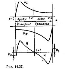 For each of the fields, we can apply the torque versus slip curves known to us for a conventional three-phase asynchronous motor and determine the resulting torque M as the difference between the direct M I and reverse M II moments (Fig. 14.37). An essential feature of a single-phase motor is the presence of a small negative torque M 0 at synchronous rotor speed with respect to the direct field.
An increase in slip s I, with an increase in load, causes in a single-phase motor not only an increase in the current I 1 induced by the direct field, but also an increase in the braking torque of the reverse field, as a result of which the operation of a single-phase motor is much less stable than a three-phase one
phase, and its maximum torque is significantly less. Due to a number of additional losses, the efficiency of a single-phase motor is significantly lower than that of a three-phase motor.
The task of starting a single-phase motor is solved by using one or another starting device. Most often this additional winding, similar to the second winding two phase motor, but switched off at the end of the start, since it is calculated only for a short-term current load. One or another phase-shifting device is connected in series with this winding.
Shaded Pole Induction Motors. The starting device in a single-phase asynchronous motor can remain switched on during normal operation of the motor. This occurs in shaded pole induction motors. Such motors can be considered as intermediate between single-phase and two-phase asynchronous motors (Fig. 14.38). This motor is equipped with a short-circuited winding, which covers part of the salient pole on which the main (primary) winding is located. 1 . Current I 1 in the winding 1 , connected to the network, excites magnetic flux F 1. Part of the latter, threading the winding wK, induces a current I 2 in it, significantly lagging in phase from I 1. This current excites the second magnetic flux of the motor. Thus, a system of two alternating magnetic fluxes is created in the engine, not combined spatially and shifted in phase, i.e., conditions similar to those in induction electrical measuring instruments are created (see Fig. 12.23), therefore, a rotating magnetic field arises, which, acting on the squirrel-cage rotor 2, creates the corresponding torque. These motors are manufactured miniature (power 0.5-30 W) and are widely used for a variety of purposes - mainly as a drive for actuators.
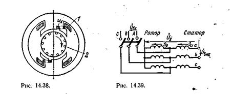
In automation systems, a system is often used to power executive asynchronous micromotors two-phase current. It is convenient to obtain two-phase current from three-phase current by using special transformer circuits. The most widely used circuit is one consisting of two unequal single-phase transformers. I And II(Fig. 1.5 A). In this circuit, point 0 divides the turns of the primary winding of the transformer II into two equal parts. Transformer winding voltages I And II shifted by a quarter period. Transformer primary voltages I And II or (Fig. 1.5, b).
To obtain equal voltages on the secondary windings of transformers, it is necessary that the transformation ratio of the transformer I was times larger than the transformer II. Typically both transformers are made with the same number secondary turns, but the primary turns of the transformer I have a branch at a distance of a number of turns from the beginning of the winding. With symmetrical two-phase currents in the secondary circuit, the currents in the three-phase primary circuit are also symmetrical.
Rice. 1.5. Converting three-phase current to two-phase:
A– transformer circuit; b – vector diagram stress
primary windings
1.3.2. Three-phase power converter
in six- and twelve-phase
In some cases, it is necessary to convert three-phase current into six- and twelve-phase. To convert to six-phase current, a three-rod transformer is used, on each rod of which one phase of the primary winding and two identical phases of the secondary winding are placed. The secondary windings can be connected in two stars (Fig. 1.6), in a closed polygon or in a zigzag.
Rice. 1.6. Converting a three-phase current system to a six-phase one:
A– connection diagram of the transformer windings;
b– vector diagram of the EMF of the primary winding;
V– vector diagram of the EMF of the secondary winding

To convert to twelve-phase current, the secondary windings are connected in a double zigzag (Fig. 1.7). In this case, the number of turns in the branch of the six-phase part should be 2.75 times greater than in the twelve-phase part. In the case of a symmetrical load, the current in a six-phase zone is 1.93 times greater than in a twelve-phase zone. Twelve-phase current can also be obtained using two transformers three-phase current, converting to six-phase, one of which has a primary winding connected by a star, and the other by a delta.
Nail extensions are extremely popular in the modern fashion industry. This allows girls not to be afraid of broken nails and to calmly carry out any homework. At the same time, there is no need to constantly cover your own nails with varnish, which wears off very quickly when active work hands. The nail plate of natural nails does not get wet, does not flake, and does not require constant moisturizing and care with oils and medicated varnishes. Nails do not absorb harmful substances, as when varnished, and also do not turn yellow, as happens when using brightly colored varnishes.
The extension procedure allows the master to create perfect shape and length of nails, strengthen the natural nail plate, restore a broken nail. Under a layer of hard coating, your own nails grow very quickly and are not subject to mechanical and chemical exposure from outside.
How does the nail extension procedure work?
There are several nail extension techniques. This applies to both the materials used and the methods of their application. For example, some masters still use nail extensions using tips - when a plastic overlay is glued to a natural nail, on top of which a builder gel is applied. in most cases, masters have already moved away from this method, since it can seriously injure the nail plate. But nevertheless, you have to resort to extensions using tips in cases where your own nail does not have a free edge, that is, it is too short, or has irregular shape(deformed, broken). 
The most common extension technique is extensions on forms. With this method, a rigid form is placed under the natural nail, on top of which a gel is applied, which, when hardened, forms the shape of an artificial nail.
Typically, growth occurs in several stages:
- Manicure and nail preparation. At this stage, the master removes the cuticle, hangnails, pterygium, trims the shape of the natural nail, and shortens its length, if necessary. Then the master removes the glossy film of the natural nail with a soft file to ensure maximum adhesion of the gel coating to the natural nail.
- Degreasing. At this stage, the surface of each nail is treated with a special degreasing agent (sometimes nail polish remover or alcohol is used). Then the nail is treated with a primer (primer) to hold the gel on the nail plate.
- Direct extension.
Types of gel
Different hairdressers are accustomed to different extension techniques. Some people prefer using a single-phase gel, while others are used to a three-phase system. What are they?
is a method in which the formation of an artificial nail occurs using one substance. It is at the same time a base, a builder gel, and a top coat for itself. This is convenient for the manicurist and allows you to spend less time on such a lengthy procedure as nail extensions. 
is a system in which the formation of an artificial nail takes place in three stages: application of a base gel, application of a constructor gel and application of a top gel. 
Pros and cons of single-phase and three-phase systems
A single-phase system has advantages less labor and material costs. This method of extension is convenient for beginners and makes the cost of the services provided more affordable for everyone. large quantity clients. But meanwhile, such a system does not guarantee long-term wear of nails. This is due to the fact that with single-phase extensions, as a rule, the use of a primer is not provided, which means that the clutch artificial turf with a natural nail plate it will be a little weaker.
Also, the coating can be poorly dried due to one, but sufficiently thick layer. This option is suitable if there is no need to wear nails for a long time, and they are done for a one-time appearance: to a wedding, party, performance, competition. 
The three-phase system is most in demand among professional craftsmen. The use of several types of materials, each of which performs its own function, increases the wear time of the artificial turf and provides a greater guarantee. For the master, as well as for the client, this technique requires large material costs. This procedure takes more time than single-phase extension. Under base layer a primer is used, this improves the adhesion between the gel and the nail. After the base layer has dried, a builder gel is applied. it is applied in such a layer that in the stress zone (the end zone of the natural nail) the thickness of the gel is sufficient to protect it from breaking.
After this, the master applies colored gel to the artificial nail. The extension is completed by applying a finishing layer, which provides a mirror-like shine to the nails and maximally secures all previous layers.
Nail extension both with a single-phase system and with a three-phase system should be carried out qualified specialist taking into account compliance with the extension technique. The client has the right to ask the master to extend his nails either using a single-phase gel or using a base and top coat. Consumables must be of high quality and fresh, then the risk of chipping and swelling of the artificial turf is almost eliminated.
Two-phase electrical networks used at the beginning of the 20th century in electrical distribution networks alternating current. They used two circuits, the voltages in which were phase-shifted relative to each other at or 90 degrees. Typically, four lines were used in the circuits - two for each phase. One was used less frequently common wire, which had a larger diameter than the other two wires. Some of the earliest two-phase generators each had two full-fledged rotors with windings physically rotated 90 degrees.
For the first time, the idea of using two-phase current to create torque were expressed Dominic Arago V 1827 . Practical use was described Nikola Tesla in his patents from 1888, around the same time he developed a design two-phase electric motor. These patents were then sold to the company Westinghouse, which began to develop two-phase networks with the USA. Later, these networks were supplanted by three-phase networks, the theory of which was developed by a Russian engineer Mikhail Osipovich Dolivo-Dobrovolsky, who worked in Germany in the company AEG. However, due to the fact that Tesla's patents contained general ideas use of polyphase circuits, the Westinghouse company was able to hold back their development for some time through patent litigation.
The advantage of two-phase networks was that they allowed simple, soft starting of electric motors. In the early days of electrical engineering, these networks with two separate phases were easier to analyze and design. Wasn't created yet method of symmetrical components(it was invented in 1918), which subsequently gave engineers convenient mathematical tools for analyzing asymmetric load conditions of multiphase electrical systems.
Two-phase circuits typically use two separate pairs of current-carrying conductors. Three conductors can be used, however, the vector sum of phase currents flows through the common wire, and therefore the common wire must have a larger diameter. In contrast to this, in three-phase networks with a symmetrical load, the vector sum of the phase currents is zero, and therefore in these networks it is possible to use three lines of the same diameter. For electrical distribution networks, the requirement of three conductor lines is better than the requirement of four, since this results in significant savings in the cost of conductor lines and in installation costs.
Two-phase voltage can be obtained from a three-phase source by connecting single-phase transformers according to the so-called Scott circuit. Symmetrical load in such three-phase system exactly equivalent to a symmetrical three-phase load.
Encyclopedic YouTube
1 / 3
Science 2.0 Energy. Electricity of the net
Electrical engineering. Three-phase circuits part 1
Connection three phase motor To single-phase network (220)
Subtitles
Two-phase electric current
Two-phase electric shock is a set of two single-phase currents shifted in phase relative to each other by an angle π 2 (\displaystyle (\frac (\pi )(2))), or 90°:
I 1 = I m sin ω t (\displaystyle i_(1)=I_(m)\sin \omega t);
I 2 = I m sin (ω t − π 2) (\displaystyle i_(2)=I_(m)\sin(\omega t-(\frac (\pi )(2)))).
Φ 1 = Φ m sin ω t (\displaystyle \Phi _(1)=\Phi _(m)\sin \omega t);
Φ 2 = Φ m sin (ω t − π 2) (\displaystyle \Phi _(2)=\Phi _(m)\sin(\omega t-(\frac (\pi )(2)))).
Since the magnetic fluxes are spatially located at an angle of 90° to each other, the resulting magnetic flux will be equal to their geometric sum:
Φ 0 = Φ m sin (ω t) 2 + Φ m sin (ω t − π 2) 2 (\displaystyle \Phi _(0)=(\sqrt (\Phi _(m)\sin(\omega t)^(2)+\Phi _(m)\sin(\omega t-(\frac (\pi )(2)))^(2)))).
But Φ m sin (ω t − π 2) = − Φ m cos ω t (\displaystyle \Phi _(m)\sin(\omega t-(\frac (\pi )(2)))=-\ Phi_(m)\cos\omega t), That's why Φ 0 = Φ m sin (ω t) 2 + (− Φ m sin (ω t − π 2) 2) (\displaystyle \Phi _(0)=(\sqrt (\Phi _(m)\sin (\omega t)^(2)+(-\Phi _(m)\sin(\omega t-(\frac (\pi )(2)))^(2))))), or Φ 0 = Φ m (\displaystyle \Phi _(0)=\Phi _(m))
 (1 ratings, on average: 5,00 out of 5)

