How to connect a three-phase motor to a household network. Three-phase motor - to a single-phase network
The function of stabilizers is that they act as capacitive energy fillers for stabilizer filter rectifiers. They can also transmit a signal between amplifiers. Capacitors are also used in an AC system for induction motors to start and run for an extended amount of time. The operating time of such a system can be varied using the capacitance of the selected capacitor.
The first and only main parameter of the above tool is capacity. It depends on the area of the active connection, which is insulated with a dielectric layer. This layer is practically invisible to the human eye, a small number of atomic layers form the width of the film.
The electrolyte is used if it is necessary to restore the layer of the oxide film. For correct operation device, it is necessary that the system be connected to a network with alternating current of 220 V and have a clearly defined polarity.
That is, the capacitor was created in order to accumulate, store and transmit a certain amount of energy. So why are they needed if you can connect the power source directly to the engine. Everything here is not so simple. If you connect the engine directly to a power source, then at best it will not work, at worst it will burn out.
In order to three-phase motor worked in a single-phase circuit, you need an apparatus that can shift the phase by 90 ° on the working (third) output. The capacitor also plays a role, such as an inductor, due to the fact that alternating current- its jumps are leveled due to the fact that, before work, in the capacitor, negative and positive charges are evenly accumulated on the plates, and then transferred to the receiving device.
There are 3 main types of capacitors:
- Electrolytic;
- non-polar;
- Polar.
Description of types of capacitors and calculation of specific capacitance

When choosing the best option, you need to consider several factors. If the connection is made through a single-phase network with a voltage of 220 V, then a phase-shifting mechanism must be used to start. Moreover, there should be two of them, not only for the capacitor itself, but also for the engine. Formulas used to calculate specific capacity capacitor, depends on the type of connection to the system, there are only two of them: a triangle and a star.
I 1 - rated current of the motor phase, A (Amperes, most often indicated on the motor packaging);
U network - voltage in the network (the most standard options are 220 and 380 V). There are also higher voltages, but they require completely different types of connections and more powerful motors.
Sp = Cp + Co
where Sp is the starting capacity, Cp is working capacity, Co - switchable capacitance.
In order not to strain with the calculations smart people brought out the average optimal values, knowing the optimal power of electric motors, which is designated - M. An important rule is that the starting capacity must be greater than the working one.
At power From 0.4 to 0.8 kW: working capacitance - 40 microfarads, starting power - 80 microfarads, From 0.8 to 1.1 kW: 80 microfarads and 160 microfarads, respectively. From 1.1 to 1.5 kW: Cp - 100 uF, Sp - 200 uF. From 1.5-2.2 kW: Cp - 150 uF, Sp 250 uF; At 2.2 kW, the operating power must be at least 230 microfarads, and the starting power should be 300 microfarads.
When connecting a motor designed to operate at 380 V to an AC network with a voltage of 220 V, there is a loss of half of the rated power, although this does not affect the speed of rotation of the rotor. When calculating power, this is an important factor, these losses can be reduced with a “triangle” connection scheme, Engine efficiency in this case it will be equal to 70%.
It is better not to use polar capacitors in a system connected to an alternating current network, in this case the dielectric layer is destroyed and the device heats up and, as a result, short-circuits
Connection diagram "Triangle"
The connection itself is relatively easy, connecting a conductive wire to and from the motor (or motor) terminals. That is, if we take it more simply, there is a motor in it there are three conductive ones. 1 - zero, 2 - working, 3 - phase.
The power wire is lit and it has two main wires in a blue and brown winding, the brown one is connected to terminal 1, one of the capacitor wires is also connected to it, the second wire of the capacitor is connected to the second working terminal, and the blue power wire is connected to the phase.
If the motor power is small, up to one and a half kW, in principle only one capacitor can be used. But when working with loads and with high powers compulsory use two capacitors, they are connected in series with each other, but between them there is a trigger, popularly called “thermal”, which turns off the capacitor when the required volume is reached.
A small reminder that a smaller capacity capacitor, the starting one, will turn on for a short period of time to increase the starting torque. By the way, it is fashionable to use mechanical switch, which the user himself will turn on for a specified time.
You need to understand that the motor winding itself already has a “star” connection, but electricians turn it into a “triangle” using wires. The main thing here is to distribute the wires that are included in the junction box.

Connection diagram "Triangle" and "Star"
Connection scheme "Star"
But if the engine has 6 outputs - terminals for connection, then you need to unwind it and see which terminals are interconnected. After that, it reconnects everything to the same triangle.
To do this, jumpers are changed, let's say the engine has 2 rows of terminals of 3 pieces each, they are numbered from left to right (123.456), 1 with 4, 2 with 5, 3 with 6 are connected in series with wires, you must first find regulations and look at which relay the start and end of the winding occurs.
In this case, the conditional 456 would become: zero, working and phase - respectively. A capacitor is connected to them, as in the previous circuit.
When the capacitors are connected, it remains only to test the assembled circuit, the main thing is not to get confused in the sequence of connecting the wires.
 Chapter: Helpful Hints
 Sometimes available home master turns out to be a three-phase motor of one or another power. Depending on its power, you can make a grinding machine, a drive for garage doors, a drive for a homemade concrete mixer, and so on. One of the tasks when using such an engine is to connect it to a network, usually single-phase, 220 volts. Recall that a three-phase motor is usually designed for 380 volts and connection to a 3-phase network, since it has 3 windings. Therefore, to make it spin, you have to resort to additional tricks.
Among various ways starting three-phase electric motors in a single-phase network, the simplest one is based on connecting the third winding through a phase-shifting capacitor. Net power developed by the engine in this case is 50 ... 60% of its power in a three-phase connection. Not all three-phase motors, however, work well when connected to single-phase network. Among such electric motors, for example, with a double cage of a squirrel-cage rotor, the MA series can be distinguished. In this regard, when choosing three-phase electric motors for operation in a single-phase network, preference should be given to motors of the A, AO, AO2, APN, UAD, etc. series.
For normal operation Capacitive start motor requires that the capacitance of the capacitor used varies with the speed. In practice, this condition is quite difficult to fulfill, therefore, a two-stage engine control is used. When starting the engine, two capacitors are connected, and after acceleration, one capacitor is disconnected and only the working capacitor is left.
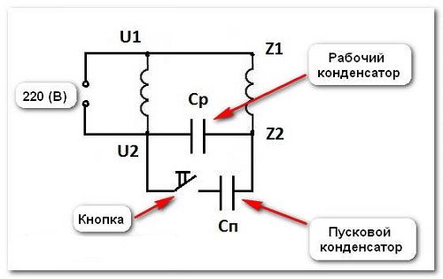
If, for example, in the passport of the electric motor, its supply voltage is 220/380, then the motor is connected to a single-phase network according to the scheme shown in Fig. 1
Rice. 1 circuit diagram inclusion of a three-phase electric motor in a network of 220 v., where
C p - working capacitor;
C p - starting capacitor;
P1 - package switch
After switching on the package switch P1, the contacts P1.1 and P1.2 close, after that you must immediately press the button \\\"Acceleration\\\". After a set of revolutions, the button is released. The motor is reversed by switching the phase on its winding with the SA1 toggle switch.
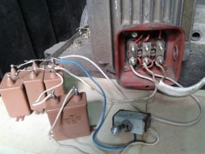
Capacity starting capacitor Cn is chosen 2..2.5 times the capacity of the working capacitor. These capacitors must be rated for 1.5 times the mains voltage. For a 220 V network, it is better to use capacitors of the MBGO, MBPG, MBGCH type with an operating voltage of 500 V and higher. Under the condition of short-term switching on, electrolytic capacitors of the K50-3, EGC-M, KE-2 types with an operating voltage of at least 450 V can also be used as starting capacitors.
For greater reliability, electrolytic capacitors are connected in series, connecting their negative terminals to each other, and shunted with a resistor R1 with a resistance of 200 ... 300 Ohm
Resistor R1 is needed to \\\"drain\\\" the remaining electric charge on the capacitors. The total capacitance of the connected capacitors will be (C1 + C2) / 2.
In practice, the value of the capacities of the working and starting capacitors is chosen depending on the engine power according to Table. 1
Three-phase power
engine, kW 0.4 0.6 0.8 1.1 1.5 2.2
Minimum capacity
working capacitor
Wed, µF 40 60 80 100 150 230
Minimum capacity
starting capacitor
Wed, µF 80 120 160 200 250 300
It should be noted that for an electric motor with a capacitor start in idle mode, a current flows 20 ... 30% more than the nominal current through the winding fed through the capacitor. In this regard, if the engine is often used in underloaded mode or idle, then in this case the capacitance of the capacitor Cp should be reduced. It may happen that during an overload the electric motor has stopped, then to start it, the starting capacitor is connected again, removing the load altogether or reducing it to a minimum.
The capacity of the starting capacitor Sp can be reduced when starting the motors at idle or with a small load. To turn on, for example, an AO2 electric motor with a power of 2.2 kW at 1420 rpm, you can use a working capacitor with a capacity of 230 microfarads, and a starting capacitor with a capacity of 150 microfarads. In this case, the electric motor starts confidently with a small load on the shaft.
The use of electrolytic capacitors in motor starting circuits
 When turning on three-phase asynchronous electric motors in a single-phase network, as a rule, ordinary paper capacitors are used. Practice has shown that instead of bulky paper capacitors, oxide (electrolytic) capacitors can be used, which are smaller and more affordable in terms of purchase. An equivalent replacement scheme for conventional paper is given in the figure.
The positive half-wave of alternating current passes through the chain VD1, C1, and the negative VD2, C2. Based on this, it is possible to use oxide capacitors with a permissible voltage that is half as much as for conventional capacitors of the same capacity. For example, if a 400 V paper capacitor is used in a circuit for a single-phase network with a voltage of 220 V, then when replacing it, according to the above scheme, you can use electrolytic capacitor for a voltage of 200 V. In the above diagram, the capacitances of both capacitors are the same and are selected similarly to the method for choosing paper capacitors for a starting device.
Schematic diagram of switching on three-phase motor into a single-phase network using electrolytic capacitors.
In the above diagram, SA1 is the motor rotation direction switch, SB1 is the motor acceleration button, electrolytic capacitors C1 and C3 are used to start the motor, C2 and C4 are used during operation.
Selection of electrolytic capacitors in the circuit of fig. 7 is best done with a clamp meter. The currents are measured at points A, B, C and the equality of currents at these points is achieved by stepwise selection of capacitor capacities. Measurements are carried out with a loaded engine in the mode in which it is supposed to operate. Diodes VD1 and VD2 for a 220 V network are selected with a reverse maximum allowable voltage of at least 300 V. The maximum forward current of the diode depends on the motor power. For electric motors up to 1 kW, diodes D245, D245A, D246, D246A, D247 with a direct current of 10 A are suitable. With a larger engine power from 1 kW to 2 kW, you need to take more powerful diodes with the corresponding forward current, or put several less powerful diodes in parallel by installing them on radiators.
ATTENTION should be paid to the fact that if the diode is overloaded, its breakdown may occur and alternating current will flow through the electrolytic capacitor, which can lead to its heating and explosion.
Inclusion of powerful three-phase motors in a single-phase network.
The capacitor circuit for connecting three-phase motors to a single-phase network allows you to get no more than 60% of the rated power from the motor, while the power limit of the electrified device is limited to 1.2 kW. This is clearly not enough for the operation of an electric planer or electric saw, which should have a power of 1.5 ... 2 kW. The problem in this case can be solved by using a larger electric motor, for example, with a power of 3...4 kW. This type of motors are designed for voltage of 380 V, their windings are connected \\\"star\\\" and there are only 3 outputs in the terminal box. The inclusion of such an engine in a 220 V network leads to a decrease in the rated power of the engine by 3 times and by 40% when operating in a single-phase network. This reduction in power renders the motor unusable, but can be used to spin the rotor idle or with minimal load. Practice shows that most of of electric motors confidently accelerates to the rated speed, and in this case, the starting currents do not exceed 20 A.
The easiest way to transfer a powerful three-phase motor into operation is to convert it to a single-phase operation, while receiving 50% of the rated power. Switching the motor to single-phase mode requires a little refinement. The terminal box is opened and it is determined from which side of the motor housing cover the winding leads fit. Loosen the screws securing the cover and remove it from the engine housing. Find the junction of the three windings at a common point and solder to common point additional conductor with a section corresponding to the section of the winding wire. The twist with a soldered conductor is insulated with electrical tape or a PVC tube, and an additional output is pulled into the terminal box. After that, the housing cover is installed in place.
During the acceleration of the engine, the windings \\\"star\\\" are used with the connection of the phase-shifting capacitor Sp. In operating mode, only one winding remains connected to the network, and the rotation of the rotor is maintained by pulsating magnetic field. After switching the windings, the capacitor Sp is discharged through the resistor Rp. The operation of the presented scheme was tested with an AIR-100S2Y3 type engine (4 kW, 2800 rpm) installed on a home-made woodworking machine and showed its effectiveness.
 The disadvantage of the proposed scheme for connecting a powerful three-phase electric motor to a single-phase network can be considered the sensitivity of the motor to overloads. If the load on the shaft reaches half the engine power, then the speed of rotation of the shaft may decrease until it stops completely. In this case, the load is removed from the motor shaft. The switch is transferred first to the position \\\"Acceleration\\\", and then to the position \\\"Work\\\" and continue further work.
Published with the permission of the author.
Content:Quite often there is a need for a non-standard connection of an electrical appliance, in relation to specific conditions. Among options it is necessary to highlight the connection of a three-phase motor to a single-phase network, which is widely used in living conditions. This scheme fully justifies itself, despite a slight decrease in the power of the connected equipment.
Connecting a three-phase motor to a single-phase network through a capacitor
Connecting a three-phase motor to a 220 volt network is quite simple. In a standard situation, each phase has its own sinusoid. Between them there is a phase shift of 120 degrees. This ensures smooth rotation of the electromagnetic field in the stator.
Each wave has an amplitude of 220 volts, which makes it possible to connect a three-phase motor to a conventional network. Three sinusoids are obtained from one phase using a conventional capacitor, provided that . Combined into a single ring, they allow you to get a phase shift of 45 and 90 degrees, quite sufficient for not too active work shaft.
The use of a capacitor makes it possible to achieve motor power in one phase of approximately 50-60% of the same indicator for three phases. However this scheme not suitable for all electric motors, so you should choose the most suitable model, for example, APN, AO, A, AO2 series and others.
One of the conditions for using a capacitor is the need to change its capacitance in accordance with the number of revolutions. The practical fulfillment of this condition is serious problem, so the motor control is performed in a two-stage version. During startup, two capacitors are connected at once, one of which is disconnected after acceleration. Only the worker remains, continuing to function.
How to choose a capacitor for a three-phase motor
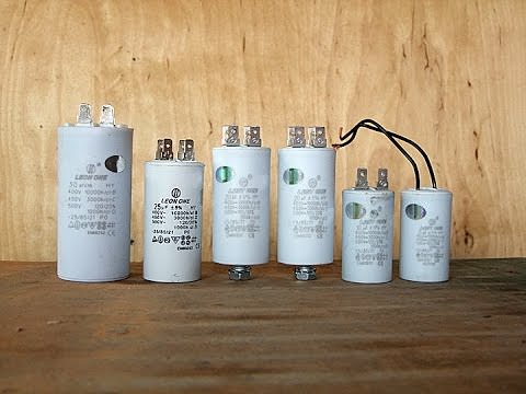
The starting capacitor should be approximately 2-2.5 times the capacity of the working capacitor. The rated voltage of these devices is typically 1.5 times the mains voltage. For 220 volt networks the best option there will be capacitors MBPG, MBGO, MBGCH, the operating voltage of which is 500 volts or more. If the capacitors are switched on only for a short time, it is possible to use electrolytic devices in the circuit, such as KE-2, K50-3, EGC-M with a minimum voltage of 450 volts.
Between themselves, the capacitors are connected in series, through negative terminals. Next, a resistor is added to the circuit, with a resistance of 200-300 Ohms, removing the remaining electric charge from capacitors.
Capacitor calculation for a three-phase motor
The normal operation of a three-phase capacitor-started motor depends on a number of conditions. One of them is to change the capacitance of the device in accordance with the number of revolutions of the engine. This is achieved through a two-stage control consisting of two capacitors - starting and working.

During start-up, the contacts close, after which the acceleration button is pressed. After a sufficient number of revolutions has been gained, the button should be released. You can calculate the working capacitance using the following formula: Cp = 4800x I / U, where Cp is the device capacitance in microfarads, I is the current consumed by the motor in amperes, U is the voltage electrical network in volts. This formula is suitable for connecting the motor windings using the delta method. If the motor windings are connected by a star, the formula Cp \u003d 2800x I / U is applied.
Thus, connecting a three-phase motor to a single-phase network has its own characteristics. For example, the capacitance of the starting and running capacitor must match the power of the connected motor.
As is known, for starting a three-phase electric motor(ED) with a squirrel-cage rotor from a single-phase network, a capacitor is most often used as a phase-shifting element. In this case, the capacitance of the starting capacitor should be several times greater than the capacitance working capacitor. For ED most commonly used in household(0.5 ... 3 kW), the cost of starting capacitors is commensurate with the cost of an electric motor. Therefore, it is desirable to avoid the use of expensive starting capacitors that operate only for a short time. At the same time, the use of workers, constantly on phase-shifting capacitors can be considered appropriate, since they allow you to load the engine by 75 ... 85% of its power with a 3-phase connection (without capacitors, its power is reduced by about 50%).
The torque, which is quite sufficient to start the indicated EM from a single-phase network 220 V / 50 Hz, can be obtained by shifting the currents in phase in the phase windings of the EM, using bidirectional electronic keys for this, which are switched on at a certain time.
Based on this, to start 3-phase electric motors from a single-phase network, the author developed and debugged two simple circuits. Both schemes were tested on EM with a power of 0.5 ... 2.2 kW and showed very good results (start-up time is not much longer than in three-phase mode). The circuits use triacs controlled by pulses of different polarity, and a symmetrical dinistor, which generates control signals during each half-cycle of the supply voltage.
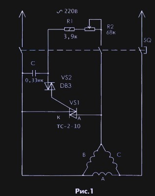
The first scheme (Fig. 1) designed to start EM with a rated speed equal to or less than 1500 rpm, the windings of which are connected in a triangle. The scheme was taken as the basis of this scheme, which is simplified to the limit. In this circuit, an electronic key (triac VS1) provides a current shift in the "C" winding at a certain angle (50 ... 70 °), which provides sufficient torque.
The phase shifter is an RC circuit. By changing the resistance R2, a voltage is obtained on the capacitor C, shifted relative to the supply voltage by a certain angle. A VS2 symmetrical dynistor is used as a key element in the circuit. At the moment when the voltage on the capacitor reaches the switching voltage of the dinistor, it will connect the charged capacitor to the control output of the triac VS1 i will turn on this bidirectional power switch.
The second scheme (Fig. 2) is intended for starting an EM with a nominal rotational speed of 3000 rpm, as well as for electric motors operating on mechanisms with a large starting resistance moment. In these cases, much more Starting torque. Therefore, the connection scheme of the EM windings "open star" (Fig. 14, c), which provides the maximum starting torque, was applied. IN specified scheme phase-shifting capacitors are replaced by two electronic keys One key is connected in series with the “A” phase winding and creates an “inductive” (lagging) one in it
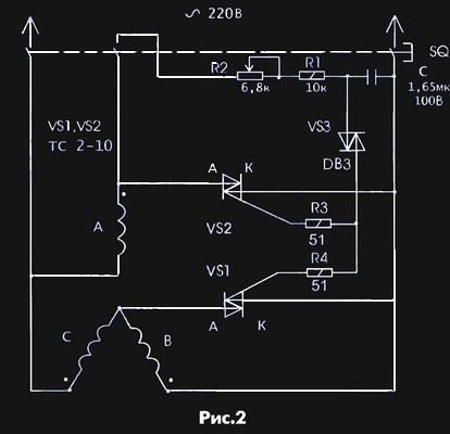
current shift, the second one is connected in parallel to the “B” phase winding and creates a “capacitive” (leading) current shift in it. It takes into account the fact that the EM windings themselves are displaced in space by 120 electrical degrees relative to each other.
Adjustment consists in the selection of the optimal current shift angle in the phase windings, at which the EM is reliably started. This can be done without using special devices. It is performed as follows.
The voltage supply to the EM is carried out by a push starter of the “manual” type PNVS-10, through the middle pole of which a phase-shifting chain is connected. The contacts of the middle pole are closed only when the "Start" button is pressed.
By pressing the "Start" button, by rotating the trimmer resistance R2, the required starting torque is selected. This is done when setting up the circuit shown in fig.2.
When setting up a schema fig.1 due to the passage of large starting currents, for some time (before turning), the ED hums and vibrates strongly. In this case, it is better to change the value of R2 in steps at relieved stress, and then, by briefly applying voltage, check how the EM starts. If at the same time the voltage shift angle is far from optimal, then the EM buzzes and vibrates very strongly. As it approaches the optimal angle, the engine “tries” to rotate in one direction or another, and at the optimal one it starts quite well.
The author debugged the circuit shown in fig.1, on ED 0.75 kW 1500 rpm and 2.2 kW 1500 rpm, and the circuit shown in fig.2, for ED 2.2 kW 3000 rpm.
Wherein empirically it has been established that it is possible to preliminarily select the values of R and C of the phase-shifting chain corresponding to the optimal angle. To do this, you need to connect a 60 W incandescent lamp in series with a key (triac) and turn them on ~ 220 V. By changing the value of R, you need to set the voltage on the lamp 1 70 V (for the circuit Fig. 1) and 1 00 V (for the circuit Fig. 2). These voltages were measured with a pointer device of the magnetoelectric system, although the shape of the voltage at the load is not sinusoidal.
It should be noted that the optimal current shift angles can be achieved with various combinations of R and C values of the phase-shifting chain, i.e. changing the value of the capacitance of the capacitor, you will have to select the corresponding resistance value.
Details
The experiments were carried out with triacs TS-2-10 and TS-2-25 without radiators. In this scheme, they worked very well. You can also use other triacs with bipolar control for the corresponding operating currents and voltage class not lower than 7. When using imported triacs in a plastic case, they should be installed on radiators.
The DB3 symmetrical dinistor can be replaced by the domestic KR1125. It has a slightly lower switching voltage. Perhaps this is better, but this dinistor is very difficult to find on sale.

Capacitors C are any non-polar, designed for an operating voltage of at least 50 V (preferably 100 V). You can also use two polar capacitors connected in series-opposite (in the circuit fig.2 their value should be 3.3 microfarads each).
The appearance of the electric drive of the grass chopper with the described start-up scheme and ED 2.2 kW 3000 rpm is shown in photo 1.
V. V. Burloko, Moriupol
Literature
1. // Signal. - 1999. - No. 4.
2. S.P. Fursov Use of three-phase
electric motors at home. - Chisinau: Kartya
moldovenske, 1976.
As you know, when a three-phase asynchronous motor is connected to a single-phase network, according to common capacitor circuits: "triangle" or "star", the motor power is used only by half (depending on the motor used).
In addition, it is difficult to start the engine under load.
The proposed article describes the method of connecting the engine without power loss.
In various amateur electromechanical machines and devices, three-phase asynchronous motors with a squirrel-cage rotor are most often used. Unfortunately, three-phase network in everyday life - an extremely rare phenomenon, therefore, amateurs use a phase-shifting capacitor to power them from a conventional electrical network, which does not allow to fully realize the power and starting characteristics of the engine. The existing trinistor "phase-shifting" devices further reduce the power on the motor shaft.
A variant of the diagram of a device for starting a three-phase electric motor without power loss is shown on rice. 1.
The windings of the 220/380 V motor are connected in a triangle, and the capacitor C1 is connected, as usual, in parallel with one of them. The capacitor is "helped" by the inductor L1, connected in parallel to another winding. With a certain ratio of the capacitance of the capacitor C1, the inductance of the inductor L1 and the load power, it is possible to obtain a phase shift between the voltages on the three branches of the load, equal to exactly 120 °.
On rice. 2 given vector diagram voltage for the device shown in fig. 1, with a purely resistive load R in each branch. The linear current Il in vector form is equal to the difference between the currents Iz and Ia, and in absolute value it corresponds to the value If√3, where If=I1=I2=I3=Ul/R is the phase load current, Ul=U1=U2=U3=220 V — line voltage networks. 
A voltage Uc1=U2 is applied to the capacitor C1, the current through it is equal to Ic1 and is ahead of the voltage by 90° in phase.
Similarly, the voltage UL1=U3 is applied to the inductor L1, the current through it IL1 lags behind the voltage by 90°.
If the absolute values of the currents Ic1 and IL1 are equal, their vector difference at right choice capacitance and inductance can be equal to Il.
The phase shift between the currents Ic1 and IL1 is 60°, so the triangle of the vectors Il, Ic1 and IL1 is equilateral, and their absolute value is Ic1=IL1=Il=If√3. In turn, the phase load current If \u003d P / ZUL, where P is the total load power.
In other words, if the capacitance of the capacitor C1 and the inductance of the inductor L1 are chosen such that when a voltage of 220 V is applied to them, the current through them would be equal to Ic1=IL1=P/(√3⋅Ul)=P/380, shown in rice. 1 circuit L1C1 will provide on the load three-phase voltage with precise phase shift.
Table 1
| P, W | IC1=IL1,A | C1, uF | L1, H |
|---|---|---|---|
| 100 | 0.26 | 3.8 | 2.66 |
| 200 | 0.53 | 7.6 | 1.33 |
| 300 | 0.79 | 11.4 | 0.89 |
| 400 | 1.05 | 15.2 | 0.67 |
| 500 | 1.32 | 19.0 | 0.53 |
| 600 | 1.58 | 22.9 | 0.44 |
| 700 | 1.84 | 26.7 | 0.38 |
| 800 | 2.11 | 30.5 | 0.33 |
| 900 | 2.37 | 34.3 | 0.30 |
| 1000 | 2.63 | 38.1 | 0.27 |
| 1100 | 2.89 | 41.9 | 0.24 |
| 1200 | 3.16 | 45.7 | 0.22 |
| 1300 | 3.42 | 49.5 | 0.20 |
| 1400 | 3.68 | 53.3 | 0.19 |
| 1500 | 3.95 | 57.1 | 0.18 |
IN tab. 1 current values Ic1=IL1 are given. capacitor capacitance C1 and inductance L1 for various values full power purely active load.
The real load in the form of an electric motor has a significant inductive component. As a result line current lags in phase from the active load current by a certain angle φ of the order of 20 ... 40 °.
 On the nameplates of electric motors, it is usually not the angle that is indicated, but its cosine - the well-known cosφ, equal to the ratio of the active component of the linear current to its full value.
The inductive component of the current flowing through the load of the device shown in rice. 1, can be represented as currents passing through some inductors Ln connected in parallel active resistance loads (Fig. 3a), or, equivalently, in parallel with C1, L1 and network wires.
From rice. 3b it can be seen that since the current through the inductor is antiphase to the current through the capacitance, the inductors LH reduce the current through the capacitive branch of the phase-shifting circuit and increase through the inductive one. Therefore, in order to maintain the phase of the voltage at the output of the phase-shifting circuit, the current through the capacitor C1 must be increased and reduced through the coil
 The vector diagram for a load with an inductive component becomes more complicated. Its fragment, which allows to produce necessary calculations, shown on rice. 4.
The total linear current Il is decomposed here into two components: active Ilcosφ and reactive Ilsinφ.
As a result of solving the system of equations for determining required values currents through capacitor C1 and coil L1:
IC1sin30° + IL1sin30° = Ilcosφ, IC1cos30° - IL1cos30° = Ilsinφ, 
we obtain the following values of these currents:
IC1 = 2/√3⋅Ilsin(φ+60°), IL1 = 2/√3⋅Ilcos(φ+30°).
With a purely active load (φ=0), the formulas give the previously obtained result Ic1=IL1=Il.
On rice. 5 the dependences of the ratios of the currents Ic1 and IL1 to Il on cosφ are given, calculated by these formulas
The same ratios can be used with a good degree of accuracy for typical values of cosφ equal to 0.85...0.9.
table 2
| P, W | IC1, A | IL1, A | C1, uF | L1, H |
|---|---|---|---|---|
| 100 | 0.35 | 0.18 | 5.1 | 3.99 |
| 200 | 0.70 | 0.35 | 10.2 | 2.00 |
| 300 | 1.05 | 0.53 | 15.2 | 1.33 |
| 400 | 1.40 | 0.70 | 20.3 | 1.00 |
| 500 | 1.75 | 0.88 | 25.4 | 0.80 |
| 600 | 2.11 | 1.05 | 30.5 | 0.67 |
| 700 | 2.46 | 1.23 | 35.6 | 0.57 |
| 800 | 2.81 | 1.40 | 40.6 | 0.50 |
| 900 | 3.16 | 1.58 | 45.7 | 0.44 |
| 1000 | 3.51 | 1.75 | 50.8 | 0.40 |
| 1100 | 3.86 | 1.93 | 55.9 | 0.36 |
| 1200 | 4.21 | 2.11 | 61.0 | 0.33 |
| 1300 | 4.56 | 2.28 | 66.0 | 0.31 |
| 1400 | 4.91 | 2.46 | 71.1 | 0.29 |
| 1500 | 5.26 | 2.63 | 76.2 | 0.27 |
IN tab. 2 the values of the currents IC1, IL1 flowing through the capacitor C1 and the inductor L1 are given at various values the total load power having the above value cosφ = √3/2.
For such a phase-shifting circuit, capacitors MBGO, MBGP, MBGT, K42-4 are used for an operating voltage of at least 600 V or MBGCH, K42-19 for a voltage of at least 250 V.
The choke is easiest to make from a rod-shaped power transformer from an old tube TV. The no-load current of the primary winding of such a transformer at a voltage of 220 V usually does not exceed 100 mA and has a non-linear dependence on the applied voltage.
If a gap of the order of 0.2 ... 1 mm is introduced into the magnetic circuit, the current will increase significantly, and its dependence on voltage will become linear.
The network windings of the TC transformers can be connected so that Rated voltage they will be 220 V (jumper between pins 2 and 2 "), 237 V (jumper between pins 2 and 3") or 254 V (jumper between pins 3 and 3"). Mains voltage is most often applied to pins 1 and 1 " . Depending on the type of connection, the inductance and current of the winding change.
IN tab. 3 the values of the current in the primary winding of the transformer TC-200-2 are given when a voltage of 220 V is applied to it at various gaps in the magnetic circuit and different switching on of the winding sections.
Data mapping tab. 3 and 2 allows us to conclude that the specified transformer can be installed in a phase-shifting motor circuit with a power of approximately 300 to 800 W and, by selecting the gap and the winding switching circuit, obtain the required current value.
The inductance also varies depending on the in-phase or anti-phase connection of the network and low-voltage (for example, incandescent) windings of the transformer.
The maximum current may slightly exceed the rated current in operation. In this case, to facilitate thermal regime it is advisable to remove everything from the transformer secondary windings, part of the low-voltage windings can be used to power the automation circuits of the device in which the electric motor operates.
Table 3
| Gap in magnetic circuit, mm |
Current in the network winding, A, when connecting leads to voltage, V |
||
|---|---|---|---|
| 220 | 237 | 254 | |
| 0.2 | 0.63 | 0.54 | 0.46 |
| 0.5 | 1.26 | 1.06 | 0.93 |
| 1 | - | 2.05 | 1.75 |
IN tab. 4 given nominal values of currents primary windings transformers of various TVs and approximate motor power values with which it is advisable to use a phase-shifting LC circuit should be calculated for the maximum possible load of the electric motor.
Table 4
| Transformer | Nominal current, A |
Power engine, W |
|---|---|---|
| TS-360M | 1.8 | 600...1500 |
| TS-330K-1 | 1.6 | 500...1350 |
| ST-320 | 1.6 | 500...1350 |
| ST-310 | 1.5 | 470...1250 |
| TSA-270-1, TSA-270-2, TSA-270-3 |
1.25 | 400...1250 |
| TS-250, TS-250-1, TS-250-2, TS-250-2M, TS-250-2P |
1.1 | 350...900 |
| TS-200K | 1 | 330...850 |
| TS-200-2 | 0.95 | 300...800 |
| TS-180, TS-180-2, TS-180-4, TS-180-2V |
0.87 | 275...700 |
With a smaller load, the necessary phase shift will no longer be maintained, but the starting performance will improve compared to using a single capacitor.
Experimental verification was carried out both with a purely active load and with an electric motor.
The active load functions were performed by two parallel-connected incandescent lamps with a power of 60 and 75 W, included in each load circuit of the device. (see fig. 1), which corresponded total power 400 W According to tab. 1 the capacitance of capacitor C1 was 15 microfarads. required current 1.05 A.
The voltages U1, U2, U3 measured on the load circuits differed from each other by 2...3 V, which confirmed the high symmetry of the three-phase voltage.
Experiments were also carried out with a three-phase asynchronous motor with a squirrel-cage rotor AOL22-43F with a power of 400 W. He worked with a capacitor C1 with a capacity of 20 microfarads (by the way, the same as when the engine was running with only one phase-shifting capacitor) and with a transformer, the gap and connection of the windings of which are selected from the condition for obtaining a current of 0.7 A.
As a result, it was possible to quickly start the engine without a starting capacitor and significantly increase the torque felt when braking the pulley on the engine shaft.
Unfortunately, it is difficult to conduct a more objective check, since in amateur conditions it is almost impossible to provide a normalized mechanical load on the engine.
It should be remembered that the phase-shifting circuit is a series oscillatory circuit tuned to a frequency of 50 Hz (for the purely active load option), and this circuit cannot be connected to the network without load. 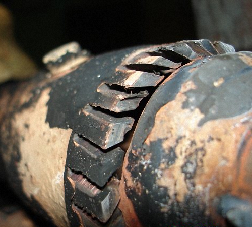
 (1 ratings, on average: 5,00 out of 5)

