How is a capacitor selected? Determination of capacitances of phase-shifting capacitors. Run and start capacitors
Asynchronous motors are widely used in industry. But electric units of small power can be successfully used in everyday life. It needs a rotating magnetic field to function.
However single phase motors will not rotate without a phase shift created, which is organized using additional winding and a phase shifter. As the latter, MAL2118 capacitors are suitable.
Capacitor can be connected various methods. There are three different schemes:
- launcher;
- working;
- mixed.
It is worth noting that the most common scheme is the first (launcher). Her distinguishing feature is that the capacitor is connected to the motor network only at the time of its start.
Then the electric unit independently maintains its rotation. Such a switching scheme allows not only saving money on installing a complete set (wires of a smaller cross section), but also saving on electricity.
It must not be forgotten that there is a very likely risk of overheating, which in most cases depends on the terrain in which the engine is used. As a protection, it is recommended to install a thermal relay.
The indicated scheme is beneficial primarily in that it allows you to correct distortions. magnetic field, thereby reducing eddy current losses and increasing efficiency.
The capacitor remains on for the entire period of engine operation. However, in this method there is a fly in the ointment. Switching on with a running capacitor significantly degrades the starting characteristics of an asynchronous machine.
It is for this reason that engineers advise to come to a compromise and use two schemes at once, combined into one.
Due to the use of two schemes at once, starting characteristics will be average (quite acceptable in terms of resource use).
Remember! Before switching on with a capacitor, it is imperative to evaluate the performance using a multimeter. electrical element(even if it's brand new).
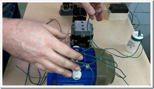
Alexander Shenrok will clearly demonstrate the methods for starting an asynchronous motor using a capacitor:
The easiest way to turn on a three-phase electric motor in single-phase network, this is with a single phase-shifting capacitor. As such a capacitor, only non-polar capacitors should be used, and not field (electrolytic).
phase shifting capacitor.
When connecting a three-phase electric motor to a three-phase network, the start is provided by an alternating magnetic field. And when the motor is connected to a single-phase network, a sufficient shift of the magnetic field is not created, so a phase-shifting capacitor must be used.
The capacitance of the phase-shifting capacitor must be calculated as follows:
- for connection "triangle": SF=4800 I/U;
- for connection "star":SF=2800 I/U.
Learn more about these types of connections. :
In these formulas: Cf is the capacitance of the phase-shifting capacitor, μF; I– rated current, A; U– mains voltage, V.
In this formula, there are such abbreviations: P is the power of the electric motor, necessarily in kW; cosph is the power factor; n- Engine efficiency.
The power factor or displacement of current to voltage, as well as the efficiency of the electric motor, is indicated in the passport or on the plate (nameplate) on the motor. The values of these two indicators are often the same and most often equal to 0.8-0.9.
Roughly, you can determine the capacitance of a phase-shifting capacitor as follows: Cf \u003d 70 P. It turns out that for every 100 W you need 7 microfarads of capacitor capacitance, but this is not accurate.
Ultimately, the correctness of determining the capacitance of the capacitor will show the operation of the electric motor. If the engine does not start, then the capacity is low. In the case when the engine is very hot during operation, it means that there is a lot of capacity.
working capacitor.
The capacitance of the phase-shifting capacitor found by the proposed formulas is only sufficient to start a three-phase electric motor that is not loaded. That is, when there are no mechanical gears on the motor shaft.
The calculated capacitor will ensure the operation of the electric motor even when it reaches its operating speed, therefore such a capacitor is also called a work capacitor.

Start capacitor.
It was previously said that an unloaded electric motor, that is, a small fan, a grinding machine can be started from one phase-shifting capacitor. Here, run drilling machine, a circular saw, a water pump can no longer be started from one capacitor.
To start a loaded electric motor, you need to briefly add capacitance to the existing phase-shifting capacitor. Specifically, it is necessary to connect another phase-shifting capacitor in parallel to the connected working capacitor. But only for a short time of 2 - 3 seconds. Because when the electric motor picks up high speeds, an overestimated current will flow through the winding to which two phase-shifting capacitors are connected. High current will heat the motor winding and destroy its insulation.
A capacitor connected additionally and in parallel to an existing phase-shifting (working) capacitor is called a starting capacitor.
For lightly loaded electric motors of fans, circular saws, drilling machines, the capacitance of the starting capacitor is chosen equal to the capacitance of the working capacitor.
For loaded motors of water pumps, circular saws, you need to choose the capacity of the starting capacitor twice as much as that of the worker.
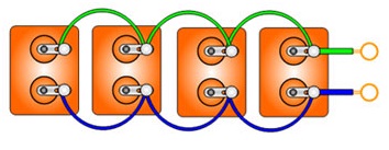
Very convenient for exact selection required containers phase-shifting capacitors(working and starting) to assemble a battery of capacitors connected in parallel. Capacitors connected together must be taken small containers 2, 4, 10, 15 uF.
When choosing the voltage of any capacitor, you need to use the universal rule. The voltage for which the capacitor is designed must be 1.5 times higher than the voltage where it will be connected.
added comment on youtube:everything is a little easier. In any sane textbook, with the title “ Electric cars”, at the end of the section on the theory of an asynchronous motor, the question of the operation of an asynchronous machine in a single-phase mode is considered, with various schemes winding connections. There are also formulas for calculating the capacity of working and starting capacitors. Accurate calculation, is quite complicated - you need to know the specific parameters of the engine. A simplified calculation method is as follows: Star Srab = 2800 (Inom / Uset); Descent \u003d Srab 2 ÷ 3 (under difficult launch conditions, multiplicity 5); Triangle Srab = 4800 (Inom / Uset); Descent \u003d Srab 2 ÷ 3 (under difficult launch conditions, multiplicity 5); where, Srab is the capacitance of the working capacitor, uF; Descent - the capacity of the starting capacitor, uF; Inom - nominal phase current engine at rated load, A; Uset - voltage of the network to which the motor will be connected, V. Calculation example. Initial data: we have an asynchronous electric motor - 4 kW; winding connection diagram -Δ / Y voltage U - 220 / 380 V; current I - 8 / 13.9 A. According to the motor currents: 8 A is the phase current (i.e. the current of each of the three windings) of the motor on a triangle and a star, and it is also line current on a star; 13.9 A is the linear current of the motor on the triangle (we will not need it in the calculations). Well, and, in fact, the calculation itself: Star Srab = 2800 (Inom / Uset) = 2800 (8 / 220) = 101.8 uF Descent = Srab 2÷3 = 101.8 2÷3 = 203.6÷305, 4 uF (under difficult starting conditions - 509 uF) Triangle Sb = 4800 (Inom / Uset) = 4800 (8 / 220) = 174.5 uF Trigger = Sb 2÷3 = 174.5 2÷3 = 349÷523, 5 uF (under difficult starting conditions - 872.5 uF) Type of working capacitor - polypropylene (imported SVV-60 or domestic equivalent - DPS). The voltage of the conduit is not less than 400 V in alternation (an example of marking: AC ~ 450 V), for Soviet paper MBGOs, the working voltage should be at least 500 V, if less - connect in series, but this is a loss of capacity, of course - so many conduits will have to be dialed) . For starting capacitors, it is better, of course, to also use polypropylene or paper ones, but this will be expensive and cumbersome. To reduce the cost, you can take polar electrolytic ones (these are those that have “+” and / or “-” on the case), having previously made one non-polar electrolyte from two polar electrolytes, connecting two capacitors with minuses together (you can also connect with pluses, but of some capacitors, the minus is connected to the body of these conders and if you connect them with pluses, then you will have to isolate these conders not only from the surrounding hardware, but also from each other, otherwise a short circuit), and leave the remaining two pluses for connection to the motor windings (not forget that when serial connection two identical capacitors, their total capacitance is halved, and the operating voltage is doubled - for example, by connecting in series (minus to minus) two 400 V 470 uF capacitors, we get one non-polar conder with an operating voltage of 800 V and a capacity of 235 uF). The operating voltage of each of the two series-connected electrolytes must be at least 400 V. We gain the required starting capacity (if necessary) by parallel connection of such dual (i.e. already non-polar) electrolytes - with parallel connection capacitors, the operating voltage remains unchanged, and the capacitances are summed up (same as with parallel connection of batteries). It is possible not to invent this “collective farm” with dual electrolytes - there are ready-made starting non-polar electrolytes - for example, the CD-60 type. But, in any case, with electrolytes (both non-polar, and even more so with polar ones) there is one BUT - such capacitors can be connected to a 220 V network (it is better not to turn on polar ones at all) only for the time the engine is started - electrolytes cannot be used as working capacitors - explode (polar ones almost immediately, non-polar ones a little later). With a working capacitor on the triangle, the engine loses 25-30% of its three-phase power, on the star 45-50%. Without a working capacitor, depending on the winding connection scheme, the power loss will be more than 60%. And one more thing about conduits: there are a lot of videos on youtube where people pick up working capacitors by the sound of the engine at idle (no load) and, being frightened by the increased hum of the engine, reduce the capacity of working capacitors until this hum drops to more or less acceptable. This is the wrong selection of a working conduit - this is how the engine power under load is underestimated. Yes, the increased buzz of the motor is not very good, but not too dangerous for the windings, if the capacity of the working capacitor is not too high. The fact is that, ideally, the capacity of the working capacitor should change smoothly, depending on the load of the engine - the greater the load, the greater the capacity should be. But to make such a smooth adjustment of the capacity is quite difficult, it is both expensive and cumbersome. Therefore, they select a capacity that will correspond to a specific motor load - usually nominal. With the capacity of the working capacitor design load motor, the stator magnetic field is circular and the buzz is minimal. But when the capacity of the working capacitor exceeds the motor load, the stator magnetic field becomes elliptical, pulsating, uneven, and this pulsating magnetic field causes a buzz, due to the uneven rotation of the rotor - the rotor, rotating in one direction, simultaneously twitches forward and then back , and with increased currents in the windings, the motor develops less power. Therefore, if the motor hums at medium loads and at idle, then this is not so scary, but if the hum is observed at full load, then this indicates a clearly overestimated capacity of the working conduit. In this case, a decrease in capacitance will reduce the currents in the motor windings and its heating, even out (“round off”) the stator magnetic field (i.e., reduce hum) and increase the power developed by the motor. But leave the engine idling for a long time with a working conduit designed for full power the engine is still not worth it - in this case, there will be an increased voltage on the working capacitor (up to 350 V), and an increased current will flow through the winding connected in series with the working capacitor (30% more than the nominal one - on the triangle, and 15% - on a star). With an increase in the load on the motor, the voltage on the working capacitor and the current in the motor winding connected in series with the working capacitor will decrease.
When connected asynchronous motor in a single-phase 220/230 V network, it is necessary to provide a phase shift on the stator windings in order to simulate a rotating magnetic field (VMF), which causes the motor rotor shaft to rotate when connected to its “native” three-phase networks alternating current. Known to many who are familiar with electrical engineering, the ability of a capacitor to give an electric current a “head start” by π / 2 \u003d 90 ° compared to voltage, does a good job, as it creates the necessary moment that makes the rotor rotate in already “non-native” networks.
But the capacitor for these purposes must be selected, and must be done with high accuracy. That is why the readers of our portal are provided with an absolute free use of a calculator for calculating the capacitance of the working and starting capacitor. After the calculator, the necessary explanations will be given on all its points.
Calculator for calculating the capacitance of the working and starting capacitors
If you look inside the case of any electrical appliance, you can see many different components used in modern circuitry. Understand how all these connected in single system resistors, transistors, diodes and microcircuits are quite difficult. However, in order to understand why a capacitor is needed in electrical circuits enough knowledge school course physics.
Capacitor device and its properties
The capacitor consists of two or more electrodes - plates, between which a dielectric layer is placed. This design has the ability to accumulate electric charge when connected to a voltage source. The dielectric may be air or solids: paper, mica, ceramics, oxide films.
The main characteristic of the capacitor - constant or variable electrical capacitance, measured in farads. It depends on the area of the plates, the gap between them and the type of dielectric. The capacitance of a capacitor determines its two most important properties: the ability to store energy and the dependence of conductivity on the frequency of the transmitted signal, due to which this component has been widely used in electrical circuits.
Energy storage
If connect flat capacitor to a constant voltage source, negative charges will gradually accumulate on one of its electrodes, and positive charges on the other. This process, called charging, is shown in the figure. Its duration depends on the capacitance values and active resistance chain elements.

The presence of a dielectric between the plates prevents the flow of charged particles inside the device. But in the chain itself at this time electricity will exist until the voltages on the capacitor and the source are equal. Now, if you disconnect the battery from the tank, it will itself be a kind of battery capable of delivering energy if a load is connected.
Resistance versus current frequency
A capacitor connected to an AC circuit will periodically recharge in accordance with the change in polarity of the supply voltage. Thus, the considered electronic component, along with resistors and inductors, creates resistance Rс=1/(2πfC), where f is the frequency, C is the capacitance.
As can be seen from the presented dependence, the capacitor has a high conductivity with respect to high-frequency signals and weakly conducts low-frequency ones. Resistance capacitive element in chain direct current will be infinitely large, which is equivalent to its rupture.
After studying these properties, you can consider why a capacitor is needed and where it is used.
Where are capacitors used?
- Filters are devices in radio-electronic, energy, acoustic and other systems designed to transmit signals in certain frequency ranges. For example, in the usual charger For mobile phone capacitors are used to smooth the voltage by suppressing high-frequency components.
- Oscillatory contours of electronic equipment. Their work is based on the fact that when capacitors are turned on in conjunction with an inductor, periodic voltages and currents arise in the circuit.
- Pulse shapers, timers, analog computing devices. In the operation of these systems, the dependence of the capacitor charge time on the capacitance value is used.
- Rectifiers with voltage multiplication, used, among other things, in X-ray installations, lasers, particle accelerators. Here the most important role is played by the property of the capacitive component to accumulate energy, store and give it away.
Of course, these are only the most common devices where capacitors are used. Not a single complex household, automotive, industrial, telecommunications, power electronic equipment can do without them.
 (1 ratings, on average: 5,00 out of 5)

