Two-phase AC motors. Single-phase asynchronous motors. Device and principle of operation
Easy voltage conversion alternating current has made it the most widely used in power supply. In the field of designing electric motors, another advantage of alternating current has been discovered: the ability to create a rotating magnetic field without additional transformations or with a minimum number of them.
Therefore, even despite certain losses due to the reactive (inductive) resistance of the windings, the ease of creating AC electric motors contributed to the victory over DC power supply at the beginning of the 20th century.
Basically, AC electric motors can be divided into two groups:
Asynchronous
In them, the rotation of the rotor differs in speed from the rotation of the magnetic field, due to which they can operate at a wide variety of speeds. This type of AC motor is the most common nowadays. Synchronous
These motors have a rigid connection between the rotor speed and the rotation speed of the magnetic field. They are more difficult to produce and less flexible in use (changes in speed when fixed frequency supply network is possible only by changing the number of stator poles).
They are used only at high powers of several hundred kilowatts, where their greater efficiency compared to asynchronous electric motors significantly reduces heat losses.
AC ELECTRIC MOTOR ASYNCHRONOUS
The most common type of asynchronous motor is an electric motor with a squirrel-cage rotor of the “squirrel cage” type, where a set of conductive rods are placed in the inclined grooves of the rotor, connected at the ends by rings.
The history of this type of electric motor goes back more than a hundred years, when it was noticed that a conductive object placed in the gap of the core of an alternating current electromagnet tends to break out of it due to the occurrence of an induced emf with an opposite vector in it.
Thus, an asynchronous motor with a squirrel-cage rotor does not have any mechanical contacting units other than the rotor support bearings, which provides motors of this type with not only low price, but also the highest durability. Thanks to this, electric motors of this type have become the most common in modern industry.
However, they also have certain disadvantages that have to be taken into account when designing asynchronous electric motors of this type:
High starting current– since at the moment the asynchronous brushless electric motor is connected to the network, active resistance The stator winding is not yet affected by the magnetic field created by the rotor; a strong surge of current occurs, several times greater than the rated current consumption.
This feature of the operation of motors of this type must be included in all designed power supplies in order to avoid overloads, especially when connecting asynchronous electric motors to mobile generators with limited power.
Short Starting torque – electric motors with squirrel-cage windings have a pronounced dependence of torque on speed, so turning them on under load is extremely undesirable: the time to reach the nominal mode and starting currents increase significantly, the stator winding is overloaded.
This, for example, happens when you turn on deep well pumps– in their power supply circuits it is necessary to take into account a five to sevenfold current reserve.
Inability to directly start in circuits single-phase current - in order for the rotor to start rotating, a starting push or the introduction of additional phase windings, shifted in phase relative to each other, is necessary.
For start asynchronous electric motor AC in a single-phase network uses either a manually switched starting winding, which is turned off after spinning the rotor, or a second winding connected through a phase-shifting element (most often a capacitor of the required capacity).
Lack of possibility of obtaining high rotation speed- although the rotation of the rotor is not synchronized with the rotation frequency of the stator magnetic field, it cannot advance it, therefore the network is 50 Hz maximum speed for an asynchronous electric motor with a squirrel-cage rotor – no more than 3000 rpm.
Increasing the rotation speed of an asynchronous motor requires the use of frequency converter(inverter), which makes such a system more expensive than a brushed motor. In addition, as the frequency increases, reactive losses increase.
Difficulty in organizing reverse- this requires a complete stop of the engine and re-switching of the phases, in the single-phase version - a phase shift in the starting or second phase winding.
It is most convenient to use an asynchronous electric motor in an industrial three-phase network, since the creation of a rotating magnetic field is carried out by the phase windings themselves without additional devices.
In fact, a chain consisting of three phase generator and electric motor, can be considered as an example of an electric transmission: the generator drive creates a rotating magnetic field in it, converted into oscillations electric current, in turn exciting the rotation of the magnetic field in the electric motor.
In addition, it is with three-phase power supply that asynchronous electric motors have the highest efficiency, since in a single-phase network the magnetic field created by the stator can essentially be decomposed into two antiphase ones, which increases useless losses due to oversaturation of the core. Therefore, powerful single-phase electric motors are usually made using a commutator circuit.
AC ELECTRIC MOTOR COLLECTOR
In electric motors of this type, the magnetic field of the rotor is created by phase windings connected to the commutator. Actually a brushed AC motor is different from a motor direct current only by what is included in its calculation reactance windings
In some cases, universal commutator motors are even created, where the stator winding has a tap from an incomplete part for inclusion in the alternating current network, and a direct current source can be connected to the full length of the winding.
The advantages of this type of engine are obvious:
Ability to operate at high speeds allows you to create commutator electric motors with a rotation speed of up to several tens of thousands of revolutions per minute, familiar to everyone from electric drills.
No need for additional starting devices in contrast to squirrel-cage motors.
High starting torque, which speeds up the return to operating mode, including under load. Moreover, the torque of the commutator electric motor is inversely proportional to the speed and, as the load increases, allows one to avoid a drop in the rotation speed.
Ease of speed control- since they depend on the supply voltage, to adjust the rotation speed in within the widest range It is enough to have a simple triac voltage regulator. If the regulator fails, the commutator motor can be connected directly to the network.
Less rotor inertia- it can be made much more compact than with a short-circuit circuit, due to which the commutator motor itself becomes noticeably smaller.
Also, the commutator motor can simply be reversed, which is especially important when creating various types of power tools and a number of machine tools.
For these reasons, commutator motors are widespread in all single-phase consumers where flexible speed control is necessary: in hand power tool, vacuum cleaners, kitchen appliances and so on. However, a number design features determines the specifics of operation of a commutator electric motor:
Commutator motors require regular replacement of brushes, which wear out over time. The collector itself also wears out, while an engine with a squirrel-cage rotor, as already written above, provided that the bearings are replaced infrequently, is practically eternal.
The inevitable sparking between the commutator and the brushes (the reason for the appearance of the familiar smell of ozone during operation of a commutator electric motor) not only further reduces the service life, but also requires increased safety measures during operation due to the likelihood of ignition of flammable gases or dust.
© 2012-2017 All rights reserved.
All materials presented on this site are for informational purposes only and cannot be used as guidelines or regulatory documents.
Areas of use. Low power asynchronous motors (15 - 600 W) are used in automatic devices and electrical household appliances for driving fans, pumps and other equipment that do not require speed control. Single-phase micromotors are usually used in household appliances and automatic devices, since these appliances and devices are usually powered by a single-phase AC network.
The principle of operation and design of a single-phase motor. Stator winding of a single-phase motor (Fig. 4.60, A) located in grooves occupying approximately two-thirds of the stator circumference, which corresponds to a pair of poles. As a result
(see Chapter 3) the distribution of MMF and induction in the air gap is close to sinusoidal. Since alternating current passes through the winding, the MMF pulsates in time with the frequency of the network. Induction at an arbitrary point in the air gap
B x = In m sinωtcos (πх/τ).
Thus, in a single-phase motor, the stator winding creates a stationary flux that varies with time, and not a circular rotating flux, as in three-phase motors with a symmetrical supply.
To simplify the analysis of the properties of a single-phase motor, let us present (4.99) in the form
B x = 0.5V t sin (ωt - πх/τ) + 0.5V t sin (ωt + πх/τ),.
that is, we replace the stationary pulsating flow with a sum of identical circular fields rotating in opposite directions and having the same rotation frequencies: n 1pr = n 1rev = n 1 . Since the properties of an asynchronous motor with a circular rotating field are discussed in detail in § 4.7 - 4.12, the analysis of the properties of a single-phase motor can be reduced to considering the combined action of each of the rotating fields. In other words, a single-phase motor can be represented as two identical motors, the rotors of which are rigidly connected to each other (Fig. 4.60, b), with the magnetic fields and the torques created by them rotating in the opposite direction M at M arr. A field whose direction of rotation coincides with the direction of rotation of the rotor is called direct; reverse direction field - reverse or inverse.
Let us assume that the direction of rotation of the rotors coincides with the direction of one of the rotating fields, for example with n ave. Then the sliding of the rotor relative to the flow F etc
s pr = (n 1pr - n 2)/n 1pr = (n 1 - n 2)/n 1 = 1 - n 2 /n 1..
Rotor slip relative to the flow F arr.
s arr = (n 1arr + n 2)/n 1arr = (n 1 + n 2)/n 1 = 1 + n 2 /n 1..
From (4.100) and (4.101) it follows that
s o6p = 1 + n 2 /n 1 = 2 - s pr..
Electromagnetic moments M at M the reverse generated by the forward and reverse fields are directed in opposite directions, and the resulting torque of a single-phase motor M cut is equal to the difference in torque at the same rotor speed.
In Fig. 4.61 shows the dependency M = f(s) for a single-phase motor. Looking at the figure, we can draw the following conclusions:
a) a single-phase motor has no starting torque; it rotates in the direction in which it is driven by an external force; b) the rotation speed of a single-phase motor at idle is less than that of three phase motor, due to the presence of a braking torque generated by the reverse field;
c) the performance characteristics of a single-phase motor are worse than those of a three-phase motor; it has increased slip at rated load, lower efficiency, lower overload capacity, which is also explained by the presence of a reverse field;
d) the power of a single-phase motor is approximately 2/3 of the power of a three-phase motor of the same size, since in a single-phase motor the working winding occupies only 2/3 of the stator slots. Fill all stator slots
since in this case the winding coefficient is small, copper consumption increases by approximately 1.5 times, while power increases only by 12%.
Starting devices. To obtain starting torque, single phase motors have a starting winding shifted by 90 electrical degrees relative to the main working winding. During the start-up period, the starting winding is connected to the network through phase-shifting elements - capacitance or active resistance. After the engine has finished accelerating, the starting winding is turned off, while the engine continues to operate as a single-phase one. Since the starting winding operates only for a short time, it is made from a wire of a smaller cross-section than the working one, and is placed in a smaller number of grooves.
Let us consider in detail the start-up process when using capacitance C as a phase-shifting element (Fig. 4.62, a). On the starting winding P voltage
Ú
1p = Ú
1 - Ú
C= Ú
1 +jÍ 1 P X C, i.e. it is phase shifted relative to the mains voltage U 1 attached to the working winding R. Consequently, the current vectors in the working I 1p and launcher I 1p windings are shifted in phase by a certain angle. By choosing a container in a certain way phase shifting capacitor, it is possible to obtain an operating mode at start-up that is close to symmetrical (Fig. 4.62, b), i.e., to obtain a circular rotating field. In Fig. 4.62, dependencies are shown M = f(s) for the engine with the starting winding turned on (curve 1) and off (curve 2). The engine is started in parts ab characteristics 1; at the point b the starting winding is turned off, and then the engine runs in parts сО characteristics 2.
Since turning on the second winding significantly improves mechanical characteristics motor, in some cases single-phase motors are used, in which windings A and B
turned on all the time (Fig. 4.63, a). Such motors are called capacitor motors.
Both windings of capacitor motors usually occupy same number grooves and have the same power. When starting a capacitor motor, to increase the starting torque, it is advisable to have an increased capacitance C p + C p. After accelerating the motor according to characteristic 2 (Fig. 4.63, b) and reducing the current, part of the capacitors Cn is turned off so that at rated mode (when the motor current becomes smaller, than at start-up) increase the capacitance and ensure engine operation in conditions close to operation in a circular rotating field. In this case, the engine operates at characteristic 1.
Capacitor motor has a high cos φ. Its disadvantages are the relatively large mass and dimensions of the capacitor, as well as the occurrence of a non-sinusoidal current when the supply voltage is distorted, which in some cases leads to harmful effects on the communication line.
Under easy starting conditions (small load torque during the starting period), motors with starting resistance are used R(Fig. 4.64, a). The presence of active resistance in the starting winding circuit provides a smaller phase shift φ p between voltage and current in this winding (Fig. 4.64, b) than the phase shift φ p in the working winding. In this regard, the currents in the working and starting windings are shifted in phase by an angle φ p - φ p and form an asymmetrical (elliptical) rotating field, due to which the starting torque occurs. Motors with starting resistance are reliable in operation and are mass-produced. The starting resistance is built into the motor housing and is cooled by the same air that cools the entire motor.
Single-phase micromotors with shielded poles. In these motors, the stator winding connected to the network is usually concentrated and mounted on salient poles (Fig. 4.65, a), the sheets of which are stamped together with the stator. At each pole, one of the tips is covered by an auxiliary winding consisting of one or more short-circuited turns that shield from 1/5 to 1/2 of the pole arc. The motor rotor is a squirrel-cage conventional type.
The magnetic flux of the machine created by the stator winding (pole flux) can be represented as the sum of two components (Fig. 4.65, b) F p = F p1 + F p2, where F p1 is the flux passing through the part of the pole not covered by the short-circuit with this twist; F p2 is the flux passing through the part of the pole shielded by a short-circuited coil.
Flows Фп1 and Фп2 pass through different parts of the pole piece, i.e., they are displaced in space by an angle β. In addition, they are phase shifted relative to the MMF F n stator windings at different angles - γ 1 and γ 2. This is explained by the fact that each pole of the described motor can be considered, to a first approximation, as a transformer, the primary winding of which is the stator winding, and the secondary winding is a short-circuited turn. The stator winding flux induces an emf in the short-circuited coil E to (Fig. 4.65, c), as a result of which a current arises I k and MDS F k, folding with MDS F n stator windings. Reactive current component I k reduces the flow Ф p2, and the active one shifts it in phase relative to the MMF F n. Since the flow F p1 does not cover the short-circuited turn, the angle γ 1 has a relatively small value (4-9°) - approximately the same as the phase shift angle between the transformer flow and the MDS primary winding in idle mode. The angle γ 2 is much larger (about 45°), i.e., the same as in a transformer with secondary winding short-circuited (for example, in a measuring current transformer). This is explained by the fact that the power losses, on which the angle γ 2 depends, are determined not only by the magnetic power losses in the steel, but also by the electrical losses in the short-circuited turn.
Rice. 4.65. Design diagrams of a single-phase motor with shielded poles and its
vector diagram:
1
- stator; 2 -
stator winding; 3 -
short-circuited
turn; 4 -
rotor; 5
- pole
Flows Фп1 and Фп2, displaced in space by an angle β and shifted in phase in time by an angle γ = γ 2 - γ l, form an elliptical rotating magnetic field (see Chapter 3), which produces a torque acting on the rotor of the motor in the direction from the first pole piece, not covered by the short-circuited turn, to the second tip (in accordance with the alternation of maximum fluxes of the “phases”).
To increase the starting torque of the engine in question by bringing its rotating field closer to a circular one, various ways: magnetic shunts are installed between the pole pieces of adjacent poles, which strengthen the magnetic connection between the main winding and the short-circuited turn and improve the shape of the magnetic field in the air gap; increase the air gap under the tip, which is not covered by the short-circuited turn; use two or more short-circuited turns on one tip with different coverage angles. There are also motors without short-circuited turns on the poles, but with an asymmetrical magnetic system: different configurations individual parts poles and different air gaps. Such motors have a lower starting torque than motors with shaded poles, but their efficiency is higher, since they have no power losses in short-circuited turns.
The considered designs of motors with shaded poles are irreversible. To implement reverse in such engines, instead of short-circuited turns, coils are used B1, B2, B3 And AT 4(Fig. 4.65, V), each of which covers half a pole. Shorting a pair of coils IN 1 And AT 4 or AT 2 And AT 3,you can shield one or the other half of the pole and thus change the direction of rotation of the magnetic field and the rotor.
The shaded pole motor has a number of significant shortcomings: relatively large dimensions and mass; low cos φ ≈ 0.4 ÷ 0.6; low efficiency η = 0.25 ÷ 0.4 due to big losses in a short-circuited turn; small starting torque, etc. The advantages of the engine are simplicity of design and, as a result, high reliability in operation. Due to the absence of teeth on the stator, the motor noise is insignificant, so it is often used in devices for reproducing music and speech.
The 220V single-phase electric motor is a separate mechanism that is widely used for installation in a variety of devices. It can be used for household and industrial purposes. Nutrition electric motor carried out from a regular outlet, which must have a power of at least 220 Volts. In this case, you need to pay attention to the frequency of 60 hertz.
In practice, it has been proven that a single-phase 220 V electric motor is sold together with devices that help transform energy electric field , and also accumulate the necessary charge using a capacitor. Modern models, which are produced using innovative technologies, 220V electric motors are additionally equipped with equipment for illuminating the device’s workplace. This applies to internal and external parts.
It is important to remember that the capacitor capacity must be stored in compliance with all basic requirements. The best option- this is the place where air temperature remains unchanged and is not subject to any fluctuations. In room temperature regime should not drop to a minus value.
While using the engine, experts recommend measuring the capacitance value of the capacitor from time to time.
 Asynchronous motors are widely used today for various production processes. This particular model of electric motor is used for different drives. Single-phase asynchronous designs help drive woodworking machines, pumps, compressors, devices industrial ventilation, conveyors, lifts and many other equipment.
The electric motor is also used to drive small-scale mechanization equipment. These include feed choppers and concrete mixers. It is necessary to purchase such structures only from trusted suppliers. Before purchasing, it is advisable to check the certificates of conformity and warranty from the manufacturer.
Suppliers must provide their customers with service maintenance electric motor in case of its breakdown or failure. This is one of the main components that is completed during the assembly of the pump unit.
Existing series of electric motors
Today industrial enterprises produce the following series single-phase electric motor 220V:
Absolutely all engines divided by design , according to the installation method, as well as the degree of protection. This allows you to protect the structure from moisture or mechanical particles.
Features of A series electric motors
Electric single-phase motors of the A series are unified asynchronous designs. They are closed from external influences using a squirrel-cage rotor.
The structure of the electric motor has the following performance groups:
The cost of a single-phase 220V electric motor depends on the series.
What types of engines are there?
Single-phase motors are designed to equip electric drives for domestic and industrial purposes. Such designs are manufactured in accordance with state standards.
3-7. DEVICE OF ASYNCHRONOUS SINGLE-PHASE ELECTRIC MOTORS
In Fig. Figure 3-16 shows the design of an asynchronous single-phase electric motor of the AOLB type with a built-in starting resistor. The electric motor stator is assembled from stamped sheets of electrical steel 15, pressed and poured into an aluminum shell (stator housing) with double walls 13. Channels are formed between the walls for air cooling the surface of the stator. Two covers 2 and 17, cast from aluminum alloy, are put on the stator housing sharpening points.
A stamped cap 18 with holes in the end is put on the front cover 17. Through these holes, when the rotor rotates, fan 19, mounted on the end of the rotor shaft, takes in air. The fan is cast from aluminum alloy and secured to the shaft with a screw.
The stator sheets are stamped with 24 pear-shaped grooves. Of these, 16 slots are occupied by the wires of the working winding, and 8 slots are occupied by the wires of the starting winding. The output ends of the working and starting windings are brought out to the contact screws 4 located in the terminal box 11. The rotor core is assembled from sheets 12 of electrical steel and pressed onto the corrugated surface of the middle part of the shaft 1. An aluminum winding 14 with closing rings and fan blades is poured into the grooves of the rotor. The purpose of the fan is to throw heated air towards the cooled outer walls of the case.
![]()
A centrifugal switch for the starting winding is mounted on the rotor. It consists of two levers 7 with counterweights 9, sitting on axles 8, which are pressed into four fan blades. The levers are pressed with pins 6 onto the plastic sleeve 5, which sits loosely on the shaft. When the rotor accelerates, when its rotation frequency approaches the nominal value, the counterweights diverge under the influence of centrifugal force, turning the levers around the axes.
In this case, sleeve 5 moves to the right, compressing spring 10, and releases spring contact 4, which closes the starting winding circuit. When the rotor is stationary, this contact is closed by the end of the bushing with stationary contact 3.
The movable and fixed contacts are mounted on insulation board to the back cover of the electric motor 2. A thermal relay is mounted on it, which disconnects the electric motor from the network when it overheats. Stand 16 with four studs is used to mount the electric motor.
The electric motor connection diagram is shown in Fig. 3-17.
The supply voltage is supplied to terminals C 1 and C 2. From these terminals, voltage is supplied to the working winding through the contacts thermal relay RT, consisting of a winding, a bimetallic strip and contacts. When the electric motor heats up beyond the permissible limit, the plate bends and opens the contacts. At short circuit A large current will flow through the winding of the thermal relay, the plate will quickly heat up and open the contacts. In this case, the working C and starting P windings will be de-energized, since both of them are powered through a thermal relay. Thus, the thermal relay protects the electric motor from both overload and short circuits.
The starting winding is powered from terminals C 1 and C 2 through jumper C 2 - P 1, contacts of the centrifugal switch VTs, jumper VTs - RT, contacts of thermal relay RT. When starting the electric motor, when the rotor reaches a rotation speed of 70-80% of the rated speed, the contacts of the centrifugal switch will open and the starting winding will be disconnected from the network. When the electric motor is turned on, when the rotor speed decreases, the contacts of the centrifugal switch will close again and the starting winding will be prepared for the next start.
In Fig. Figure 3-18 shows the design of an asynchronous electric motor of the ABE type. These motors are connected to a network with a constantly switched on auxiliary winding, in the circuit of which a capacitor is connected in series (Fig. 3-9). Electric motors of the ABE type do not have a rigid housing and therefore they are called built-in. The electric motors are connected to the drive mechanism using a flange or bracket.
The electric motor housing is the stator core package 1, made of sheets of electrical steel 0.5 mm thick. The package is pressed and filled under pressure aluminum alloy. At the ends of the stator there are pressure rings 5 and four aluminum rods tightening them. The stator slots contain coils 6 of the working and auxiliary windings. Bearing shields 4 and 7. The ends of the windings 8 are brought out through the rubber bushing 9 in the bearing shield to connect them to the network. The bearing shields are tightened with four studs.
The rotor of the electric motor is assembled from sheets of electrical steel and filled with aluminum 2. Together with the rotor winding, fan wings are cast to cool the electric motor. The rotor rotates in two ball bearings 3.
Electric motors have alphabetic and digital type designations, for example, the AVE 041-2 electric motor is deciphered as follows: A - asynchronous, B - built-in, E - single-phase,
4 is the size number, 1 is the serial number of the length of the stator core and the number 2 separated by a dash is the number of poles.
3-8. SYNCHRONOUS SINGLE-PHASE ELECTRIC MOTORS
In some cases, electric motors are required, the rotation speed of which must be strictly constant regardless of the load. As such, synchronous electric motors are used, in which the rotor rotation speed is always equal to the rotation frequency of the magnetic field and is determined by (3-2). There are many types of synchronous electric motors, both three-phase and single-phase. Here we consider only two of the most simple type single-phase synchronous electric motors: reactive and capacitor reactive.
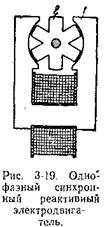
In Fig. 3-19 shown design diagram the simplest single-phase reluctance motor, known in technology as La Cura wheels. Stator 1 and rotor 2 are assembled from stamped sheets of electrical steel. A coil powered by a single-phase alternating current network is wound on the stator, creating a pulsating magnetic field. The reluctance motor got its name because the rotor rotates due to the reactions of two forces of magnetic attraction.
With a pulsating field, the electric motor has no starting torque and must be spun by hand. The magnetic forces acting on the rotor teeth always tend to place it opposite the stator poles, since in this position the resistance to the magnetic flux will be minimal. However, the rotor, by inertia, passes this position during the time when the pulsating field decreases. With the next increase in the magnetic field, magnetic forces act on another tooth of the rotor, and its rotation will continue. For stable operation, the rotor of a jet motor must have high inertia.
Jet motors operate stably only at a low rotation speed of the order of 100-200 rpm. Their power usually does not exceed 10-15 W. The rotor rotation frequency is determined by the frequency of the supply network f and the number of rotor teeth Z. Since during one half-cycle of change in the magnetic flux the rotor rotates by 1/Z turn, then in 1 minute, containing 60 2 f half-cycles, it will turn by 60 2 f/Z turns . At an alternating current frequency of 50 Hz, the rotor speed is:
![]()
To increase the torque, the number of teeth on the stator is increased. The greatest effect can be achieved by making as many teeth on the stator as on the rotor. In this case, magnetic attractions will act simultaneously not on a pair of teeth, but on all the teeth of the rotor, and the torque will increase significantly. In such electric motors, the stator winding consists of small coils that are wound around the stator rim in the spaces between the teeth. Older types of electric turntables used an electric motor with 77 teeth on the stator and rotor, which provided a disk rotation speed of 78 rpm. The rotor was integral with the disk on which the record was placed. To start the electric motor, you had to push the disk with your finger.
The stator of a synchronous capacitor reluctance motor is no different from the stator of a capacitor asynchronous motor. The rotor of an electric motor can be made from the rotor of an asynchronous electric motor by milling grooves in it according to the number of poles (Fig. 3-20). In this case, the rods of the squirrel cage are partially cut off. In the factory production of such electric motors with rotor sheets stamped with pole protrusions, part of the squirrel cage rods plays the role of a starting winding. The rotor begins to rotate in the same way as the rotor of an asynchronous electric motor, then is drawn into synchronism with magnetic field and then rotates at synchronous speed.
The quality of operation of a capacitor electric motor strongly depends on the operating mode in which the electric motor has a circular rotating field. The ellipticity of the field in synchronous mode leads to increased noise, vibration and disruption of rotation uniformity. If a circular rotating field occurs at asynchronous mode, then the electric motor has a good starting torque, but small moments of entry and exit from synchronism. When the circular field shifts towards higher frequencies, the starting torque decreases, and the moments of entry and exit from synchronism increase. The greatest moments of entry and exit from synchronism are obtained in the case when a circular rotating field takes place in a synchronous mode. In this case, however, the starting torque is greatly reduced. In order to increase it, the active resistance of the short-circuited rotor winding is usually slightly increased.

A disadvantage of some types of capacitor reluctance motors is rotor sticking, which means that when starting, the rotor does not turn, but stops in some position.
Typically, rotor sticking occurs in electric motors with an unfortunate relationship between the sizes of the dimples and pole protrusions. The highest reactive torque with a small power consumed by the electric motor is obtained when the ratio of the pole arc b p to the pole division t is approximately 0.5-0.6, and the depth of the depressions h is 9-10 times greater than the air gap between the pole protrusions and the stator.
A positive property of capacitor reluctance motors is their high power factor, which is significantly higher than that of three-phase electric motors, sometimes reaching 0.9-0.95. This is explained by the fact that the inductance of a capacitor motor is largely compensated by the capacitance of the capacitor.
Synchronous reluctance motors are the most common synchronous motors due to their simplicity of design, low cost and lack of sliding contacts. They have found application in synchronous communication circuits, in sound cinema, sound recording and television installations.
3-9. USE OF THREE-PHASE INDUCTION ELECTRIC MOTORS AS SINGLE-PHASE MOTORS
In practice, there are cases when you need to connect a three-phase electric motor to a single-phase network. Previously, it was believed that this required rewinding the stator of the electric motor. Currently, many schemes for connecting three-phase electric motors have been developed and tested in practice. single-phase network without any changes to the stator windings.

Capacitors are used as starting elements.
The stator winding terminals of a three-phase electric motor have the following designations: C1—beginning of the first phase; C2—beginning of the second phase; NW—beginning of the third phase; C4 - end of the first phase; C5 - end of the second phase; C6—end of the third phase. These designations are stamped on metal tags placed on the winding lead conductors.
The winding of a three-phase electric motor can be connected in a star (Fig. 3-21, a) or in a triangle (Fig. 3-21, b). When connecting in a star, the beginnings or ends of all three phases are connected to one point, and the remaining three terminals are connected to three-phase network. When connecting into a triangle, the end of the first phase is connected to the beginning of the second, the end of the second to the beginning of the third, and the end of the third to the beginning of the first. From the connection points, leads are taken to connect the electric motor to a three-phase network.
IN three-phase system distinguish between phase and linear voltages and currents. When connected into a star, the following relationships take place between them:
when connected in a triangle
Most three-phase electric motors are produced in two linear voltage, for example 127/220 V or 220/380 V. At lower network voltages, the winding is connected in a triangle, and at higher voltages, in a star. For such electric motors, all six output conductors of the winding are brought out to the board: clamps.
However, there are electric motors for one mains voltage, in which the winding is connected in a star or triangle inside the electric motor, and only three conductors are connected to the terminal board. Of course, in this case it would be possible to disassemble the electric motor, disconnect the interphase connections and make three additional conclusions. However, you don’t have to do this by using one of the diagrams for connecting an electric motor to a single-phase network, which are given below.
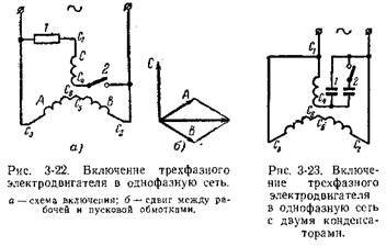
A schematic diagram of connecting a three-phase electric motor with six terminals to a single-phase network is shown in Fig. 3-22, a. To do this, two phases are connected in series and connected to a single-phase network, and the third phase is connected to them in parallel, including a starting element 1 with a switch 2. An active resistance or a capacitor can serve as a starting element. In this case, the working winding will occupy 2/3 of the stator slots, and the starting winding will occupy 1/3. Thus, three-phase winding provides the required ratio of grooves between the working and starting windings. With this connection, the angle between the working and starting windings is 90° el. (Fig. 3-22, b).
When connecting two phases in series, you must ensure that they are turned on in accordance with, and not opposite, when n. With. of connected phases are subtracted. As can be seen from the diagram in Fig. 3-22, a, c common point the ends of the second and third phases C 5 and C 6 are connected.
A three-phase electric motor can also be used as a capacitor motor according to the diagram in Fig. 3-23 with one working capacitor 1 or with working 1 and starting capacitors 2. With this connection scheme, the capacitance of the working capacitor, μF, is determined by the formula:
where I is the rated current of the electric motor, A; U—mains voltage, V.
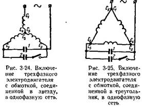
A three-phase electric motor with three terminals and a star-connected stator winding is connected to a single-phase network according to the diagram in Fig. 3-24. In this case, the capacity of the working capacitor is determined by the formula
Capacitor voltage U 1 = 1.3 U.
A three-phase electric motor with three terminals and a stator winding connected in a triangle is connected to a single-phase network according to the diagram in Fig. 3-25. The capacity of the working capacitor is determined by the formula
Capacitor voltage U=1.15 V.
In all three cases the capacity starting capacitors can be approximately determined from the relation
![]()
When choosing a connection circuit, you should be guided by the voltage for which the three-phase electric motor is designed and the voltage of the single-phase network. Wherein phase voltage three-phase
Example. Three-phase electric motor with a power of 250 W, voltage 127/220 V with rated current 2/1.15 A must be connected to a single-phase network with a voltage of 220 V.
When using the diagram in Fig. 3-24 working capacitor capacity:
![]()
voltage across the capacitor U 1 = 1.3 220 = 286 V.
Start capacitor capacity
When using a three-phase electric motor as single phase power it is reduced to 50%, as a single-phase capacitor - to 70% of the rated power of a three-phase electric motor.
N.V. Vinogradov, Yu.N. Vinogradov
How to calculate and make an electric motor yourself
Moscow 1974
 (1 ratings, on average: 5,00 out of 5)

