Three-phase winding current generator. Star connection of generator windings and electrical energy consumers
§ 62. CONNECTIONS OF GENERATOR WINDINGS
In Fig. Figure 65 shows a diagram of a generator that has three independent single-phase circuits. E.m.f. in these circuits are identical, have the same amplitudes and are shifted in phase by 1/3 of the period. Wires that supply current to the load can be connected to each pair of generator stator winding terminals. It is more profitable to combine these three phases into one common three-phase system. To do this, the generator windings are connected to each other by a star or triangle.
When connecting the generator windings with a star (Fig. 66), the ends of all three phases X, Y and Z (or the beginnings of A, B and C) are connected to each other, and wires are brought out from the beginning (or ends), discharging energy into the network. The three wires thus obtained are called linear, and the voltage between any two linear wires is linear voltages U l. From the common point of connection of the ends (or beginnings) of the three phases (from the star zero point) can
a fourth wire, called neutral, should be allocated. The voltage between any of the three linear wires and the neutral wire is equal to the voltage between the beginning and end of one phase, i.e., phase voltage U f.
Typically, all phases of the generator winding are identical so that the effective values of e. d.s. in phases are equal, i.e. E A = E B = E C. If a load is included in the circuit of each phase of the generator,

then currents will flow through these circuits. In the case of the same value and nature of the resistance of all three phases of the receiver, i.e., with a uniform load, the currents in the phases are equal in strength and are shifted in phase relative to their voltages by the same angle j. Both the maximum and effective values of phase voltages under a uniform load are equal, i.e. U A = U B = U C . These voltages are 120° out of phase, as shown in the phasor diagram (Fig. 67). The voltage between any points of the circuit (see Fig. 66) corresponds to the vectors (Fig. 67) between the same points. So, for example, the voltage between points A and O of the circuit ( phase voltage U A) corresponds to the vector A-O diagrams, and the voltage between the linear wires A and B of the circuit - to the vector of the linear voltage AB of the diagram. Using a vector diagram, it is easy to establish the relationship between linear and phase voltage. From triangle AO A we can write the following relation:

i.e., when the generator windings are connected with a star, the linear voltage is = 1.73 times greater than the phase voltage (with a uniform load).
From the diagram (see Fig. 66) it is clear that when the generator windings are connected with a star, the current in the linear wire is equal to the current in the generator phases, i.e. Il = Iph.
Based on Kirchhoff’s first law, we can write that the current in the neutral wire is equal to the geometric sum of the currents in the generator phases, i.e.
With a uniform load, the currents in the generator phases are equal to each other and are shifted in phase by 1/3 of the period. The geometric sum of the currents of the three phases in this case is zero, i.e. there will be no current in the neutral wire. Therefore, when symmetrical load neutral wire may be missing. With an asymmetrical load, the current in the neutral wire is not zero, but usually the neutral wire has a smaller cross-section than the linear ones.
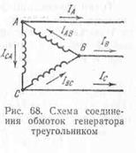
When connecting the generator windings with a triangle (Fig. 68), the beginning (or end) of each phase is connected to the end (or beginning) of the other phase. Thus, the three phases of the generator form a closed circuit in which the electric current operates. d.s, equal to the geometric sum e. d.s induced in the phases of the generator, i.e. Ea + Eb + Ec. Since e. d.s. in the generator phases are equal and shifted
for 1/3 of the period in phase, then their geometric sum is zero and, therefore, in the closed loop of a three-phase system connected by a triangle, there will be no current in the absence of an external load.
Linear wires in a delta connection are connected to the connection points between the beginning of one phase and the end of another. The voltage between the linear wires is equal to the voltage between the beginning and the end of one phase. Thus, when connecting the generator windings with a triangle, the linear voltage is equal to the phase voltage, i.e.
With a uniform load, equal currents flow in the phases of the generator windings, shifted relative to the phase voltages by equal angles j, i.e. I AB = I BC =I CA
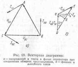
In Fig. 69, and a vector diagram is shown, which shows the vectors of phase voltages and currents.
The connection points of the phases and line wires A, B and C are branching points, and line currents are not equal to phase ones. Taking the positive direction of phase and linear currents indicated in Fig. 69, based on Kirchhoff’s first law for instantaneous current values, the following expressions can be written:
i A = i AB - i CA ; i B = i BC - i AB ; i C = i CA - i BC
Since the currents are sinusoidal, we replace the algebraic subtraction of the instantaneous values of the currents with the geometric subtraction of vectors depicting their effective values:
The current of the linear wire AI A is determined by the geometric difference: the phase current vectors I AB and I CA.
To construct the linear current vector I A, we will depict the phase current vector I AB (Fig. 69.6), from the end of which we will construct the vector -I CA, equal and oppositely directed to the vector I CA. The vector connecting the beginning of the vector I AB with the end of the vector -I CA is the linear current vector I A. Similarly, the linear current vectors I B and IC can be constructed.
When a 3-phase generator operates, an EMF is created in each of its windings in the form of a sinusoidal oscillation. All vectors are separated by 120° in rotation angle and can be described by the formulas:
e A = E m sinωt, E A = Efe j0° ;
e B =E m sin(ωt-120°), E B =Efe -j120°;
e C =E m sin(ωt-240°)=E m sin(ωt+120°), E C =Efe j120°.
To connect the generator windings to a connected system, one of two schemes is used:
- “star” (Y);
- “triangle” (Δ).
"Star". For the “star” circuit, all outputs of the stator phase windings are connected to a single common point N, called the neutral or zero point. Input (start) of windings of each phase A, B and C connect to the linear terminals of the generator.
"Triangle". For this connection diagram, the output phases are formed:
- "A" connecting the winding output A to the winding input C;
- "IN" connecting the winding output IN to the winding input A;
- "WITH" connecting the winding output WITH to the winding input IN.
Connection points A, B and C used as linear outputs for the generator.

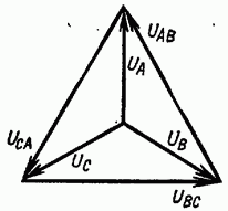
Vector diagrams. For a working generator, the windings of which are connected in a star configuration, the voltage vector diagram has the shape of an equilateral triangle with the center at the origin and located symmetrically relative to the ordinate axis.
 Its sides are represented by linear stress vectors with the direction of rotation opposite to the clockwise direction. The phase voltage vectors connect the center of the triangle with the vertices in the direction from the origin.
The term phase voltage refers to the potential difference between the common terminal N and the linear one A, B or WITH and mark: U A, U B, U C. The voltages in the generator phases are equal to the EMF of the windings: E A =U A, E B =U B, E C =U C.
The line voltage of the generator is measured between any two of its terminals and is designated by the name of the selected phases: U AB, U BC, U CA. The magnitude of the line voltage vector is determined by the geometric difference between the vectors of the corresponding phases:
U AB =U A -U B;
U BC =U B -U C;
U CA =U C -U A.
For a generator with windings connected in a “triangle” pattern, the voltage vector diagram also has the shape of an equilateral triangle, but it is rotated 30° relative to the coordinate center in the direction of clockwise movement.
 The ratios of linear and phase voltages for a generator assembled according to a “delta” circuit remain the same as for a generator operating according to a “star” circuit.
Parameter calculations three-phase networks carried out using mathematical methods (for example, the complex method) and methods of geometric addition.
To do this, select one of the vectors as the initial one and orient it in the complex plane, taking into account the direction and magnitude. The remaining vectors are completed according to the angles of their phase shift relative to the selected initial vector, taking into account their values.
It is easier to start normal calculations for a star connection circuit by determining the phase vector voltage A, which in this system leaves the origin of the complex plane in the direction to the north. Expressions of phase voltages in complex form for such a calculation are described by the formulas:
U A =Ufe j0°;
U B =Ufe -j120°;
U C =Ufe j120°.
Formulas for linear vectors have next view:
U AB =Ule j30°;
U BC =Ule -j90°;
U SA = Ule j150° .
For “triangle” circuits, the linear voltage vector is taken as the initial reference U AB. Formulas for calculating phase voltage vectors take the following expressions:
U A =Ufe -j30°;
U B =Ufe -j150°;
U C =Ufe j90°.
Linear voltage vectors are described by the formulas:
U AB = Ule j0° ;
U BC =Ule -j120°;
U SA = Ule j120° .
Having carried out geometric calculations, it is not difficult to determine the linear magnitude of the vector from the phase value:
U l =2U f cos30°=2U f √3/2=U f √3.
Important! The “delta” winding connection diagram for a generator is practically not suitable for real use, so it is prohibited to use it.
In the phases of the “triangle” circuit, a common circuit is formed, in which a total EMF arises Σe=e AB +e BC +e CA. The impedance values in the windings are small and even the total EMF is small Σe>0 causes equalizing currents in the “triangle” mains, which are comparable to the rated current value in the generator. This creates big losses energy and significantly reduces the generator efficiency.
Power engineers have a definition rated voltage for 3-phase system. They are called linear voltages, which are expressed in kilovolts (kV, kV). They are represented by values of 0.4; 1.1; 3.5; 6.3; 10.5; 22; 35; 63; 110; 220; 330; 500; 750.
For electricity consumers, the nominal value of 3-phase voltage can be indicated by the ratio of linear and phase voltages U L /U F. For a 0.4 kV power network it will look like: 380/220 volts.
Did you know,
What is a thought experiment, gedanken experiment?
This is a non-existent practice, an otherworldly experience, an imagination of something that does not actually exist. Thought experiments are like waking dreams. They give birth to monsters. Unlike a physical experiment, which is an experimental test of hypotheses, a “thought experiment” magically replaces experimental testing with desired conclusions that have not been tested in practice, manipulating logical constructions that actually violate logic itself by using unproven premises as proven ones, that is, by substitution. Thus, the main task of the applicants of “thought experiments” is to deceive the listener or reader by replacing a real physical experiment with its “doll” - fictitious reasoning on parole without the physical verification itself.
Filling physics with imaginary, “thought experiments” has led to the emergence of an absurd, surreal, confused picture of the world. A real researcher must distinguish such “candy wrappers” from real values.
Relativists and positivists argue that “thought experiments” are a very useful tool for testing theories (also arising in our minds) for consistency. In this they deceive people, since any verification can only be carried out by a source independent of the object of verification. The applicant of the hypothesis himself cannot be a test of his own statement, since the reason for this statement itself is the absence of contradictions in the statement visible to the applicant.
We see this in the example of SRT and GTR, which have turned into a kind of religion that controls science and public opinion. No amount of facts that contradict them can overcome Einstein’s formula: “If a fact does not correspond to the theory, change the fact” (In another version, “Does the fact not correspond to the theory? - So much the worse for the fact”).
The maximum that a “thought experiment” can claim is only the internal consistency of the hypothesis within the framework of the applicant’s own, often by no means true, logic. This does not check compliance with practice. Real verification can only take place in an actual physical experiment.
An experiment is an experiment because it is not a refinement of thought, but a test of thought. A thought that is self-consistent cannot verify itself. This was proven by Kurt Gödel.
When connecting the windings in a star, the ends of the windings X, Y, Z are connected to one point, called the zero point or neutral of the generator (Fig. 7-5). In a four-wire system, the neutral or neutral wire is connected to the neutral. Three linear wires are connected to the beginning of the generator windings.
The voltages between the beginnings and ends of the phases, or, what is the same, the voltages between each of the linear wires and the neutral wire are called phase voltages and are designated or in general form
Neglecting the voltage drop in the generator windings, we can consider the phase voltages equal to the corresponding e. d.s. induced in the generator windings.
The voltages between the beginnings of the windings, or, what is the same, between linear wires, are called linear voltages and are designated or in general terms
Let us establish the relationship between linear and phase voltages when connecting the generator windings with a star.

Rice. 7-5. Star connection diagram of generator windings.

Rice. 7-6. Vector diagram three-phase circuit voltages.
Since the end of the first phase X is connected not to the beginning of the second phase, but to its end Y, which is similar to the counter connection of two sources of energy. d.s. at constant current, then the instantaneous value of the linear voltage between wires A and B will be equal to the difference in the corresponding phase voltages, i.e.
similarly instantaneous values of other linear voltages
Thus, the instantaneous value of the line voltage is equal to the algebraic difference of the instantaneous values of the corresponding phase voltages.
Since they change according to a sinusoidal law and have the same frequency, the linear voltages will also change sinusoidally, and the effective values of the linear voltages can be determined from the vector diagram (Fig. 7-6):
From the above it follows that the linear voltage vector is equal to the difference between the vectors of the corresponding phase voltages.
Phase voltages are shifted from each other by 120°. To determine the linear voltage vector, you need to geometrically subtract the vector from the voltage vector, or, what is the same, add a vector - equal in magnitude and opposite in sign.
Similarly, we obtain the linear voltage vector as the difference between the voltage vectors and the linear voltage vector as the difference between the vectors and OA.
By lowering the perpendicular from the end of an arbitrary phase voltage vector, for example, to the linear voltage vector, we obtain a right triangle OHM, from which it follows that
![]()
![]()
Rice. 7-7. Vector diagram of voltages when connecting the generator windings with a star.
From the vector diagram (Fig. 7-6) and the last formula it follows that the effective value of the line voltage is several times greater effective value phase voltage and that the linear voltage is 30° ahead of the phase voltage; by the same angle the linear voltage leads the phase voltage and voltage-phase voltage
Adjacent, linear voltages are shifted relative to each other at the same angles (120°) as adjacent phase voltages. The star of the linear voltage vectors is rotated in the positive direction relative to the star of the phase voltage vectors at an angle of 30°.
It is necessary to pay attention to the fact that the obtained relationships between linear and phase voltages take place only with a symmetrical voltage system.
Since the linear voltage vectors are defined as the differences between the phase voltage vectors, by connecting the ends of the phase voltage vectors forming a star, we obtain a triangle of linear voltage vectors (Fig. 7-7).
Example 7-1. Determine the linear voltage of the generator if its phase voltage is 127 and 220 V.
If the phase voltage is 220 V, then
 (1 ratings, on average: 5,00 out of 5)

