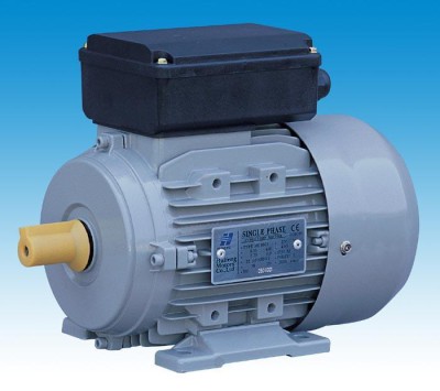
Electric motor 220V with starting winding. Single-phase electric motors
There are 2 types of single-phase asynchronous motors - bifilar (with a starting winding) and capacitor. Their difference is that in bifilar single-phase motors the starting winding operates only until the motor accelerates. Afterwards it is turned off by a special device - a centrifugal switch or a start-up relay (in refrigerators). This is necessary because after overclocking it reduces efficiency.

In capacitor single-phase motors, the capacitor winding runs all the time. Two windings - main and auxiliary, they are shifted relative to each other by 90°. Thanks to this, you can change the direction of rotation. The capacitor on such engines is usually attached to the housing and is easy to identify by this feature.
Connection diagram for a single-phase motor via a capacitor
When connecting a single-phase capacitor motor, there are several options for connection diagrams. Without capacitors, the electric motor hums, but does not start.
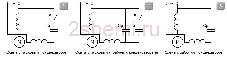
- 1 circuit - with a capacitor in the power supply circuit of the starting winding - starts well, but during operation the power it produces is far from rated, but much lower.
- 3, the connection diagram with a capacitor in the connection circuit of the working winding gives the opposite effect: not very good performance at start-up, but good performance. Accordingly, the first circuit is used in devices with heavy starting, and with a working capacitor - if good performance characteristics are needed.
- Diagram 2 - connections single phase motor- install both capacitors. It turns out something between the options described above. This scheme is used most often. She's in the second picture. When organizing this circuit, you also need a PNVS type button, which will connect the capacitor only during the start time, until the motor “accelerates”. Then two windings will remain connected, with the auxiliary winding through a capacitor.

Connection diagram for a three-phase motor via a capacitor
Here, the voltage of 220 volts is distributed into 2 series-connected windings, where each is designed for this voltage. Therefore, the power is lost almost twice, but such an engine can be used in many low-power devices.

The maximum power of a 380 V motor in a 220 V network can be achieved using a delta connection. In addition to minimal power losses, the engine speed also remains unchanged. Here, each winding is used for its own operating voltage, hence the power.
It is important to remember: three-phase electric motors have more high efficiency than single-phase 220 V. Therefore, if there is a 380 V input, be sure to connect to it - this will ensure more stable and economical operation of the devices. To start the motor, you will not need various starters and windings, because a rotating magnetic field appears in the stator immediately after connecting to the 380 V network.
Online calculation of motor capacitor capacity
|
Enter data for calculating capacitors - motor power and efficiency |
There is a special formula that can be used to calculate the required capacity exactly, but it’s quite possible to get by online calculator or recommendations that are derived from many experiences:
The working capacitor is taken at the rate of 0.8 μF per 1 kW of engine power;
The launcher is selected 2-3 times more.
Capacitors must be non-polar, that is, not electrolytic. The operating voltage of these capacitors must be at least 1.5 times higher than the network voltage, that is, for a 220 V network we take capacitors with an operating voltage of 350 V and higher. To make starting easier, look for a special capacitor in the starting circuit. They have the words Start or Starting in their markings.
 Starting capacitors for motors
 These capacitors can be selected using the method from smallest to largest. Having thus selected the average capacity, you can gradually add and monitor the operating mode of the engine so that it does not overheat and has enough power on the shaft. Also starting capacitor select adding until it starts smoothly without delay.
At normal operation three-phase asynchronous electric motors with capacitor starting, connected to a single-phase network, it is assumed that the capacitor capacitance changes (decrease) with increasing shaft speed. At the moment of starting asynchronous motors (especially with a load on the shaft) in a 220 V network, increased capacity is required phase shifting capacitor.
Reversing the direction of movement of the engine
If, after connecting, the motor works, but the shaft does not rotate in the direction you want, you can change this direction. This is done by changing the windings of the auxiliary winding. This operation can be performed by a two-position switch, the central contact of which is connected to the output from the capacitor, and to the two outer terminals from “phase” and “zero”.
The topic is very popular and raises many questions. First, let's figure out what types of asynchronous electric motors are alternating current and in what cases is connection via capacitors used? Then we will look at the diagrams and formulas for selecting capacitors.
Motors are divided into three-phase and single-phase according to the method of power supply. First, let's look at connecting a three-phase electric motor through a capacitor.
Briefly about three-phase asynchronous electric motors
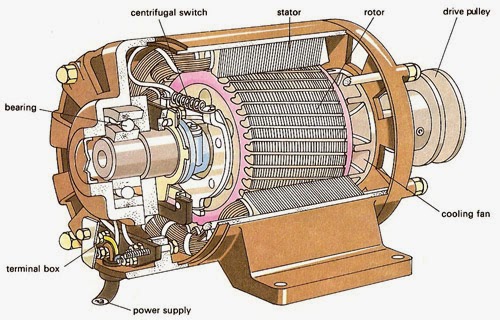
Three-phase asynchronous electric motors are widely used in various industries, Agriculture, everyday life The electric motor consists of a stator, a rotor, a terminal box, shields with bearings, a fan and a fan casing.
I did not remove the tightening pins to get to the stator with the rotor. But the protruding part on which the fan sits is the rotor. The rotor is the rotating part, the stator is stationary (it is not visible in the figure).
Next, let's look at the terminal block more carefully. On one side we have C1-C2-C3, and below - C4-C5-C6. These are the beginnings and ends of the motor phase windings. We have three phases, since the motor is three-phase - C1-C4, C2-C5, C3-C6. There is also a rusty grounding bolt in the photo; it is located in the terminal block on the top left.
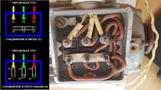
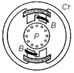
The connection that is visible in the photograph is called a “star”. I already wrote - similarly for electric motors. On the side of the photo I added what a schematic star and triangle look like for this electric motor. The whole difference is in the location of the jumpers. Their combinations determine the ED connection scheme.
operation of a three-phase electric motor without one phase at a constant load
The electric motor can be powered by single-phase network and without additional measures and schemes. For example, if one of the phases is damaged. However, in this case the rotation speed will decrease. Reducing the rotation speed will lead to an increase in slip, which in turn will cause an increase in motor current.
And an increase in current will lead to heating of the windings. In such a situation, it is necessary to unload the ED to 50%. Operation in this mode is possible, however, if the engine stops, it will not be possible to start again.
why are capacitors used to start from a single-phase network?
A restart will not occur, since the magnetic field of the stator will be pulsating and, in short, due to the direction of certain vectors in opposite directions, the rotor will be motionless. In order for the engine to start, we need to change the location of these vectors. For this purpose, elements are used that shift the phases of vectors. Let's consider a circuit that implements this feature.

In the diagram we see that the winding is divided into two branches - starting and working. The starting one is used from the beginning of the start until the engine turns, then it is turned off and only the working one is used. To turn off the launcher, you can use a button, for example. Press and hold until the engine turns, and then release and the chain is broken.
Phase-shifting elements can be resistors or capacitors. The difference in the use of one or the other in form magnetic field. And to put it simply, they choose capacitors, since with one value starting torque, lower starting current will be when using capacitors.
And with the same starting currents, circuits with a capacitor will have a greater initial torque, that is, the engine will accelerate faster, which is undoubtedly better for operation.
Important: connection via capacitors is made for motors up to 1.5 kV. It is calculated that for more powerful EDs the cost capacitive elements will exceed the cost of the engine itself, therefore, their installation is unprofitable. Although, if you get them for free, which is not uncommon in our area, then you can try it.
how to connect an electric motor through a capacitor
Since capacitors are more profitable in many ways for starting electric motors, we will analyze a couple of starting circuits using capacitors. For the “delta” connection diagram and for the “star” connection diagram.

The starting branch will be used until the motor turns around, the working branch will be used throughout the entire operation of the engine.
capacitors for starting an electric motor

Exist various schemes and in each capacitors are selected differently. For the circuits given above, the selection of capacitors is carried out according to two formulas:
star scheme:
Working capacity= 2800*Inom.ed/Unetwork
triangle diagram:
Working capacity = 4800*Inom/Unetwork
The starting capacity in both cases is taken equal to 2-3 of the working capacity.
In the formulas above, Inom is rated current motor phases. If you look at a plate where two currents are indicated through a fraction, it will be the smaller of them. Umains - supply voltage (~127, ~220). This means that we have calculated the capacitance and the next step is to know the voltage across the capacitor. For the circuits shown in the figures above, the voltage on the capacitor is equal to 1.15 of the mains voltage. But this is AC voltage, and to select capacitors you need to know the voltage direct current. This is where we need a small sign:
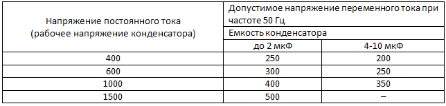
For example, the network voltage is ~220, multiply by 1.15 and we get 253. In the table we look at the variable 250 corresponds to a constant of 400V for a capacitance of up to 2 µF, or 600V for capacitances of 4-10 µF. It is necessary that the rated voltage of the capacitor is equal to or greater than the calculated one.
So, step by step, we figured out how to connect a three-phase asynchronous electric motor to a single-phase network and what you need to calculate and know for this. There are other schemes for connecting a motor through a capacitor, but we will consider these issues another time in another article.
If you don’t want to lose this material, then share it with your friends on social networks!
A single-phase motor can be commutator or squirrel-cage. With a commutator motor, everything is quite simple: the two wires coming out of the motor housing are plugged into a socket - the connection is made. You will have to tinker with connecting a single-phase motor with a squirrel-cage rotor. It's all about defining the conclusions.
Parallel working winding (RO) in a single-phase motor it is connected launcher (software) to create at least some kind of rotating magnetic field.
Single-phase motor with four terminals has permanent connection software. It operates in tandem with the main one, without disconnecting, only the connection is made through (Fig.a). The connection diagram for such a single-phase motor is very convenient, since all the wiring is easily accessible, they can be swapped using a switch for execution (Fig. a1). 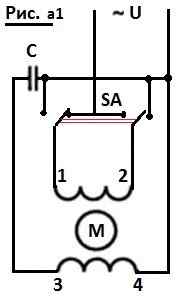 They can be determined without much difficulty: call with an ohmmeter and find the ringing pairs.
For example, an ohmmeter determined a closed circuit of the first terminal with the second, and of the third with the fourth. This means that 1 and 2 are one winding, 3 and 4 are another. We connect the fourth wire to the second (or the first to the third, it doesn’t matter) - this is common. does not matter. Next, all connections according to figure a or a1.
A little more difficult to deal with motor with three outgoing cores. In such cases, the software is connected for a short time: the engine has spun up, and it turns off, otherwise it will burn out. How does this kind of switching happen?
This is what they came up with start-protective relay. Its function is not only to connect the software, but also to create its optimal shutdown time. 
During startup through electromagnetic coil a large current passes. At this moment, its core is retracted and acts on the contact that controls the software (Fig. 1 and 2). After starting, the current drops, the core is released, and the starting circuit is broken.
With an interturn short circuit the current in the working winding is constantly high, the software remains in operation, the engine begins to smoke. Built in for protection thermal relay with a bimetallic plate, disconnecting X3 from the network.
If the engine turns on and off for a short time, then the thermal protection is triggered. The reason is either an interturn short circuit or a low (high) network voltage.
Pay attention to the strange, at first glance, Figure 3. This is the cover from the starter-protective device, which shows the marking of the wires connected to it and an arrow. Everything is clear with the markings - do not confuse the ends when connecting. And here the arrow indicates the position of the relay in space: It should always face up. While still a novice electrician, I repaired a washing machine. Turned it upside down. It turned out that all I needed to do was replace the belt. I replaced it, tried to turn it on - it started working... and started smoking, the engine burned out.
After some time, I learned that on an inverted relay, the contact remains closed, whereas in the normal position, under the force of gravity, after the coil is turned off, it falls down. And I just ended up at the bottom in an overturned car. To test turn it on, you just had to turn the device over so that the arrow would point upward again.
How is it done? connecting a single-phase motor with unknown three wires? The resistance of the PO (X1-X3) is several times greater than the resistance of the RO (X2-X3). X3 comes out from the junction of PO and PO (see Fig. b).
First, let's mark the wires so as not to get confused (the same X1, X2 and X3). We measure the resistance, for example, between X1 and X2, it turns out, say, 60 Ohms. We measured X1-X3 - 45 Ohms. Between X2 and X3 there are only 15. They wrote it all down.
We look at the largest (60) - the total of all windings. 15 - working winding, 45 - starting winding. We find the wiring with which the other two show 15 and 45 Ohms. This will be our X3.
You can open the engine cover and visually determine the software: it is wound with a thinner section.
That's probably all!
The stator of a single-phase electric motor contains a single-phase winding, which distinguishes it from a three-phase one. This single winding is made by analogy with one winding of a three-phase device, but the volume that it fills occupies 2/3 of the grooves of the stator circumference.
In this winding (which is also called the working winding), the magnetic flux changes with the frequency with which current flows through the winding. To create the initial torque, the stator slots are filled with secondary winding, which is called the launcher. It only works for startup, so it is turned on for a short startup time.
In Figure 1.1. A diagram is presented on which you can consider connecting an electric motor to a single-phase network. The starting winding is turned on through an additional resistor or capacitor.
Such a connection is necessary so that the current in the starting winding can be shifted in phase compared to the current in the working winding by 90°. Two windings that are perpendicular to each other and fed by out-of-phase currents create a magnetic field that rotates. The rotor begins to accelerate under the influence of a rotating magnetic field.
After this, the starting winding is turned off. It always works for a short time and serves to start the engine. To start the engine in the reverse direction, it is necessary to swap the terminals of the starting and working windings.
1.1. Connection diagram of a single-phase motor to the network
Most often, the rotor of single-phase asynchronous electric motors with one phase is made squirrel-cage. There are models in which the starting winding works not only during startup, but throughout the rest of the time. Such devices have a power factor greater than that of the short-circuited devices described above and develop greater torque in comparison with them. They are called capacitors.
There are models of single-phase devices and with split poles. The circuit of a single-phase electric motor is shown in Figure 1.2. The short-circuited turn in its design covers part of each pole. The current generated in this turn by the alternating flux of the working winding is shifted in phase relative to the flux in the working winding. These two variable fluxes, which are out of phase with each other, form a rotating magnetic field. Such a unit rotates only in one direction. If you change the poles, then with a change in the direction of the current in the winding, the current in the short-circuited turn will also change.
Single-phase asynchronous models are used to drive devices and machines that have low power.
Prominent representatives of capacitor devices are asynchronous capacitor motors (ACM). They are widely used in both household appliances, and in industrial installations. Examples of their use of DACs include washing machines, electric juicers and, of course, any power tool.
The connection diagram for a single-phase electric motor DAK is shown in the figure.

Three-phase units in practice have become more widespread than single-phase ones. Equipment such as a circular saw, fan, electric planer, drilling machine or they are the ones feeding the pump. From a single-phase network, three-phase devices operate using capacitive or inductive-capacitive phase-shifting circuits. One universal chain would be good decision for connecting single-phase and three-phase models. But then the parameters of the circuit elements, which depend on the power and connection diagram of the windings, will need to be changed, which is not very convenient to use. But there is another way - connecting a single-phase electric motor as a generator to obtain three-phase voltage.
Any electric car quite versatile. The generator can act as an engine, which in turn can act as a generator. Let's consider how to connect a single-phase electric motor so that it acts as a three-phase voltage generator. After one of the windings is turned off, the rotor continues to rotate. Between the terminals of the winding, which is turned off, there is an electromotive force. The currents flowing through the windings turn the rotor into an electromagnet with poles that maintains voltage in the starter windings. The phase shift in the windings is 120 degrees.
A rotating rotor is one of the main working conditions asynchronous device as a phase number converter. You can unwind it using a conventional phase-shifting capacitor. The capacitor is only needed to start the engine. After starting, the circuit in which it is located is broken, and its capacitance does not affect the quality of the voltage that is generated. Connects to the stator three-phase load. If it is not there, then the coefficient useful action The converter is large.


Different kinds engines were used to test their suitability to function as a generator. In the first case, a switching circuit was used single-phase device, presented in Figure 1. The circuit used conclusions from common point(neutal). According to the diagram shown in Figure 2, the connections were made without a neutral.
Connecting a single-phase electric motor was always done by pressing and holding a button. During holding, the rotor speed reached the nominal value.
It was concluded that the rotation speed of the rotor of the device, which is used as a generator, does not depend on the voltage supplied to the single-phase supply network. Due to energy losses for magnetization and the creation of torque, the voltage that the generator produces.
In order to connect a single-phase model to the network or change the switching circuit of a single-phase motor, you need to make sure that it is de-energized. Capacitors that are in a circuit can be charged. It is better to use fuses when carrying out such work.
An asynchronous type device with a magnetic shunt is connected directly to the network. Rotating it in the opposite direction is impossible. Such units are widely used in fans. By switching the three taps, you can change the rotation speed. Some models change the rotation speed due to series-connected capacitors. It is necessary to use only the capacitors that are included in the delivery kit. After starting the engine, the capacitors contain a certain amount of charge, so touching the conductors is prohibited. To protect capacitors from voltage in single-phase electric motor circuits, resistors are used. They act as shunts, but they do not act instantly.
A capacitor device with two windings is connected to the network according to a different principle. One of the windings is connected directly to the network, and the second is connected using a capacitor. Such a capacitor must be made of paper and have the capacity specified in the instructions. Some models allow changing the direction of movement of the rotor if you change the way the capacitor is connected. The capacitor may be rated voltage from 500 to 630 V. The documentation describes how to connect capacitors to reverse the motor. Important! Do not confuse single-phase capacitor units with three-phase ones. If you change the way the capacitor is installed on a three-phase device, it may burn out. This is an unacceptable situation.

The collector single-phase model has in its design an excitation winding and two brushes. The power supply is connected to one brush, and the second brush is attached to the field winding. It is necessary to connect chokes to each of the network wires to eliminate interference.
Mar 23 2016
First of all, we need to find out what kind of engine is in front of us. It is not always possible to say this with complete certainty.
Appearance does not mean anything, and the nameplate of the old engine may not correspond to the actual filling of the unit. That is why we propose to briefly consider what asynchronous and commutator motors are available.
Well, by the way, we’ll tell you how one differs from the other in terms of operation and some properties, both external and internal. And, of course, we will talk about connecting a single-phase motor to an AC network.
Commutator and asynchronous motors
This question - whether we have a commutator motor or an asynchronous one - needs to be resolved first. And this is exactly what is easiest to do.
A collector is a drum divided by copper sections, close to rectangular in shape, and made of copper.
This is the so-called current collector, because in commutator motors the rotor is always powered electric shock. Constant or variable, but the field is created precisely by the applied voltage.
Each commutator motor contains at least two brushes.
Three-phase ones are very difficult to find. Information about such units is found in the literature of the middle of the last century. And commutator three-phase motors were used where it was necessary to regulate the shaft rotation speed within very wide limits.
So, any such motor has brushes and a copper drum, divided into sections. Don't even notice it all naked eye It's hard enough. Examples of commutator motors: (See also: Connection three-phase motor to a single-phase network)
- Vacuum cleaner, washing machine.
- Grinder, drill, almost any electric tool.
As you can see, commutator motors are widely used because they provide a relatively simple reverse, implemented by changing the commutation of the windings. And the speed is regulated by changing the cut-off angle of the supply voltage, or the amplitude.
Common disadvantages of commutator motors include:
- Noisy. The friction of brushes on the drum simply cannot occur silently. In addition, when moving from one section to another, sparking occurs. And this causes not only interference in the radio frequency range, but a host of extraneous sounds.
So, brushed motors are relatively noisy. Just remember the vacuum cleaner. But the washing machine is not so loud in the wash cycle? Yes, brushed motors are very good at low speeds.
- The need for maintenance is determined by the presence of rubbing parts. The current collector is often contaminated with graphite. This is simply unacceptable, because it can short-circuit adjacent sections. In addition, all this increases the noise level and other negative effects.
In general, everything is good in moderation. Brushed motors allow you to get good power (in terms of torque), both at the start and after acceleration.
At the same time, it is relatively easy to regulate the speed. That's why in household appliances Asynchronous motors are used where silence is required. These are mainly fans and hoods (and even then not always).
As for serious loads, this requires the introduction of serious constructive changes. As a result, cost, size, and complexity increase.
So, a commutator engine is distinguished by the presence of... a commutator. Even if it cannot be seen from the outside (hidden by the casing), you can always notice the graphite brushes on the pressure springs. This part requires replacement over time, so without any options it will be possible to distinguish a commutator motor from an asynchronous one.
Single-phase and three-phase asynchronous motors
We have already agreed that three-phase brushed motors are difficult to obtain, so in this section we will only talk about asynchronous machines. There aren't that many of them, so let's list them:

The stator coils can be internally combined into a star, which makes direct connection to a single-phase network impossible.
- Single-phase motors with a starting winding may, among other things, have a pair of contacts leading to a limit centrifugal switch.
This small device breaks the chain when the shaft is already untwisted. Because the starting winding is needed only for initial stage. In the future, it will only interfere and reduce the efficiency of the engine.
Sometimes such engines are called bifilar. Because the starting winding is wound with double wire to reduce reactance.
This helps reduce the capacitance of the capacitor, which is very critical. A striking example single-phase asynchronous motors with a starting winding are compressors for household refrigerators.
- The capacitor winding, unlike the starting winding, works all the time.
These motors can often be found inside floor fans.
The capacitor gives a phase shift of 90 degrees, which allows you to set not only the direction of rotation, but also maintain the required form electromagnetic field inside the rotor. Usually the capacitor is mounted directly on the housing of such an engine.
- Small induction motors used in hoods or fans can be started without a capacitor at all. The initial movement is formed due to the flapping of the blades, or by bending the wiring (grooves) of the rotor in the desired direction.
 And now about how to distinguish single-phase asynchronous motors from three-phase ones. In the latter case, there are always three equal windings inside.
Therefore, you can always find three pairs of contacts that, when examined by a tester, give the same resistance. For example, 9 ohms.
If the windings are combined into a star inside, then there will be three terminals with the same resistance. Of these, any pair gives the same readings on the multimeter screen. The resistance in each case is equal to two windings.
Since the current must go somewhere, sometimes such a three-phase motor has a neutral terminal. This is the center of the star, which with each of the other three wires gives the same resistance, half as much as with pairwise continuity.
The above symptoms tell us that we have a three-phase motor, which means it does not fall under the topic of today’s conversation.
The motors discussed in this section usually have two windings. One of them, as mentioned above, is either starting or capacitor (auxiliary).
In this case, there are usually three or four pins. And even if a capacitor is not mounted on the case, you can try to talk about the purpose of certain contacts as follows: (See also: Connecting a 380 to 220 Volt electric motor with a capacitor)
Polarity does not matter because the direction of rotation is determined either by the way the auxiliary winding is turned on or by the switching of the coils.
Simply put, if you connect a single-phase electric motor of this type with only one main winding, then in the initial period of time the shaft stands still. And wherever you spin it, that’s where the rotation will go.
- If there are three terminals, it is obvious that the ends of the coils are connected inside. A neutral (that is, a circuit zero) should be supplied at this point.
As for the other two terminals, the resistance between them will be the greatest (equal to both windings connected in series).
The most small value, as before, will be on the working winding, and the starting phase must be supplied through a capacitor. This will ensure a shift in the right direction.
Typically, such a motor rotates only in one direction, because the polarity of the capacitor cannot be changed. However, there is information (which we will check on diagrams some other time) that if you apply voltage to the working coil through a capacitor and turn on the starting coil directly, a reverse will occur.
In general, it is not possible to connect an electric motor with 3 wires for reverse rotation.
Distinguishing types of single-phase motors in practice
Now a few words about how to distinguish a bifilar motor from a capacitor motor. It should be said that in general the difference is purely nominal.
 The connection diagram for a single-phase motor is similar in both cases. But the bifilar winding is not designed to work all the time. It will interfere and reduce efficiency.
Therefore, it breaks off after the start-up relay has gained speed (as happens, for example, in household refrigerators), or centrifugal switches.
It is believed that the starting winding in this case works for several seconds. According to generally accepted standards, it should ensure launching at least 30 times per hour with a duration of 3 seconds each.
And although the difference is nominal, professionals note one feature by which we can judge whether we have bifilar or capacitor motor. And this is the resistance of the auxiliary winding.
If it differs from the operating rating by more than 2 times, then most likely the engine is bifilar. Accordingly, its winding is starting. A capacitor motor operates using two coils. Both of them are constantly under tension.
The test must be carried out with caution, because in the absence of thermal fuses or other protective measures, the starting winding may burn out. After this, you will have to unscrew the shaft manually each time, which obviously may not be to everyone’s liking.
In some cases, it may be advisable to connect a single-phase asynchronous motor to a single-phase network according to the same scheme as was done in previous equipment.
For example, almost every refrigerator is equipped with a start-up relay, and this is generally a separate topic for discussion.  Because the parameters of this device are closely related to the type of engine used and mutual replacement is not possible in every case (violation of this simple rule may cause damage).
So, let us mention once again that in both cases there can be either 3 or four conclusions. This is only what concerns the windings.
Among other things, there may be a pair of contacts for a thermal fuse. Well, everything that we described above, including the centrifugal switch. In each of these cases, when dialing, the resistance is either very small, or, on the contrary, there is a gap.
By the way, do not forget to test each end of the coil against the body when determining the resistance. The insulation is usually at least 20 MOhm. Otherwise, you should think about the presence of a breakdown.
We also assume that a three-phase motor with internal star-type winding commutation may have a neutral output to the housing. In this case, the motor requires an indispensable grounding, which must have a terminal (but it is even more likely that the motor simply failed due to an insulation breakdown).
How to choose a capacitor for starting a single-phase motor
We have already told you how to select a capacitor for starting a three-phase motor, but that method is clearly not suitable in our case.
 Amateurs recommend trying to enter the so-called resonance. In this case, the consumption of a 9 kW unit can be about (!) 100 W.
This does not mean that the shaft will pull the full load, but in idle mode the consumption will be minimal. How to connect an electric motor in this way?
And so, in general, connecting a single-phase motor with a starting winding is carried out according to electrical diagram indicated on the body.
For example, the following data may be provided:
- The color of the wires of a particular winding.
- Electrical switching diagram for an alternating current circuit.
- The nominal capacity of the used capacity.
So, if we take single-phase asynchronous motor, the connection diagram is most often indicated on the case.
 (1 ratings, on average: 5,00 out of 5)

