Online calculator. Resistors color coded. Band decoding
People doing renovations household appliances, remember the inconvenient Soviet resistors, it was often very difficult to determine the capacity of which without soldering it from the board. This situation arose because the capacity was applied in the form of numbers only on one side of the device and it was not always possible to see them. Subsequently, it came into usecolored circular stripes were applied to the body, which are visible at any position of the element. Let's figure out how to correctly determine the value of fixed resistors by strips.
The resistor is electronic device, which has a certain resistance. Its main task is to convert current into voltage and vice versa. Due to the small size, it is not always possible to apply and read the marking from the resistor - for example, a 0.25 watt device, quite often used in system engineering, has a length of no more than 3.2 mm with a diameter of 1.8 mm. That is why it was developed color scheme markings. It is international and has been approved by the IEC (International Electrotechnical Commission) andrequirements of GOST 175-72.
Labeling resistors with stripes
Color chart
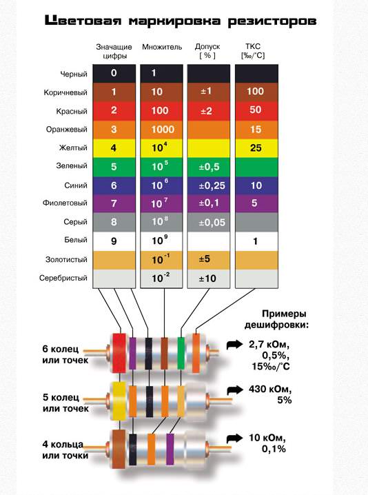
To read resistor markings with colored stripes you can use this table:
The last numbers are used for the decimal multiplier. It should also be remembered that there are six rows of accuracy provided by GOST. For the E6 series, a deviation of 20% is allowed, for E12 - 10%, E24 - 5%, E48 - 2%, E96 - 1%, E 192 - 0.5%.
 Reading stripes is more convenient than markings
 Labeling rules
classical consists of 3-6 strips/rings. The more bars, the more accurate the measurement. Let's analyze the most popular options.
Devices with three stripes
Such marking is used only for those elements that have “planned” deviations of no more than 20%. The numbers relating to colors can be taken from the table above. The first and second circle shows the resistance of the device, the third - the multiplier indicator.
If we designate the first strip D1, the second D2, the third E, then the formula for calculating the resistance will look like this:
R=(10D1+D2)*10E
For example, on the desired resistor, the first strip is red, the second is green, and the third is yellow. We are looking for resistance (10 * 2 + 5) * 104 \u003d 25 * 10 to the 4th power \u003d 250000 Ohm or 250 kOhm.
Devices with 4 strips
Used for devices with an accuracy of up to 5-10% (series E12 and E24 according to GOST marking). Resistance marking scheme by color remains the same: the first two rings are the resistance value, the third is the decimal multiplier, the fourth is the tolerance. Golden tolerance - 5% (refers to the E24 series), silver - 10% (E 12 series). In this case, the formula looks like this: R=(10D1+D2)*10E±S, where the first band is D1, the second is D2, the third is E, and the fourth is S.
Example:if you see a device with 4 bands of green, orange, red and gold, then the resistance will beR \u003d (50 + 3) * 10 of the second degree \u003d 5300 Ohm + -5% or 5.3 kOhm ± 5%.
 Resistors with 4 strips
 Devices with 5 strips
Similar marking of resistors on strips used for bands E48 - 2%, E96 - 1%, E 192 - 0.5%. The technique for counting the first three bands remains the same, the fourth indicates the decimal multiplier, the fifth - the tolerance level. The formula looks like this: R=(100D1+10D2+D3)*10E±S, where D1, D2 and D3 are the first three circles, E is the fourth, S is the fifth. Tolerances are designated as follows:
- E48 (2%) - red;
- E96 (1%) - brown;
- E192 (0.5%) - green;
- 0.25% - blue;
- 0.1% - violet;
- 0.05% - gray.
Six-band devices
Professional repairmen know that some resistors have a so-called thermal resistance coefficient, or TCR for short. This parameter shows by what amount the resistance of the element increases / decreases when the temperature changes by 1 degree. This ratio is measured in ppm/ O C (parts per million or one millionth of the available denomination, divided by the number of degrees). Let's analyze the designation of resistors by color on the sixth ring:
- Brown - 100ppm/ OC.
- Red - 50ppm/OC.
- Yellow - 25 ppm/OC.
- Orange - 15ppm/OC.
- Blue - 10ppm/OC.
- Violet - 5ppm/OC.
- White - 1ppm/OC.
Let's analyze an example of determining a resistor by color coding efor 6 rings. For example, we have a resistor with red, green, purple, yellow, brown and orange stripes. The resistance will be (100*2+10*5+7)*10 4+-1% (15ppm/ O C) or 2570000±1% (15ppm/ O C) or 2.57 ±1% (15ppm/ O C) MΩ.
Attention:the sixth ring is often used to calculate the element's safety factor. If it is a standard width, then it determines the ppm/ O C, if it is one and a half times wider, then it shows the percentage of element failures per one thousand hours of operation.
The colors in this case are as follows:
- Brown - up to 1 percent bounce.
- Red color - no more than 0.1% failures.
- Orange color - no more than 0.01% failures.
- Yellow - no more than 0.001% failures per 1000 hours of operation.
As a worksheet for determining resistance, you can use the following option:
 Table for reading the resistor value
 Wirewound resistors
For wire resistors, a slightly different decoding resistors by color . The first strip in any case will be wide white stripe, which speaks of manufacturing technology (wire). They cannot have more than 4 stripes, the last ring indicates the properties of the microelement. Study our table - it will allow you to figure out how to correctly read the values \u200b\u200bof wire devices.
 Schematic for wirewound resistors
 As you can see, there is nothing complicated in marking - using our two tables you can easily determine the capacity of any denominations. With a little practice and you will remember the key colors, because most of the resistors are made of boundary values are used quite rarely. An experienced craftsman immediately reads the marking and understands how the device works.
The resistor is an element active resistance electric current. Electrical resistances as radio components are given the name of a resistor. This is done in order to distinguish between "resistance" as a product and "resistance" as its electrical property, electrical quantity. Resistors are fixed and variable. Fixed resistors are classified by types, rated power, rated electrical resistance, the largest possible deviation of the actual resistance from the nominal (the amount of deviation from the nominal is also called the tolerance.
In this article, we will talk about fixed resistors. The marking of such resistors is alphanumeric and color. The color marking of resistors is 3.4 or 6 transverse colored bands. The use of color coding has advantages over digital coding. Firstly, resistor color marking is easier to apply to the product, especially for miniature resistors. Secondly, it is easier to implement automatic assembly. The disadvantage of such marking is that when determining the value of the resistor, it is necessary to have at hand a coding table that deciphers the color marking of resistors, or use a measuring device (multimeter, tester, etc.). The next inconvenience of such marking is the difficulty of determining the nominal resistance of a used resistor when repairing any equipment. Indeed, in this case, the color marking of resistors under the influence of temperature and other external factors(moisture, dust), as well as in the event of a burnout of the resistance element, it may be damaged (blacken, fade, change color). Measuring the value of the resistor with the device in this case may not always give the correct result, since the resistance of the resistor could change, or if the resistance element burns out, the device will show a “break”.
The color code values are shown in the photo. 
When reading color markings, you must first find out from which side to start counting the stripes. In resistors made in the USSR, the first strip is always shifted to the edge of the resistor. In modern-style resistors with a marking consisting of four stripes, the last strip is applied in gold or silver, it indicates an accuracy of 5% or 10%, respectively. Resistors with three stripes have an accuracy of 20%. High-precision resistors are marked with 5-6 stripes. In all types of color markings, 1 and 2 stripes indicate the first digits of the element's face value. If the marking consists of three or four stripes, then the third strip means a multiplier. The resulting value must be multiplied by the value encoded in the first two bands. If the color marking of the resistors consists of 5 bands, then the third band also refers to the resistance value, and the fourth in this case will mean a multiplier, the accuracy is encoded in the fifth band. If there is a sixth strip in the marking, then it indicates either the temperature coefficient or the reliability of the element.
 Color coding imported resistors, which are most often found in our country, usually consists of four colored bands. The first 2 bars indicate the value of the resistor, and the third - the multiplier. The fourth band indicates the permissible deviation from the nominal value.
The main purpose resistors– converting current to voltage or performing the reverse process, limiting the current strength, absorption electrical energy. Used in almost all complex electrical diagrams so pay attention to the color coding.
Due to their small size, resistors are rarely marked with a numerical or alphabetic value. Most often, colors are applied, which determine all the basic qualities. In order to choose the right resistor, you should know the features of applying colored dots or lines.
Standard color coding
In order to properly label and tables have been widely used, have been adopted international standards, according to which from 3 to 6 strips can be applied to the resistor, each of which has a specific purpose.
Consider the features of the standard color marking:
- Marking with 3 stripes is carried out as follows: the first 2 rings indicate numbers, 3 - a multiplier. There are no 4 rings, since for all such resistors the accepted deviation is 20%.
- 4 rings- marking, which is somewhat different from the previous case. The last ring means deviation. All values are selected using a special table. In this case, the deviation is 5%, 10%.
- 5 rings means the minimum deviation rate, up to 0.005%. In this case, the first 3 rings mean numbers, which then need to be multiplied by a multiplier. You can find the multiplier using the same table, you need to look for the color value of 4 rings.
- There are versions of resistors that have 6 rings. Their interpretation is carried out in the same way as with 5 rings, only the last of them means the temperature coefficient of change. Given value determines how much the resistance value will change when the temperature of the resistor body rises.
Not all tables have a column for deciphering the 6th ring, which should be taken into account.
What is it for?
Low power resistors are very small size, their power is about 0.125 watts. The diametrical size of this embodiment is about a millimeter, and the length is several millimeters.
Reading the parameters, which often have several numbers, is quite difficult, as well as applying them. When specifying the denomination, if dimensions allow, a letter is often used in order to determine the fractional value of the value.
An example is 4K7, which means 4.7 kOhm. However, this method is also not applicable in some cases.
The marking color scheme has the following features:
- Easy to read.
- Easier to apply.
- Can transfer all the necessary information about the denominations.
- With time information is not deleted.
At the same time, it is possible to note the main difference in this marking:
- With an accuracy of 20% a marking containing 3 strips is used.
- If the accuracy is 10% or 5%, then 4 strips are applied.
- More accurate options executions have 5 or 6 strips.
Summing up, we can say that applying colors allows you to find out the accuracy and nominal values \u200b\u200bof the resistor, for which you need to use special tables or online services.
Online calculators
 The most popular include:
- http://www.chipdip.ru/info/rescalc - a service that allows you to carry out calculations for versions that have 4 or 5 marking strips. The service works as follows: the table has columns that correspond to a particular color band, and rows contain colors. In order to carry out the calculation, it is enough to mark the color in the corresponding line. The calculator in question allows you to calculate the resistance and tolerance, which are measured in MΩ and percent, respectively. The advantage of this online calculator is the presence of not only the name of the color, but also its sample. This feature allows you to quickly make comparisons to perform calculations. Unlike other similar calculators, in this case there is a visual picture that changes when certain colors are selected. That is why, it is very easy to use, as a good example allows you to understand which resistor was chosen for the calculations.
- http://www.radiant.su/rus/articles/?action=show&id=335 - a service that also allows you to quickly calculate the nominal values for the version with 4 bands. This calculator has a simple circuit work: there are 5 fields, when opened, the name of the color and its sample are displayed. After selection, the calculation of the resistance indicator is carried out, which is displayed in ohms, as well as limit deviation in percentages. The service in question has not only a calculator, but also illustrative examples of calculations, tables with the necessary information, and much more.
- http://www.qrz.ru/shareware/contribute/decoder.shtml is one of the few services that allows you to calculate for 3 lines, as well as 4 and 5. Unlike other versions, this one does not have a visual picture of that how one or another version of the resistor looks like when changing the color of the line. Also, it can be said that this option Calculator execution is one of the most difficult. If the resistor has 3 strips, the designations are entered in 1, 2, 4 fields, if 4 - in 1, 2, 4, 5, if 5 - you need to fill in all fields. The result is displayed as a resistance value in KΩ, there is also a field indicating the error as a percentage.
All calculations are carried out exclusively when marking is carried out in accordance with the accepted rules of GOST 175-72. Lines are always read from left to right. It should be noted that according to the accepted rules, the first page is always located closer to the conclusion.
If this cannot be done, the first strip is made wider than the rest. These rules should be taken into account when deciphering the resistor using a calculator.
Universal Color Chart

There is a universal color table that allows you to quickly calculate the values \u200b\u200bof each resistor if necessary.
When creating such a table, the following fields are distinguished:
- The color of the ring or applied dot. At the same time, both the name and an example are given.
- Depending on whether, what is the value of the color, it is possible to translate the color coding into a numeric value. This is necessary when creating a schema for symbol denominations.
- Factor allows you to carry out a mathematical calculation of what resistance the considered embodiment has.
- Also, for almost every color there is a field that indicates the maximum deviation from the nominal value.
It is worth remembering that each color can indicate a number in the marking, the value of the multiplier or the maximum deviation.
Examples

Example 1:
Consider the use of such a table in the following example: brown, black, red, silver. We read the rings from left to right, the resulting value is always encoded in Ohms.
According to the data from the table, we carry out the following decoding:
- Brown color in the first position denotes both a digit and a multiplier. In this case, the number will be "1" and the multiplier "10". It is worth noting that in the first position can not be used following colors: black, golden or white.
- Second color means the number of the second digit. Black means "0" and is not used in calculations. Having such data, we can conclude that the resistor has an alphanumeric marking 1K0.
- third color determines the multiplier. In our case, it is red, the multiplier for this color is "100".
- last color means maximum deviation tolerance, and silver color corresponds to 10%.
Using the table, we can say that the resistor in question is marked 1K0 and has a resistance value of 1000 Ohm (10 * 100) or 1 kOhm, as well as a tolerance of 10%.

Example 2:
One more more complex example let's call the calculation of the nominal values of the following resistor: red, blue, purple, green, brown, brown. This marking consists of 6 rings.
When deciphering, note the following:
- 1 ring, red- the number "2".
- 2nd ring, blue- the number "6".
- 3 ring, purple- the number "7".
- All numbers are selected from the table. When combined, we get the number "267".
- 4 ring has a green color. In this case, we pay attention not to numerical value, and a multiplier. Green color corresponds to a factor of 10 5 . We carry out the calculation: 267 * 10 5 \u003d 2.67 MΩ.
- 5 ring It has Brown color and it corresponds to the value of the maximum deviation in both directions of 1%.
- 6 line brown, which corresponds to a temperature coefficient of 100 ppm/°C.
From the above example, we can say that it is not difficult to decipher the marking, and the number of rings has practically no effect on how difficult the calculations will be. In this case, the resistor has a resistance of 2.67 MΩ with a 1% deviation in both directions at a temperature coefficient of 100 ppm/°C.
The procedure can be simplified by using special calculators. However, not many perform the calculation of 6 rings, which is worth considering.
The nominal series of resistors can be called the result of the standardization of nominal values. Fixed resistors have 6 similar rows. Also, one row for variable denominations and a special row E3 have been introduced.
Using the example of the given denomination, we will decrypt:
- Letter "E" means that marking is carried out according to a number of denominations. This beech always goes in the designation.
- Numbers after letters means the number of nominal resistance values in each decimal interval.
There are special tables with the display of nominal series.
To identify standard series, GOST 2825-67 was adopted. At the same time, several of the most popular standard series can be distinguished:
- Row E6 has a deviation in both directions of 20%.
- Row E 12 has a tolerance of 10%.
- Row E24 has an indicator of the maximum allowable deviation in both directions of 5%.
The subsequent rows E48 and E96, E192 have a deviation rate of 2%, 1%, 0.5%, respectively.
Summary table of color marking resistors

For everyday use, you can use a color coding summary table that combines the following information:
- Color matching certain values.
- Numbers nominal row.
- Value multiplier.
- Value tolerance.
- Index temperature change coefficient.
- Bounce rate.
Such a table will allow you to quickly decipher the marking.
Features of marking wire resistors

The rules adopted for the color marking of resistors apply to all their types, including wire versions.
In this case, there are only a few hallmarks to be taken into account:
- 1 strip, which is wider than others and usually white color, is not part of the marking, but only indicates the type of resistor.
- Decimals more than 4 cannot be used for marking.
- Last strip may indicate special properties, such as fire resistance.
The table that is used in this case is slightly different. The difference lies in the size of the multiplier.
Non-standard marking of imported resistors

Despite the accepted rules for color marking, some companies use their own standards. These include:
- Philips- manufacturer of household and industrial electronics, which introduced some of its standards in the area of \u200b\u200bmarking resistors. So it can be noted that the company uses colors not only to indicate the main characteristics, but also to display the production technology and the properties of the components. To do this, the body itself is painted in a certain color, and the rings are arranged in a certain order relative to each other.
- CGW and Panasonic also introduced their own labeling rules. So these manufacturers carry out the application of information about the special properties of the resistor.
Almost all manufacturers in the world have adopted the established rules, which makes it possible to simplify the procedure for identifying denominations.
In conclusion, we note that in addition to color marking, alphanumeric designations may be present. They are applied to the surface of fairly large resistor designs and can also be used to test performance.
Elements are called resistors. electrical circuit with their own resistance. In practice, a rare scheme can do without their use. Resistors are classified by accuracy class, by power, by nominal resistance and other parameters.
Description
The resistors are very small, a few millimeters, which greatly complicates the location of a readable marking. For this reason, an international color marking system for electrical components has been adopted. According to generally accepted requirements, the marking should be located on the body of fixed resistors in the form of multi-colored stripes or rings. This way of designation provides readability in any direction. The starting strip of the marking is located closest to the edge of the element. In situations where the features of the case or other reasons make it difficult to mark in this way, the first ring is indicated by a line twice as wide.
The marking should be read from the leftmost lane to the right. If it cannot be found, the resistance corresponding to the standard nominal series is taken as true (that is, we read the other way around if it does not work out).
Rating table
The color marking and reading of resistors is based on a universal table of values of the nominal range and their corresponding colors.
It is called universal due to the fact that it can be equally effectively used for reading not only the face value, but also the multiplier (decimal value). Numerical values-2 and -1 are assigned for the convenience of working with decimal powers.
Standard marking
Any types of fixed resistors are color-coded with 3 to 6 colored stripes. Let's take a look at all below possible options rings.
With 3 rings
This system is used with respect to fixed resistors, characterized by a tolerance of ± 20% (nominal series E6, that is, for each multiplier there are only six different values resistance values). Colors have values corresponding to the main table. The first two bands mark resistance, and the last one marks the decimal value. 
According to the scheme for calculating the resistance of a resistor, the formula is used: R = (10D1 + D2)*10^E. Looking at the table, we see that the resistance value of the resistor from the figure (Red, Red, Green) is R = (20+2)*10^5 = 2200000 = 2.2MOm ±20%.
With 4 rings
This color marking of resistors is intended for elements from the nominal series E24 (5%) and E12 (10%). In this system, the first two bars represent the resistance, and the next one represents the decimal multiplier. The fourth bar shows the resistance tolerance: gold - ± 5%, silver - ± 10%.

Formula for calculating resistance: R = (10D1 + D2)*10^E ± S. Thus, for the resistor shown in the figure (Green, Brown, Red, Gold) R \u003d (10 * 5 + 1) * 10 ^ 2 \u003d 5100 will be equal to 5.1KOm ± 5%.
With 5 rings
This marking system is designed to designate resistors with tolerances up to 5%. The principle of reading is the same: the first three lines indicate the face value, and the fourth and fifth - the decimal multiplier and tolerance.

The formula corresponding to this system. Formula: R=(100D1+10D2+D3)*10^E ± S.
For resistors in series E48, E96 and E192, an additional table of precision resistors is used.
Thus, the resistance value of the resistor shown in the figure (Red, Blue, Blue, Brown, Green) is R \u003d (200 + 60 + 6) * 10 \u003d 2660 \u003d 2.66 KOm ± 0.5%.
With 6 rings
In addition to the above indicators, colored stripes can also indicate the temperature coefficient of resistance. This indicator shows the largest change in the resistance of the resistor when heated or cooled by 1˚C. Its value in the marking is measured in millionths of a nominal value per degree - ppm / OC. The correspondence of the temperature coefficient and colors is presented in the table:
The figure below shows a 6-band color-coded resistor. In this case, each ring has the same function as in the 5-strip example. The last bar is used to indicate the value of the TCR. 
R = (100D1 + 10D2 + D3)*10^E ± S (Appm/˚C)
After decoding according to the available tables, we obtain the following value of the resistance of the resistor:
R = (500+7+2)*10 = 5.72 KOm ± 1% (10 ppm/˚C)
Sometimes the sixth ring is used to indicate the reliability of the resistor, when its width is at least 1.5 times greater than all the others. This indicator is measured as a percentage and means the number of element failures per 1000 working hours. Reliability standards are also indicated by color rings, according to the following table:
General table
If necessary permanent use listed tables, it is much more convenient to have a summary table of the correspondence of colors and indicators of face value, decimal multiplier, tolerances and temperature coefficient. (The tolerance value changes for some reason inconsistently - 1, 2, 0.5, 0.25,0.1, 0.05)
| Ring color | 1 ring | 2. ring | 3 ring | 4 ring | 5 ring | 6 how many | |
| Numbers of the nominal series | Tolerance | TKS, ppm/˚C | Bounce rate | ||||
| 1 | 2 | 3 | |||||
| Black | 0 | 0 | 0 | 0 (1) | |||
| Brown | 1 | 1 | 1 | 1 (10) | ±1% | 100 | 1% |
| Red | 2 | 2 | 2 | 2 (100) | ±2% | 50 | 0,01% |
| Orange | 3 | 3 | 3 | 3 (1000) | 15 | 0,01% | |
| Yellow | 4 | 4 | 4 | 4 (10^4 ) | 25 | 0 ,001% | |
| Green | 5 | 5 | 5 | 5 (10^5) | ±0.5% | ||
| Blue | 6 | 6 | 6 | 6 (10^6) | ±0.25% | 10 | |
| Violet | 7 | 7 | 7 | 7 (10^7) | ±0.1% | 5 | |
| Grey | 8 | 8 | 8 | 8 (10^8) | ±0.05% | ||
| White | 9 | 9 | 9 | 9 (10^9) | 1 | ||
| Silver | -2 (0,01) | ±10% | |||||
| Gold | -1 (0,1) | ±5% | |||||
The marking rules specified here correspond to almost all non-wire resistors with pigtails.
Wirewound resistors
The requirements for color marking wirewound resistors are not much different from the above requirements for their counterparts of a different type. However, there are several differences:
- a large white stripe located at the beginning does not indicate the rating, but indicates the wire type of the resistor;
- decimal multipliers above the 4th degree are not used for marking wire parts;
- a colored bar at the end of the marking sometimes indicates the properties (for example, heat resistance or fire resistance) of the resistor, and not the TCR value.
In addition, wirewound resistors differ slightly in tolerance. The following summary table shows the tolerance values and color code values for wirewound resistors.
| Ring color | Row denomination numbers | Decimal (factor) |
Tolerance | ||
| 1 | 2 | ||||
| Black | 0 | 0 | 0 (1) | ||
| Brown | 1 | 1 | 1 (10) | ±1% | |
| Red | 2 | 2 | 2 (100) | ±2% | |
| Orange | 3 | 3 | 3 (1000) | ±3% | |
| Yellow | 4 | 4 | 4 (10000) | ±4% | |
| Green | 5 | 5 | |||
| Blue | 6 | 6 | |||
| Violet | 7 | 7 | |||
| Grey | 8 | 8 | |||
| White | 9 | 9 | |||
| Silver | -2 (0,01) | ±10% | |||
| Gold | -1 (0,1) | ±5% | |||
It is worth noting that some manufacturers of imported resistors adhere to their own color marking system. So, for example, at Phillips, in addition to the color of the stripes, the color of the case, as well as the location of the stripes relative to each other, matters. These features can talk about the properties and manufacturing technology of the element. Panasonic and CGW use leading and trailing rings for marking in addition to color distinctive properties element and technology.
Other marking systems
On old Soviet resistors, a different, simpler marking was used - they simply had a resistance indicator written on them. The letters of the Latin alphabet were used to indicate the decimal degree of digits. R is the first power, K is the third (thousands), M is the fourth (millions). For example, digital marking 2M5 means that the resistor value is 2500 KOm, and 1K7 means 1700 Ohm. This method is very simple and allows you to instantly calculate the resistance without the use of additional tables. The only drawback could be fixing the resistor on the board in a position where the inscription was at the bottom, and it became impossible to read. This turned into a significant problem when it was necessary to save space on the board, as, for example, in Japanese technology those years. Therefore, such a labeling system has not taken root in other countries of the world.
With development electronic technology it became impossible to solder resistors to the boards through special holes. It took up too much space, and the general trend of miniaturization of technology dictated its conditions. This is how a new method of mounting microcircuits appeared - SMD (surface mount technology), where circuit elements are soldered to the track itself without legs and holes. The marking of resistors, diodes, capacitors, other components of microboards and chips required the definition of a new system.
Marking SMD resistor ov is somewhat similar to the Soviet method - it also uses symbolic-letter designations, but, of course, with its own arrangement rules. Here, for example, it is not always required to put a letter, and R is used as a separating comma in some situations. SMD encoding is divided into three types:
- Codes with 3 digits. The first 2 indicate the denomination in Ohms, and the last decimal power of the number (“182” would mean 18 * 100 = 1800 Om).
- Codes with 4 digits. Here the resistance is indicated in the same way as in the 3-digit marking, but with 3 digits of the nominal value (“4502” means 450 * 100 = 45 KOm).
- Codes of 3 characters. In these codes, the first two digits indicate the denomination, and the letter following them indicates the number of zeros (decimal power). The following symbols are used: F = 10^5, E = 10^4, D = 10^3, C = 10^2, B = 10, R=10^-1, S=10^-2. So, for example, an SMD resistor marked 14D has a rating of 14 KOm.
The need to use color marking of radio components is associated with their small dimensions. For example, a CF type resistor (domestic analogue C1-4) with a power of 0.125 W or 0.25 W (Mini version) has a length of 3.2 and a diameter of 1.8 mm. It is impossible to read the marking on such a device.
The rules for applying the color marking of resistors are regulated by the requirements of GOST 175-72 and Publication 62 of the International Electrotechnical Commission (IEC, IEC). In accordance with the rules, color marking in the form of rings is applied to the cases of fixed resistors with wire leads. This type of marking allows you to confidently read the values in any position.
The first colored ring is shifted towards one of the pins. In the case when the dimensions of the case or other reasons do not allow such an arrangement, an increased (twice) width is used to designate the first strip. The stripes are read, starting from the first, from left to right.
If it is still not possible to determine the first mark, the resistance, which showed compliance with the standard series, is taken as the true value.
The color marking of resistors is based on a universal table in which each of the colors uniquely corresponds to a number.
This lookup table is used to read the denomination and decimal digits. For the convenience of encoding resistances, the numbers -1 and -2 for the decimal multiplier are entered in the table.
Standard series of denominations
When determining the resistance of a resistor, it must be remembered that the value can correspond to one of the six standard rows according to GOST 2825-67. Each of them is designed for a certain tolerance at par.
- Series E6, tolerance ±20%
- Series E12, tolerance ±10%
- Series E24, tolerance ±5%
10; 15;22; 33; 47; 68.
10; 12; 15; 18; 22; 27; 33; 39; 47; 56; 68; 82.
(10;11; 12; 13;15;16;18); (20;22;24;27); (30;33;36;39); (43;47); (51;56); (62; 68); 75; 82; 9.1.
For series E48, E96, and E192, the maximum tolerance is ±2%, ±1% and ±0.5% respectively
The ratings in the rows are calculated taking into account the overlap due to the deviation, the difference between adjacent positions is less than twice the tolerance. The denominations of each of the rows correspond to members of a geometric progression with an exponent of 10 1/k, where k is the characteristic number of the row (for E12 k=12, for E48 k=48, etc.)
Multiple resistances can be obtained by multiplying the given values by powers of 10.
Series with small tolerances are characterized by the presence of three significant figures in the resistance values, which determines some features of color marking.
Standard color coding for resistors
For all types of fixed resistors with flexible leads, marking systems with 3, 4, 5, and 6 colored rings are used.
Color coded with 3 stripes

This marking system is used only for resistors with a tolerance of ±20%. The colors of the stripes correspond to the universal table above. The first two bands mark the resistance, the third band indicates the decimal multiplier.
In accordance with the notation shown in the figure, the resistance of the resistor is determined as follows
R = (10D1 + D2) * 10E
The principle of operation of the triac allows you to use feedback. This action can be compared with the work of the door in the subway. It is this feature that explains the widespread use of various schemes regulation.
Before embarking on the manufacture of the simplest switching power supply, you need to familiarize yourself with its circuit diagrams. Practical recommendations by choosing the main elements for assembly, you can study.
For the resistor shown, the resistance value is:
D1 (red ring) = 2
D2 (red ring) = 2
E (green ring) = 5
R \u003d (20 + 2) * 105 \u003d 2200000 Ohm \u003d 2.2 Mohm
Marking with 4 colored rings

This marking system is used for resistors of nominal series E12 and E24. As in the case of encoding with three rings, the first two are used to indicate the denomination, the third - the value of the decimal multiplier. The fourth color ring represents the resistance tolerance. For series E12 and E24, only two colors of the last band are used, silver for ±10% tolerance marking (E12) and gold for ±5% tolerance marking (E24).
R = (10D1 + D2) * 10E±S
The value of the resistor shown in the figure:
R \u003d (50 + 1) * 102 \u003d 5100 Ohm \u003d 5.1Kom ± 5%.
Color marking with 5 stripes

To mark resistors with tolerances of less than 5%, the denomination of which contains 3 significant digits, 5 colored stripes are applied to the case. The principle of reading the resistance remains unchanged - the first 3 bands indicate the numbers of the nominal series, the fourth - the value of the decimal multiplier, the fifth - the tolerance.
R = (100D1 + 10D2 + D3) * 10E±S
Tolerance color codes for nominal series E48 (±2%), E96 (±1%) and E192 (±0.5%), as well as precision resistors are summarized in the table: 
Using the universal color chart and table color coding tolerances gives the following decoding of the marking of the resistor shown in the figure:
R = (200+50+5)*101 = 255*10 = 2550 Ohm = 2.55kOhm ± 0.5%
Use of 6 color rings for marking resistors
In addition to the rating and tolerance in the color marking of resistors, such important parameter like tks.
TCR - temperature coefficient of resistance, shows the maximum value by which the resistance of the resistor can change when the temperature changes by 1 degree.
For marking on the body, the TCR value is shown in ppm/OC. The ppm value (abbreviation parts per million) reflects the millionths of the resistor value.
 For organizing home lighting, the most popular switch option has become a two-gang switch. This is due to its wide range of applications and high level saving resources, both material and energy. To do it right, you don’t need special knowledge, it’s enough to prepare well and adhere to the installation scheme.
Microwave is the most common household electrical appliance in every house. In the event of breakdowns, it is not at all necessary to carry it in service center, but it is quite possible to do it at home, having previously studied the device and the microwave oven.
The table of correspondence between the colors of the marking rings and the TKS values is given below. 
An example of color coded resistors using six rings is shown below. When using such a notation, reading the denomination and tolerance is no different from the case of a five-digit color marking. The sixth bar shows the TCR of the resistor. 
R = (100D1 + 10D2 + D3) * 10E ± S (Appm/OC)
Deciphering the designation for the resistor shown in the figure gives the following results:
R= (500+6+2)*101 = 5620Ω = 5.62kΩ ± 1% (10ppm/OC)
The sixth color marking ring can be used to display information about the reliability of the resistor. In this case, the width of the sixth ring should exceed all the others by 1.5 times. The reliability indicator is considered as the percentage of element failures per 1000 hours of operation. The normalized reliability values and their color designations are presented in the following table 
Summary table of color marking resistors
For daily use as a handy material for working with the color marking of resistors, it is convenient to bring disparate tables for reading the numbers of the nominal series, decimal index, tolerances and TKS into a single one. 
The above labeling rules are valid for most non-wire resistors with flexible leads.
Features of marking wire resistors

The color marking of wirewound resistors is subject to the same requirements and rules as the designation system for fixed resistors based on other technologies. The difference in labeling is as follows:
- the first wide white stripe is not included in the denomination marking, but indicates the manufacturing technology - a wire resistor;
- decimals greater than 4 are not used;
- the last colored bar may indicate special properties of the resistor (for example, its fire resistance).
There are also differences in the tolerances of wirewound resistors from resistors of other technologies.
A summary table of color display of ratings and tolerances of wirewound resistors is presented below. 
Non-standard color marking of imported resistors
Some companies have their own rules for color-coding resistors in addition to the standards set by IEC Publication 62.
- Company Phillips uses color for more than just marking the basic characteristics of resistors. Resistor body color mutual arrangement the marking strips carry information about the technology and the special properties of the components.
- Markings of manufacturers such as CGW (CorningGlassWork) And Panasonic contains, in addition to colored rings indicating resistor parameters, leading and/or trailing bands containing information about the technology and special properties of resistors.
In general, color marking standards are met by all the world's leading manufacturers. electronic components. This greatly simplifies the identification of ratings and basic parameters of resistors with pigtails and work as industrial manufacturer electronic equipment, and a radio amateur.
Video on how you can use the color marking of resistors
 (1 ratings, on average: 5,00 out of 5)

