Color designations for PE and N busbar insulators, purpose and definition of busbars, as well as connection diagrams for PE and N busbars. Color marking of grounding conductors
Grounding is a topic that is as complex as it is simple. No wonder this grounding issue causes a lot of controversy on electrical sites and forums.
Let's try to figure out what's what in this topic. I will express my opinion, which sometimes will be unpopular. Who needs an official interpretation - read the PUE (clause 1.7). There are also many sites and forums on the Internet where the issue of grounding is described in detail.
The essence of grounding
Why do you need grounding if everything works fine without it? Moreover, in normal mode via wire protective grounding no current flows at all.
The key word here is “protective.” Who does grounding protect and from what? It protects human bodies from the effects of electric current. And what it protects against is to ensure that dangerous voltage does not appear on the human body under any circumstances, and that current does not flow through the person.
Let's imagine the situation. There is a certain electrical appliance, for example an iron. The iron is connected through this plug.

Older readers remember these very well, they were constantly unwinding, and to attach to them flexible wire it was torture.
The body of the iron is partially metal. What happens if a phase suddenly gets on the body? In principle, nothing, the iron can even continue to work. But its body will be at a potential of 220V relative to ground. And since we all walk on the earth, if we touch the metal body of such an iron, current will flow through us.
But if the body of the iron is grounded, then when the phase wire hits the body, it will connect to the ground and go into the ground. In this case, an actual short circuit will occur and the circuit breaker of this line will be knocked out. And the body will remain as it was at zero potential.
In other words, if a phase suddenly gets onto the body of the device, this is no longer a human problem. This is a problem with the device itself and the circuit breaker, which must disconnect this device from the phase wire.
Why does the circuit breaker turn off? If the phase wire touches the protective (grounding) conductor, this is equivalent to a short circuit, that is, the maximum possible current in the circuit. And the machine will work due to electromagnetic protection.
That is, the current in the protective grounding wire flows only at the moment of an accident, the rest of the time it is useless. Therefore, they used to save on it and use a two-wire power system, in which there is only zero and phase.
Designations and translation of names of grounding systems
There are TN, TT and IT grounding systems. The TN system, in turn, is used in three various options: TN-C, TN-S, TN-C-S. The first letter indicates the method of grounding the source electrical energy(generator or transformer), the second - consumer.

These letters come from French and mean: “Terre” - earth, “Neuter” - neutral, “Isole” - isolate, and also from English: “Combined” and “Separated” - combined and separate.
- T - wire connected to ground.
- N - connection to neutral.
- I - isolation.
- C - combining functions, connecting the working and protective neutral wires.
- S - separate use of working and protective neutral wires throughout the entire network.
The following designations are also used in grounding system diagrams:
- L - Line, The line on which the phase voltage operates in relation to the neutral wire.
- N - Neutral, a working zero through which a working current flows equal to the current in the wire L (for single-phase systems).
- PE - Protect Earth, protective earth, protective ground wire.
- PEN is a combined working and protective neutral conductor.
Brief description of the operation of grounding systems
Grounding systems are primarily characterized by safety. That is, how many chances to survive does such a system give a person after a phase appears on the body.
There is confusion in terminology - I call the same system both grounding and grounding. Wikipedia suggests calling TN systems grounding on the grounds that in them the grounding conductor PEN is connected to the zero (neutral) wire of the power source. And this wire in the transformer is already grounded. Grounded to prevent phase imbalance.
Read more about phase imbalance, why it is dangerous, and how to deal with it -.
PUE, the Electrician's Bible, talks about the same thing as grounding systems.
The difference between these concepts, in my opinion, is very vague. In my opinion, grounding is necessary to maintain the voltage at ground potential on the PE wire and on all non-current-carrying parts of the electrical installation to which it is connected. And grounding is needed to create current short circuit when a phase is shorted on the same parts of the electrical installation. As a result, there can be only one effect - grounded or neutralized parts will never be under phase voltage, and the circuit breaker should operate. This is short and in your own words.
In general, grounding is a broader concept than grounding.
We can say that the protection system is as safe as this point is close to the voltage source. And again, what can be considered a consumer - an electric kettle, an apartment, multi-storey building, or area of the city?
Well, if the phase “breaks through” onto the body, it should be destroyed by the protective circuit breaker with 100% probability.
I think two things are important here:
- All metal that is out of phase must be at the same potential. And it is desirable that this potential be equal to the potential of the earth. This is the “zero” potential.
- Dangerous - inaccessible. Accessible - safe. It happens that you look at the Soviet apartment shields or RP and your hair moves.
And again, I will repeat again. The probability of a break in the neutral working conductor is always considered. The fact is that with such a break, phase voltage is present throughout the entire circuit of the device, up to the zero break point. In the event of a touch, the current passes through the load and through the human body. Despite the load resistance, this current remains as dangerous as when touching a phase wire. After all, the load resistance (for example, an electrical household appliance) is always much less than the resistance of the human body.
Grounding system diagrams
TN-C system
TN-C- the old, Soviet system, when the land was simply taken from scratch directly in the electrical installation itself.
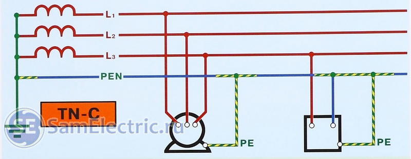
What do we see in this diagram? First and most important. The neutral point of the generator or transformer is connected to ground (solidly grounded). Therefore, the neutral point of the transformer is at ground potential. And since a person also has earth potential, there is a zero potential difference between the body and the neutral conductor, and touching it is safe.
However, not all so simple. I repeat that due to phase imbalance, as well as a voltage drop on the PEN wire, a voltage other than zero may be present on it. Therefore, the PEN wire is forcibly “pulled” to ground potential at certain intervals along the line.
The Earth (what our planet is made of) is a universal and absolute zero in potential. But if a person is given the potential of a phase wire, then touching the ground will be fatal. At the same time, touching a wire with the same potential will be safe.
I saw a documentary about a man calmly descending from a helicopter onto a high-voltage line and working there.
In general, everything is relative. You can fall from a 5-story building to your death. Or you might not get hurt at all if you fall from the same house. From the first step of the first floor)
The TN-C system is now officially banned, and can only be used in three-phase systems, where there is no phase imbalance, and current does not flow through the PEN conductor (zero, also known as protective) in normal mode. As a result, there will be a zero potential on this wire (and therefore on the body of the device).
However, in old housing stock it is used everywhere because of its low cost. The low cost of the TN-C system is its only advantage. After all, the cross-section of the protective conductor PE is single-phase network must be equal to the cross-section of the phase wire. And this means an increase in the cost of all electrical wiring by at least a third.
Generally speaking, there is no grounding at all in this system, and I don’t quite understand why “it” is called a grounding system. Perhaps you can throw a zero on the body, and the device will be “sort of” grounded.
Even before, when all the wiring was done using this system, there were practically no household appliances that required grounding.
The first “swallows” were washing machines, which were electrocuted. In the best case, they pulled a wire from the body of the access panel to them, in the worst case, they hooked the body of the car to a water pipe or to the neutral wire.
The desired effect, of course, is achieved, but the chances of falling under phase voltage increase significantly. The main danger comes from the possibility of a break neutral wire, and then all “zeroed” devices, and also devices with switching power supplies, will receive phase potential on their cases.
How to protect yourself from defeat electric shock in the TN-C system? Here I remember the RCD (Residual Current Device). Let's imagine - a person touched a phase wire. The current bifurcates - part (hopefully, a larger part) goes into the neutral conductor, and part - through the human body to the body. There is a differential difference (sorry, tautology) in the currents in phase and zero, which should trigger the RCD.
However, the PUE directly says - in the TN-C system the use of RCDs is prohibited. Why?
The reason is that in this case, what I wrote about above can happen. RCD is switching device, in which for some reason the PEN-conductor contact may be broken, and the entire consumer will come under phase voltage. Including the housings, if they are grounded, and this is how “grounding” is done in the TN-C system.
PUE also says that the protective conductor (in this case PEN) must not be broken under any circumstances, and must always be connected to a grounded device.
Therefore, RCDs can (and should!) be used in all systems, except TN-C.
Here's a good picture to illustrate the situation:

RCD - application in various systems grounding
I scared you so much that the question will arise anyway: how to live with this now?
I answer. To avoid this “bad” system, the PEN conductor is divided into N and PE. Moreover, this must be done as far as possible from the consumer, and as close as possible to the voltage source.
So we'll move on to much more safer system - TN-C-S, which I will talk about below.
In practice, the combined PEN conductor is grounded (re-grounded) at the entrance to the building, and there it is divided into neutral N and protective PE, which should not be connected ANYWHERE further.
Another variant - transition to the TT system, in which the protective conductor PE is made on the basis of the ground loop, and is not connected anywhere to the incoming PEN. In this case, PEN becomes N because protective current Under no circumstances will there be any flow through it.
Grounding in an apartment with TN-C wiring
In apartments it is more difficult to separate zero and land. There are always heated debates among electricians about this.
I think there are two viable options here.
1. Leave the zero as is, and take the PE wire from the main PEN conductor. Let it not be from the conductor itself, but from the place where it is connected to the body of the floor panel. The main thing is that our N and PE are connected at different points. PE - on the body, N - on a bus isolated from the body, to which zero comes after the input switch or machine (if any) and the meter. By the way, this is what they did in Soviet times when connecting electric furnaces in apartments.
2. Conduct a three-wire system (L, N, PE), but do not connect PE anywhere. As a result, we do not make changes to the floor panel (by the way, this is prohibited!), and all non-current-carrying parts of electrical appliances, metal structures, pipes, etc. we connect to this conductor. And within the apartment we have grace! Just an important note - groups of sockets must have RCDs in place in case a phase hits the housing within the apartment.
That's it, now let's quickly go through other systems, everything is simpler there.
TN-S system
The third letter in the name is S. This means that the conductors N and PE are separated (Separated) along the entire length from the substation to the consumer.

This grounding system is the safest and most preferred, but is used only in the newest electrical installations. Well, mostly in reality they now use the TN-C-S system. That is old system they try to bring it closer to the new one, moving the connection point N and PE away from the consumer and closer to the power source.
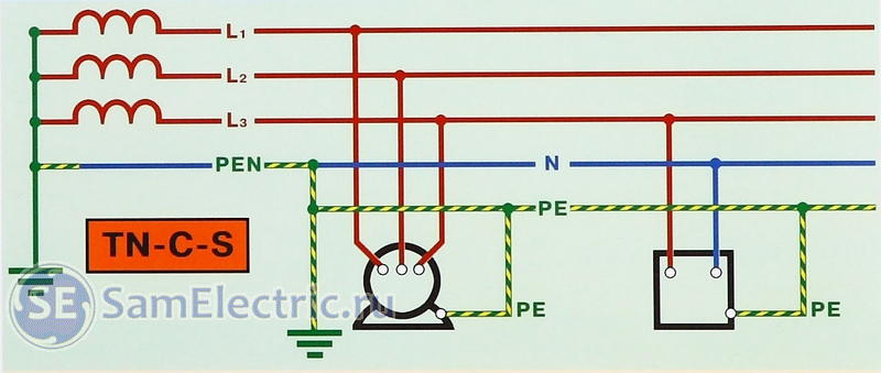
System TN-C-S
The last letters in the name mean that the N and PE conductors after the substation are connected (Connected) into one PEN wire, and then, at the entrance to the building, they are separated.
When a phase hits the housing, the short-circuit circuit breaker should trip. When touching live parts, the RCD should trip.
TT system
Terra - Terra. I already wrote in an article about this system, in which the PE grounding wire is connected to the grounding loop, and nowhere else. It is mainly used in private homes and temporary buildings and electrical installations.

Everything is great if RCDs against touching live parts and circuit breakers against short circuits are also used.
But there is one minus. If in other systems it is not necessary to do your own grounding, relying on grounding at the substation or on poles, then in this case it will have to be done. And do it very well, so that in the event of a short circuit to ground, the short circuit current is sufficient to trigger the circuit breaker.
That is, it is possible that during a short circuit to the case the potential of the case will remain close to zero, everything is fine. But at the same time, the circuit breaker will not knock out, although a current close to the maximum will flow through it (and through the wiring of the house)! And the problem can creep up from the other side...
IT system
Finally, I’ll tell you about the specific IT grounding system. All other systems use power supplies (transformers) with solidly grounded neutral. In other words, the neutral conductor on the source side is grounded.
However, in an IT system, the power source is completely isolated from the ground - both zero and (naturally)) phase.
As a result, there is no potential in relation to the ground. And if there is a short circuit to ground, nothing will happen, because the current will not flow, or will be negligible.
I have seen such systems for powering control circuits in serious industrial equipment. This system is also used in portable generators and other power sources, as well as in medical institutions. If one of the terminals of such a source is not grounded and connected to the load, it will operate according to the IT system.
The downside of such a system is that if it is shorted to ground, it will turn into a TN-C-S with poor installation, and you may not even know about it if you don’t check it. And it will become dangerous.
This concludes the topic, thank you for your patience, I look forward to your opinions and questions in the comments.
Warning: The article is purely informative and does not constitute normative document. When performing work related to electricity, you should be guided by the Electrical Installation Rules (PUE).
Definitions
Grounding- This intentional connection non-current-carrying elements of equipment that, as a result of an insulation breakdown, may be energized, connected to the ground. Grounding consists of a ground electrode (a conductive part or a set of interconnected conductive parts that are in electrical contact with the ground directly or through an intermediate conducting medium) and a grounding conductor connecting the grounded device to the ground electrode.
The ground electrode can be a simple metal rod (most often steel, less often copper) or a complex set of specially shaped elements. The quality of grounding is determined by the value electrical resistance grounding circuit, which can be reduced by increasing the contact area or the conductivity of the medium - using many rods, increasing the salt content in the ground, etc. As a rule, the electrical grounding resistance is standardized.
Main ground terminal. To minimize electromagnetic interference and ensure electrical safety, grounding should be done with a minimum number of closed loops. Ensuring this condition is possible by performing the so-called main ground clamp (MGZ), or bus. The main ground terminal should be located as close as possible to the input power and communications cables and connected to the grounding terminal(s) with the shortest possible length of conductor.
This location of the gas protection zone ensures best alignment potentials and limits the induced voltage from industrial interference, lightning and switching overvoltages coming from outside through the screens of communication cables, armor power cables, pipelines and antenna inputs. The following must be connected to the GZZ (bus):
- grounding conductors;
- protective conductors;
- conductors of the main potential equalization system;
- working grounding conductors (if necessary).
Protective and operational (technological, logical, etc.) grounding conductors, lightning protection grounding conductors, etc. must be connected to the main grounding terminal (bus). The rules and requirements for the GZZ device are set out in detail in the PUE.
Exposed conductive part- a conductive part of an electrical installation that is accessible to touch, not normally energized, but which may become energized if the main insulation is damaged. Exposed conductive parts include metal housings of electrical equipment.
Live part- an electrically conductive part of an electrical installation that is under operating voltage during its operation.
Indirect touch- electrical contact of people and animals with exposed conductive parts that become energized when the insulation is damaged. That is, this is touching the metal casing of electrical equipment when the insulation on the casing breaks down.
Designations
Protective grounding conductors in all electrical installations, as well as neutral protective conductors in electrical installations with voltages up to 1 kV with a solidly grounded neutral, including busbars, must have letter designation RE And color designation alternating longitudinal or transverse stripes of the same width (for tires from 15 to 100 mm ) yellow and green colors. Zero working (neutral) conductors are designated by the letter N And blue. Combined neutral protective and neutral working conductors must have a letter designation PEN and color designation: blue along the entire length and yellow-green stripes at the ends.
Graphic symbols used to indicate conductors on diagrams:

Grounding designation:
Letter designations of the grounding system
The first letter in the designation of the grounding system determines the nature of the grounding of the power source:
T- direct connection of the neutral of the power source to the ground;
I- all live parts are isolated from the ground.
The second letter determines the nature of grounding of exposed conductive parts of the building's electrical installation:
T- direct connection of open conductive parts of the electrical installation of the building with the ground, regardless of the nature of the connection of the power source with the ground;
N- direct connection of open conductive parts of the building's electrical installation with the grounding point of the power source.
The letters following N through a dash determine the nature of this connection - the functional method of constructing the zero protective and zero working conductors:
S- the functions of zero protective PE and zero working N conductors are provided by separate conductors;
C- the functions of the neutral protective and neutral working conductors are provided by one common conductor PEN.
Errors in the grounding device
Incorrect PE conductors
Sometimes used as a grounding conductor water pipes or heating pipes, but they cannot be used as a grounding conductor. There may be non-conductive inserts in the water supply (for example, plastic pipes), electrical contact between pipes may be broken due to corrosion, and finally part of the pipeline may be dismantled for repair.

Combining the working zero and PE conductor
Another common violation is the combination of the working zero and the PE conductor beyond the point of their separation (if there is one) along the energy distribution. Such a violation can lead to the appearance of quite significant currents along the PE conductor (which should not be current-carrying in in good condition), as well as false positives devices protective shutdown(if installed).
Incorrect separation of the PEN conductor
It is extremely dangerous next way“creating” a PE conductor: a working neutral conductor is determined directly in the socket and a jumper is placed between it and the PE contact of the socket. Thus, the PE conductor of the load connected to this socket is connected to the working zero.
The danger of this scheme is that a phase potential will appear on the grounding contact of the socket, and, consequently, on the body of the connected device, when any of following conditions:
- Break (disconnection, burnout, etc.) of the neutral conductor in the area between the socket and the shield (and also further, up to the grounding point of the PEN conductor);
- Rearranging the phase and neutral (phase instead of neutral and vice versa) conductors going to this outlet.

Protective function of earthing
Principle of protective action
Protective action grounding is based on two principles:
- Reducing to a safe value the potential difference between a grounded conductive object and other conductive objects that have natural grounding.
- Discharge of leakage current when a grounded conductive object comes into contact with a phase wire. In a properly designed system, the appearance of leakage current leads to the immediate operation of protective devices (residual current devices - RCDs).
Thus, grounding is most effective only in combination with the use of an RCD. In this case, with most insulation failures, the potential is grounded objects will not exceed dangerous values. Moreover, the faulty section of the network will be disconnected within a very short time (tenths to hundredths of a second - the response time of the RCD).
Grounding operation in case of electrical equipment faults
A typical case of electrical equipment malfunction is when phase voltage enters the metal case device due to insulation failure. It should be noted that modern electrical appliances that have a pulsed secondary power supply and are equipped with a three-pole plug (such as a PC system unit), in the absence of grounding, have a dangerous potential on the case, even when they are fully operational.
Depending on what protective measures are implemented, the following options are possible:
- The housing is not grounded, there is no RCD (the most dangerous option ) . The body of the device will be under phase potential and this will not be detected in any way. Touching such a faulty device can be fatal.
- The housing is grounded, there is no RCD. If the leakage current along the phase-body-grounding circuit is large enough (exceeds the operating threshold of the fuse protecting this circuit), then the fuse will trip and turn off the circuit. The highest effective voltage (relative to ground) on a grounded case will be Umax=RG.IF, where RG is the resistance of the ground electrode, IF is the current at which the fuse protecting this circuit is triggered. This option is not safe enough, since with high grounding resistance and large fuse ratings, the potential on the grounded conductor can reach quite significant values. For example, with a ground resistance of 4 ohms and a fuse rated at 25 A, the potential can reach 100 volts.
- The housing is not grounded, an RCD is installed. The body of the device will be at phase potential and this will not be detected until there is a path for the leakage current to pass. In the worst case, a leak will occur through the body of a person who touches both a faulty device and a naturally grounded object. The RCD disconnects the faulty section of the network as soon as a leak occurs. A person will receive only a short-term electric shock (0.01÷0.3 seconds - the RCD response time), which, as a rule, does not cause harm to health.
- The housing is grounded, the RCD is installed. This is the safest option, since the two protective measures complement each other. When phase voltage hits a grounded conductor, current flows from the phase conductor through the insulation fault into the grounding conductor and further into the ground. The RCD immediately detects this leak, even if it is very insignificant (usually the sensitivity threshold of the RCD is 10 mA or 30 mA), and quickly (0.01÷0.3 seconds) disconnects the section of the network with the fault. In addition, if the leakage current is large enough (exceeds the tripping threshold of the fuse protecting that circuit), then the fuse may also trip. Which one exactly? protective device(RCD or fuse) will turn off the circuit - depends on their speed and leakage current. It is also possible for both devices to be triggered.

Types of grounding systems
In Russia, grounding requirements and its arrangement are regulated by the Electrical Installation Rules (PUE).
The classification of types of grounding systems is given as the main characteristics of the supply electrical network. GOST R 50571.2 considers the following grounding systems: TN-C, TN-S, TN-C-S, TT, IT.

TN system
The neutral of the source is solidly grounded, the electrical equipment housings are connected to neutral wire. TN mode can be of three types: TN-C, TN-S, TN-C-S.
TN-C system
The TN-C system (French Terre-Neutre-Combine) was proposed by the German concern AEG (AEG, Allgemeine Elektricitäts-Gesellschaft) in 1913. The working neutral and the PE conductor (Protection Earth) in this system are combined into one wire. The biggest drawback was the formation of linear voltage (1.732 times higher than the phase voltage) on the housings of electrical installations during an emergency zero break. Despite this, today you can find this system grounding in buildings in countries former USSR.
TN-S system
To replace the conditionally dangerous TN-C system, it was developed in the 1930s TN-S system(French Terre-Neutre-Separe), worker and protective zero in which they were separated directly at the substation, and the ground electrode was a rather complex structure of metal fittings. Thus, when the working zero was broken in the middle of the line, the electrical installation housings did not receive line voltage. Later, such a grounding system made it possible to develop differential circuit breakers and current leakage circuit breakers capable of sensing small currents. Their work to this day is based on Kirchhoff’s laws, according to which the current flowing through the phase wire must be numerically equal to the current flowing through the working zero.
You can also observe the TN-C-S system, where the separation of zeros occurs in the middle of the line, however, if the neutral wire breaks, the housings will be under line voltage, which will pose a threat to life if touched.
System TN-C-S
In the TN-C-S system, the transformer substation has a direct connection of live parts to the ground. All exposed conductive parts of the building's electrical installation have a direct connection to the grounding point transformer substation. To ensure this connection, a combined neutral protective and working conductor (PEN) is used in the section between the transformer substation and the electrical installations of the building. electrical circuit- separate neutral protective conductor (PE).

TT system
In the TT system, the transformer substation has a direct connection of live parts to the ground. All open conductive parts of the building's electrical installation have a direct connection to the ground through a ground electrode, electrically independent of the neutral ground electrode of the transformer substation.
IT system
The neutral of the source is isolated or grounded through devices or devices that have high resistance; the housings of electrical equipment are solidly grounded. The IT system is used, as a rule, in electrical installations of buildings and structures for special purposes.
CONCLUSIONS
As general recommendations To select a particular network, you can specify the following:
1. TN-C and TN-C-S networks should not be used due to the low level of electrical and fire safety, as well as the possibility of significant electromagnetic disturbances.
2. TN-S networks are recommended for static (not subject to change) installations, when the network is designed “once and for all”.
3. CT networks should be used for temporary, expandable and changeable electrical installations.
4. IT networks should be used in cases where uninterrupted power supply is essential.
There may be cases where two or three modes should be used on the same network. For example, when the entire network receives power via the TN-S network, and part of it through an isolation transformer via the IT network.
Summarizing the above, we note that none of the methods of grounding the neutral and open conductive parts is universal. In every specific case must be carried out economic comparison and proceed from the criteria: electrical safety, fire safety, level of uninterrupted power supply, production technology, electromagnetic compatibility, the availability of qualified personnel, the possibility of subsequent expansion and change of the network.
NOTES
Clause 1.1.29 PUE
clauses 1.7.122 and 1.7.123 of the PUE
1.7.135 PUE
For other types of faults, grounding is less effective and is therefore not considered here.
In the diagram pulse source secondary power supply there are input pass-through or conventional capacitors connected both between the supply conductors and (in the case of a metal case and a three-pole plug) between each supply conductor and the body of the device, in this case they represent a voltage divider that imparts to the case a potential approximately equal to half supply voltage. This potential is usually present even when the device is turned off by means available to it. The presence of potential on the case can be verified using a neon probe.
The article uses materials from Wikipedia ,
and the website of the Electrical Engineering News magazine.
As is known, a correctly executed housing connection electrical equipment with a grounding loop, directly affects the safety of its operation. Radio grounding and electronic equipment is often important factor his proper operation. That is why the symbol denoting grounding is probably the most common sign in electrical engineering and electronics. It is found on equipment housings, special grounding buses in production shops and electrical substations; it can often be found on radio-electronic circuits, as well as communication circuits.
Grounding symbol applied to the housing of electrical equipment
The main purpose of the grounding sign is to inform about the point of connection of the equipment with the “ground”, that is, the grounding circuit. As a rule, the grounding symbol is applied near the stud to which the grounding bus or grounding conductor is directly screwed. It can also be applied near a special terminal or on the terminal itself. The dimensions of this symbol are proportional to the dimensions of the device, that is, it must be easily visible on the equipment and clearly indicate the grounding point.
Methods of applying a mark to equipment
It is generally accepted that all places where equipment is connected to the grounding circuit must have a symbol specified by GOST. In most cases, the mark is applied to the equipment at the manufacturer's factory and has relief surface. Signs applied at the factory can have either a convex or depressed structure. More often, such signs are cast together with the metal or plastic body of the equipment, less often they are pressed out.
With any of these options, the signs are subject to additional coloring in order to stand out more clearly on the body. Nowadays it is popular to stick a grounding sign using special adhesive compounds or adhesive tape; this is a fairly simple method. The use of adhesive grounding symbols does not contradict GOST, and can be done after transportation; moreover, such signs are easy to update and replace.
State Standard 21130-75 clearly stipulates the parameters of the grounding symbol applied to metal or plastic enclosures using the casting method.

Dimensions of the grounding sign made by casting
A detailed description of the sizes is given in the table.
Typical dimensions for the above sign
| b | D | H | H 1 | h | r |
|---|---|---|---|---|---|
| 0,7 | 10 | 5 | 3,5 | 2,5 | 0,35 |
| 1,2 | 16 | 8 | 6,0 | 4,0 | 0,6 |
| 1,4 | 20 | 10 | 7,0 | 5,0 | 0,7 |
| 1,8 | 25 | 14 | 9,0 | 5,5 | 0,9 |
| 3,0 | 40 | 22 | 15,0 | 9,0 | 1,5 |
| 3,5 | 45 | 28 | 17,5 | 8,5 | 1,75 |
| 4,0 | 50 | 30 | 20,0 | 10,0 | 2,0 |
| 7,0 | 90 | 50 | 35,0 | 20,0 | 3,5 |
This method of marking has gained wide popularity since late XIX centuries and is actively used in modern equipment, having both large and small dimensions. The connection sign with the grounding loop, made by stamping non-ferrous or ferrous metal, should look similar. This method is convenient for the manufacturer; the badge is applied during the manufacturing process of the case, which avoids additional manipulations.
Application symbol Impact grounding to the housing of electrical equipment is often also performed at the manufacturer, but it is also possible to use it directly at the installation site of the product.
More often, marking is applied using the impact method on small-sized equipment, the housings of which are made of ferrous or non-ferrous metal.
The requirements of GOST 21130-75 for “impact” grounding symbols are somewhat different than for signs made by casting. The main dimensions of such signs are shown in the figure below.
![]()
The sign of joining the “ground”, performed by impact
Typical dimensions for the above sign
| D | b | H | H 1 | h | r |
| ±IT1.5/2 | |||||
| 14 | 1,2 | 8 | 6,0 | 2,5 | 0,6 |
| 18 | 1,4 | 10 | 7,0 | 5,0 | 0,7 |
| 25 | 1,8 | 14 | 9,0 | 5,5 | 0,9 |
Dimensions in the Tables are given in millimeters.
In both cases, the circle around the grounding sign, having a diameter D, is painted in a color different from the main color of the product, as a rule, it is yellow or black.
Currently, to indicate the connection points with the protective grounding loop, the corresponding sign can be applied by gluing. This is either imprinting the symbol on adhesive paper, or applying the symbol to laminated cardboard and then gluing it to the equipment.

Mark printed on adhesive base
The dimensions of such a badge must also comply with GOST and be proportional to the equipment. The use of this type of signs has a number of advantages, the main of which is the ease of application and ease of updating worn signs, even in hard-to-reach places and on products with small dimensions. The technology for manufacturing adhesive-based grounding symbols involves the use of high-quality adhesives and laminitis, which allows them to be used on equipment exposed to vibration and moisture.
Grounding signs on diagrams
On electrical diagrams, the application of a grounding symbol is also specified. State standard. In this case, use GOST 2.721-74 and Unified System Design Documentation. Unlike the symbol on the chassis, the grounding symbols on the diagrams may differ.
There are three main grounding symbols and a sign for connecting the terminals to the equipment body.

Representation of grounding on electrical diagrams
In the first case, shown in the figure, the general graphic symbols connecting a section of the circuit to ground. This sign is quite common in radio-electronic circuits, and is also often used to indicate working or measuring grounding on electrical circuits. In earlier versions, GOST provided only such a grounding designation, so on old diagrams it can also be found as a protective or silent connection of live parts to the “ground”.
The second example shows a silent grounding sign. Despite the fact that this type of grounding is quite rare, GOST 2.721-74 has provided a separate designation for it. An image of such a sign is required when, among the many equipment connected to common grounding lines, there is a device that requires a separate connection to its own grounding circuit. Sometimes it happens that the same device requires the connection of measuring, protective, working and silent grounding; in such cases, all three variants of symbols can be found on the diagram.
The third option is an image of protective grounding. Since the Safety Rules require the connection of all current-carrying parts of electrical equipment that are normally without voltage to “ground” - this sign is the most common on power electrical circuits. In its design, it is similar to the sign applied to equipment housings, and is also inscribed in a circle.
In addition to the above signs, in electronics there is often a connection between the current-carrying part and the equipment body. This type of connection is indicated by the fourth option of icons. It is important to note that a connection to the housing cannot be considered a full grounding, even if the equipment housing is subsequently connected to the ground loop.
The sizes of icons applied to the diagram must correspond to the ESKD and be proportional to the sizes of other elements of the diagram.
Video. Proper grounding
Knowledge of GOST 21130-75 allows you to correctly determine all grounding points on electrical equipment and periodically update the markings, which guarantees the safe and correct operation of devices. Without knowledge of the requirements of GOST 2.721-74 it is almost impossible to read or depict electrical diagram. By correctly understanding the markings, you can immediately understand the specifics and operating principle of any electrical or electronic equipment.
The electrical connection of an object made of conductive material to ground. Grounding consists of a ground electrode (a conductive part or a set of interconnected conductive parts that are in electrical contact with the ground directly or through an intermediate conducting medium) and a grounding conductor connecting the grounded device to the ground electrode. The ground electrode can be a simple metal rod (most often steel, less often copper) or a complex set of specially shaped elements.
The quality of grounding is determined by the value of the electrical resistance of the grounding circuit, which can be reduced by increasing the contact area or the conductivity of the medium - using many rods, increasing the salt content in the ground, etc. In Russia, grounding requirements and its arrangement are regulated.
Protective grounding conductors in all electrical installations, as well as neutral protective conductors in electrical installations with voltages up to 1 kV with a solidly grounded neutral, including busbars, must have the letter designation PE and color designation with alternating longitudinal or transverse stripes of the same width (for busbars from 15 to 100 mm ) yellow and green colors.
Zero working (neutral) conductors are designated by the letter N and the color blue. Combined neutral protective and neutral working conductors must have the letter designation PEN and a color designation: blue along the entire length and yellow-green stripes at the ends.
Errors in the grounding device
Incorrect PE conductors
Sometimes water pipes or heating pipes are used as a grounding conductor, but they cannot be used as a grounding conductor. There may be non-conductive inserts in the plumbing (such as plastic pipes), electrical contact between pipes may be broken due to corrosion, and finally, part of the pipeline may be disassembled for repairs.
Combining the working zero and PE conductor
Another common violation is the combination of the working zero and the PE conductor beyond the point of their separation (if there is one) along the energy distribution. Such a violation can lead to the appearance of quite significant currents through the PE conductor (which should not be current-carrying in its normal state), as well as to false trips of the residual current device (if installed). Incorrect separation of the PEN conductor
The following method of “creating” a PE conductor is extremely dangerous: a working neutral conductor is identified directly in the socket and a jumper is placed between it and the PE contact of the socket. Thus, the PE conductor of the load connected to this socket is connected to the working zero.
The danger of this scheme is that a phase potential will appear on the grounding contact of the socket, and consequently on the body of the connected device, if any of the following conditions are met:
- Break (disconnection, burnout, etc.) of the neutral conductor in the area between the socket and the shield (and also further, up to the grounding point of the PEN conductor);
- Rearranging the phase and neutral (phase instead of neutral and vice versa) conductors going to this outlet.
Protective function of earthing
The protective effect of grounding is based on two principles:
Reducing the potential difference between a grounded conductive object and other naturally grounded conductive objects to a safe value.
Discharge of leakage current when a grounded conductive object comes into contact with a phase wire. In a properly designed system, the appearance of leakage current leads to immediate operation of protective devices ().
Thus, grounding is most effective only in combination with the use of residual current devices. In this case, with most insulation failures, the potential on grounded objects will not exceed dangerous values. Moreover, the faulty section of the network will be disconnected within a very short time (tenths of hundredths of a second is the response time of the RCD).
Grounding operation during electrical equipment malfunctions A typical case of electrical equipment malfunction is the contact of phase voltage with the metal body of the device due to insulation failure. Depending on what protective measures are implemented, the following options are possible:
The housing is not grounded, there is no RCD (the most dangerous option). The body of the device will be under phase potential and this will not be detected in any way. Touching such a faulty device can be fatal.
The housing is grounded, there is no RCD. If the leakage current along the phase-body-grounding circuit is large enough (exceeds the operating threshold of the fuse protecting this circuit), then the fuse will trip and turn off the circuit. The highest effective voltage (relative to ground) on a grounded case will be Umax=RGIF, where RG? ground resistance, IF ? the current at which the fuse protecting this circuit is triggered. This option is not safe enough, since with a high grounding resistance and large fuse ratings, the potential on the grounded conductor can reach quite significant values. For example, with a ground resistance of 4 ohms and a fuse rated at 25 A, the potential can reach 100 volts.
The housing is not grounded, an RCD is installed. The body of the device will be at phase potential and this will not be detected until there is a path for the leakage current to pass. In the worst case, a leak will occur through the body of a person who touches both a faulty device and a naturally grounded object. The RCD disconnects the faulty section of the network as soon as a leak occurs. A person will receive only a short-term electric shock (0.010.3 seconds - the RCD response time), which, as a rule, does not cause harm to health.
The housing is grounded, the RCD is installed. This is the safest option, since the two protective measures complement each other. When phase voltage hits a grounded conductor, current flows from the phase conductor through the insulation fault into the grounding conductor and further into the ground. The RCD immediately detects this leak, even if it is very insignificant (usually the sensitivity threshold of the RCD is 10 mA or 30 mA), and quickly (0.010.3 seconds) disconnects the section of the network with the fault. In addition, if the leakage current is large enough (exceeds the tripping threshold of the fuse protecting that circuit), then the fuse may also trip. Which protective device (RCD or fuse) will turn off the circuit depends on their speed and leakage current. It is also possible for both devices to be triggered.
Types of grounding
TN-C
The TN-C system (French Terre-Neutre-Combine) was proposed by the German concern AEG (AEG, Allgemeine Elektricitats-Gesellschaft) in 1913. The working neutral and the PE conductor (Protection Earth) in this system are combined into one wire. The biggest drawback was the formation of linear voltage (1.732 times higher than the phase voltage) on the housings of electrical installations during an emergency zero break.
Despite this, today you can find this in buildings in the countries of the former USSR.
TN-S
To replace the conditionally dangerous TN-C system, in the 1930s the TN-S system (French Terre-Neutre-Separe) was developed, in which the working and protective zeros were separated directly at the substation, and the ground electrode was a rather complex structure of metal fittings.
Thus, when the working zero was broken in the middle of the line, the electrical installation housings did not receive line voltage. Later, such a grounding system made it possible to develop differential circuit breakers and current leakage circuit breakers capable of sensing small currents. Their work to this day is based on Kirghoff’s laws, according to which the current flowing through the phase wire must be numerically equal to the current flowing through the working zero.
You can also observe the TN-C-S system, where the separation of zeros occurs in the middle of the line, however, if the neutral wire breaks before the separation point, the housings will be under line voltage, which will pose a threat to life if touched.
 (1 ratings, on average: 5,00 out of 5)