The use of a neutral wire. Neutral wire
Neutral in power lines
In power lines of different classes are used different kinds neutrals. It's connected with designated purpose and various line protection equipment against short circuits and leaks. The neutral can be solidly grounded, insulated and effectively grounded.
Solidly grounded neutral
It is used in lines with voltage from 0.4 kV to 35 kV, with a short length of power lines and in large numbers consumer connection points. Only phases come to the consumer, the connection of a single-phase load is carried out between the phase and the neutral wire (neutral). Zero wire generator is also grounded.
Isolated neutral
It is used in lines with voltages over 2 kV to 35 kV, such lines have an average length and a relatively small number of consumer connection points, which are usually transformer substations in residential areas and powerful machines of factories and factories.
In 50 kV lines, both isolated and effectively grounded neutral can be used.
Efficiently earthed neutral
It is used on long lines with voltages from 110 kV to 220 kV (clause 1.2.16 of the PUE)
see also
Write a review on the article "Neutral wire"
Notes
Sources
- “Theoretical foundations of electrical engineering. Electric circuits” Bessonov L. A. Moscow. "Graduate School". 1996 ISBN 5-8297-0159-6
An excerpt characterizing the Neutral wire
The cannonade on the left flank will begin as soon as the cannonade of the right wing is heard. The riflemen of Moran's and Viceroy's divisions will open heavy fire upon seeing the right wing attack begin.The viceroy will take possession of the village [Borodin] and cross his three bridges, following at the same height with the divisions of Moran and Gerard, who, under his leadership, will move towards the redoubt and enter the line with the rest of the army.
All this must be carried out in order (le tout se fera avec ordre et methode), keeping the troops as far as possible in reserve.
In the imperial camp, near Mozhaisk, September 6, 1812.
This disposition, very vaguely and confusedly written - if you allow yourself to treat his orders without religious horror at the genius of Napoleon - contained four points - four orders. None of these orders could be and was not executed.
The disposition says, firstly: that the batteries arranged at the place chosen by Napoleon with the guns of Pernetti and Fouche, having aligned with them, a total of one hundred and two guns, open fire and bombard the Russian flashes and redoubt with shells. This could not be done, since the shells did not reach the Russian works from the places appointed by Napoleon, and these one hundred and two guns fired at empty until the nearest commander, contrary to Napoleon's order, pushed them forward.
The second order was that Poniatowski, heading for the village into the forest, bypassed the left wing of the Russians. This could not be and was not done because Poniatowski, heading for the village into the forest, met Tuchkov blocking his way there and could not and did not bypass the Russian position.
Third order: General Kompan will move into the forest to capture the first fortification. Compana's division did not capture the first fortification, but was repulsed, because, leaving the forest, it had to be built under grapeshot fire, which Napoleon did not know.
Fourth: The Viceroy will take possession of the village (Borodin) and cross his three bridges, following at the same height with the divisions of Maran and Friant (of which it is not said where and when they will move), which, under his leadership, will go to the redoubt and enter the line with other troops.
As far as one can understand - if not from the stupid period of this, then from those attempts that were made by the Viceroy to fulfill the orders given to him - he was to move through Borodino on the left to the redoubt, while the divisions of Moran and Friant were to move simultaneously from the front.
All this, as well as other points of the disposition, was not and could not be executed. Having passed Borodino, the viceroy was repulsed on Kolocha and could not go further; the divisions of Moran and Friant did not take the redoubt, but were repulsed, and the redoubt was captured by cavalry at the end of the battle (probably an unforeseen and unheard of thing for Napoleon). So, none of the orders of the disposition was and could not be executed. But the disposition says that after entering the battle in this way, orders will be given corresponding to the actions of the enemy, and therefore it might seem that during the battle all the necessary orders will be made by Napoleon; but this was not and could not be because during the whole time of the battle Napoleon was so far away from him that (as it turned out later) he could not know the course of the battle and not a single order of his during the battle could be executed.
Consider the diagram in Fig. 5.12. At Z A ≠ Z B ≠ Z C current system unbalanced (I A ≠ I B ≠ I C), therefore, in accordance with Fig. 5.5, there is current in the neutral wire I N \u003d Ia + 1c + I With. This current creates a fall; voltage I N Z N in the neutral wire.
Due to the voltage drop on the neutral wire
point potentials Nun different, so the phase voltage of the receiver U "c not equal to phase voltage
source U c . For these voltages to be equal,
be close to zero neutral resistance
water.
When Zc decreases to zero (short circuit of the receiver phase), the phase voltage U′c = IcZc will decrease to zero. A change in the phase resistance of the receiver entails a change in its phase voltage.
Phase short circuit WITH receiver neutral point potential P becomes equal to the potential of the point WITH, which means the voltage U A And U "b rise to line voltages Uca And ubcWhat unacceptable. To protect the receiver from such a mode, fuses are installed in each phase, for example. In the event of a short circuit, the fuse fuse burns out, which prevents the transfer of the potential of the point WITH exactly P.
If there is a neutral wire, a phase short circuit WITH the receiver is at the same time a short circuit for the source E C so the fuse works reliably. In the absence of a neutral wire, the fuse will not work, since the mode
Z C= 0 is not a short circuit for the source E S.
Thus, if the resistance of the neutral wire, called in practice zero wire, significant, then:
1) the system of phase voltages of the receiver is asymmetric;
2) a change in the load (resistance) of one phase leads to a change in the voltage on all phases of the receiver; 3) if the insulation of one phase of the receiver is damaged (short circuit), the receivers of the other two phases may fail due to overvoltages on them; 4) the operation of fuses (or other protective devices) becomes unreliable. Given this, they strive to perform the neutral wire with low resistance.
But what about unexpected breaks in the neutral wire? It is impossible to operate the circuit in this case because of the risk of failure of the receivers in the event of a short circuit in one of the phases.
More reliable is multiple re-grounding of the neutral wire: at the neutral point of the generator, at branching lines, at public and industrial buildings, at the end of a three-phase line, etc. When the neutral wire breaks, the current passes through the ground.
Note that in order to reduce the asymmetry of the phase voltage of the receivers, in practice, single-phase receivers tend to be distributed evenly over the phases in order to reduce the current of the neutral wire, which is equal to zero under a uniform load.
For calculation three-phase circuit all methods used for calculation are applicable linear circuits. Usually the resistance of the wires and internal resistance the generator is less than the resistance of the receivers, therefore, to simplify the calculations of such circuits (if greater accuracy is not required), the resistance of the wires can be ignored (Z L \u003d 0, Z N \u003d 0). Then phase voltages receiver U a, U b and U c will be equal, respectively, to the phase voltages of the source of electrical energy (generator or secondary winding transformer), i.e. U a \u003d U A ; U b = U B ; U c = U C . If the total complex resistances of the receiver phases are equal Z a = Z b= Z c , then the currents in each phase can be determined by the formulas
İ a = Ú a / Z a; İ b = Ú b / Z b; İ c = Ú c / Z c.
According to Kirchhoff's first law, the current in the neutral wire
İ N = İ a + İ b + İ c = İ A + İ B + İ C .
Phase voltage - occurs between the beginning and end of any phase. In another way, it is also defined as the voltage between one of phase wires and neutral wire.
Linear - which is also defined as interphase or between phase - arising between two wires or identical terminals different phases.
When connecting the power source with a triangle (Fig. 3.12), the end X of one phase is connected to the beginning B of the second phase, the end Y of the second phase is connected to the beginning C of the third phase, the end of the third phase Z is connected to the beginning of the first phase A. The beginnings of the A, B and C phases are connected using three wires to the receivers.
The connection of the source phases into a closed triangle is possible with a symmetrical EMF system, since
Ė A + Ė B + Ė C = 0.
If the triangle connection of the windings is incorrect, i.e. the ends or beginnings of two phases are connected to one point, then the total EMF in the triangle circuit is different from zero and a large current flows through the windings. This is an emergency mode for power supplies and is therefore not allowed.
The voltage between the end and the beginning of a phase in a delta connection is the voltage between the line wires. Therefore, when connected by a triangle, the line voltage is equal to the phase voltage.
Neglecting the resistance of the linear wires, the linear voltages of the consumer can be equated with the linear voltages of the power source: U ab \u003d U AB, U bc \u003d U BC, U ca \u003d U CA. The phases Z ab , Z bc , Z ca of the receiver flow phase currentsİab, İbc and İca. The conditional positive direction of the phase voltages Ú ab , Ú bc and Ú ca coincides with the positive direction of the phase currents. The conditional positive direction of linear currents İ A , İ B and İ C is taken from power sources to the receiver.
In contrast to a star connection, in a delta connection, the phase currents are not equal to the linear ones. The currents in the receiver phases are determined by the formulas
İ ab = Ú ab / Z ab; İ bc = Ú bc / Z b.c.; İ ca = Ú ca / Z ca.
Linear currents can be determined from phase currents by composing equations according to the first Kirchhoff law for nodes a, b and c (Figure 3.12)
Adding the left and right parts of the system of equations, (3.20), we obtain
İ A + İ B + İ C = 0,
those. the sum of linear current complexes is equal to zero both for symmetrical and non-symmetric symmetrical load.
When connecting the phases of the winding of the generator (or transformer) with a star, their ends X, Y And Z merge into one common point N, called the neutral point (or neutral) (Fig. 3.6). Receiver phase ends ( Z a, Zb, Zc) are also connected at one point n. Such a connection is called a star connection.
wires A−a, B−b And C−c connecting the beginning of the phases of the generator and receiver are called linear, the wire N−n connecting point N dot generator n receiver is neutral.
A three-phase circuit with a neutral wire will be four-wire, without a neutral wire - three-wire.
In three-phase circuits, phase and linear voltages are distinguished. Phase voltage UФ - voltage between the beginning and end of the phase or between the linear wire and the neutral ( U A, U B, U C at the source; U a, Ub, U c at the receiver). If the resistance of the wires can be neglected, then the phase voltage in the receiver is considered the same as in the source. ( U A=U a, U B=Ub, U C=U c). For conditionally positive directions of phase voltages, the directions from the beginning to the end of the phases are taken.
Line voltage ( U L) - voltage between linear wires or between terminals of the same name of different phases ( U AB, U BC, UCA). Conditionally positive directions of linear stresses are taken from the points corresponding to the first index to the points corresponding to the second index (Fig. 3.6).
By analogy with phase and linear voltages, phase and line currents:
Phase ( I F) are the currents in the phases of the generator and receivers.
Linear ( I L) - currents in linear wires.
50. The concept of asymmetric modes of operation in three-wire and four-wire circuits. Purpose of the neutral wire.
Three wire circuit
In general, with an unbalanced load, Z ab ≠ Z bc ≠ Z ca. It usually occurs when eating three-phase network single phase receivers. For example, for the load, Fig. 3.15, phase currents, phase angles and phase powers will generally be different.

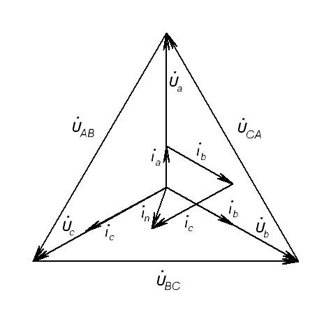
The vector diagram for the case when there is an active load in phase ab, an active-inductive load in phase bc, and an active-capacitive load in phase ca is shown in fig. 3.16, topographic diagram - in fig. 3.17.
Linear current vectors are constructed in accordance with the expressions
İ A = İ ab - İ ca; İ B = İ bc - İ ab; İ C = İ ca - İ bc .
Thus, with an unbalanced load, the symmetry of the phase currents İ ab, İ bc, İ ca is violated, therefore, linear currents İ A, İ B, İ C can only be determined by calculation according to the above equations (3.20) or found graphically from vector diagrams (Fig. 3.16, 3.17).
An important feature connecting the phases of the receiver with a triangle is that when the resistance of one of the phases changes, the mode of operation of the other phases remains unchanged, since the linear voltages of the generator are constant. Only the current of this phase and the line currents in the line wires connected to this phase will change. Therefore, the delta connection scheme is widely used to switch unbalanced loads.
When calculating for an unbalanced load, first determine the values of the phase currents İ ab , İ bc , İ ca and the corresponding phase shifts φ ab , φ bc , φ ca . Then the line currents are determined using equations (3.20) in complex form or using vector diagrams
Four-wire circuit
With a symmetrical voltage system and an unbalanced load, when Z a ≠ Z b ≠ Z c and φ a ≠ φ b ≠ φ c, the currents in the phases of the consumer are different and are determined by Ohm's law
İ a = Ú a / Z a; İ b = Ú b / Z b; İ c = Ú c / Z c.
The current in the neutral wire İ N is equal to the geometric sum of the phase currents
İ N = İ a + İ b + İ c .
The voltages will be U a \u003d U A; U b = U B ; U c \u003d U C, U Ф \u003d U L /, due to the neutral wire at Z N \u003d 0.
Therefore, the neutral wire ensures the symmetry of the phase voltages of the receiver with an unbalanced load.
Therefore, a four-wire network includes single-phase unbalanced loads, for example, electric lamps incandescent. The mode of operation of each phase of the load, which is under a constant phase voltage of the generator, will not depend on the mode of operation of other phases
It is called zero because in some cases the current in it is zero, and neutral based on the fact that it equally belongs to any of the phases.
Purpose of the neutral wire in that it is necessary to equalize the phase load voltages when the resistances of these phases are different, as well as to ground electrical equipment in networks with a solidly grounded neutral.
Thanks to purpose of the neutral wire the voltage on each phase of the load will be almost the same with an uneven load of the phases. The lighting load, switched on by a star, always requires the presence of a neutral wire, since a uniform load of the phases is not guaranteed. in e
The cross section of the neutral wire of three-phase lines in which neutral wires are not used for grounding (special or reconstructed lighting networks) is taken close to half the cross section of the phase wires.
If, for example, phase wires have a cross section of 35 mm2, the neutral wire is taken 16 mm2.
Cross section of neutral wire three-phase system with a dead-earthed neutral, in which the neutral wire is used for grounding, there must be at least half the cross section of the phase wires, and in some cases equal to them.
Zero wire overhead lines 320/220 V must have the same brand and section with phase wires:
in sections made with steel wires, as well as bimetallic and steel-aluminum phase wires, with a cross section of 10 mm2;
if it is impossible to provide the necessary selectivity of protection against short circuits to earth by other means (in this case, it is allowed to take the cross section zero wires more than phase wires).
Since in single- and two-phase lines a current of the same magnitude flows through the neutral and phase wires, then for these lines the cross section of the neutral and phase wires is taken the same
51. Causes of transient processes in electrical circuits. Differential Equations electrical state of circuits and methods for their solution.
Transients occur with any mode change. electrical circuit: when connecting and disconnecting the circuit, when the load changes, when emergency conditions occur (short circuit, wire break, etc.). Changes in the electrical circuit can be represented in the form of certain switching, generally called switching. Physically, transient processes are processes of transition from the energy state corresponding to the switching mode to the energy state corresponding to the post-switching mode.
Transient processes are usually fast: their duration is tenths, hundredths, and sometimes billionths of a second. Relatively rarely, the duration of transient processes reaches seconds and tens of seconds. Nevertheless, the study of transients is very important, since it allows one to establish how the signal is deformed in shape and amplitude, to identify voltage excesses in certain sections of the circuit, which can be dangerous for the isolation of the installation, to increase the amplitudes of currents, which can be tens of times higher than the amplitude of the current of a steady periodic process, and also to determine the duration of the transient. On the other hand, the work of many electrical devices, especially devices industrial electronics, is based on transient processes. For example, in electric heating furnaces, the quality of the produced material depends on the nature of the transition process. Too fast heating can cause rejects, and too slow heating negatively affects the quality of the material and leads to a decrease in productivity.
In the general case, transient processes can occur in an electrical circuit if there are inductive and capacitive elements in the circuit that have the ability to accumulate or give off magnetic or magnetic energy. electric field. At the moment of switching, when the transient process begins, the energy is redistributed between the inductive, capacitive elements of the circuit and external energy sources connected to the circuit. In this case, part of the energy is irrevocably converted into other types of energy (for example, into thermal energy on active resistance).
After the end of the transient process, a new steady state is established, which is determined only by external energy sources. When external energy sources are turned off, the transient process can occur due to the energy of electric magnetic field accumulated before the start of the transient mode in the inductive and capacitive elements of the circuit.
52. The laws of commutation and their use in determining the initial conditions.
The first switching law is that the current in the branch with the inductive element at the initial moment of time after switching has the same value as it had immediately before switching, and then from this value it begins to change smoothly. What has been said is usually written as i L (0 -) = i L (0 +), assuming that switching occurs instantly at the moment t = 0.
The second switching law is that the voltage across capacitive element at the initial moment after switching, it has the same value as it had immediately before switching, and then from this value it begins to change smoothly: U C (0 -) = U C (0 +).
Therefore, the presence of a branch containing inductance in a circuit switched on under voltage is equivalent to breaking the circuit in this place at the moment of switching, since i L (0 -) = i L (0 +). The presence in the energized circuit of a branch containing a discharged capacitor is tantamount to a short circuit in this place at the moment of switching, since U C (0 -) = U C (0 +).
However, in an electrical circuit, voltage surges on inductances and currents on capacitances are possible.
In electrical circuits with resistive elements, the energy of the electromagnetic field is not stored, as a result of which transient processes do not occur in them, i.e. in such circuits, stationary modes are established instantly, abruptly.
In reality, any circuit element has some kind of resistance r, inductance L and capacitance C, i.e. in real electrical devices there are heat loss, due to the passage of current and the presence of resistance r, as well as magnetic and electric fields.
Transient processes in real electrical devices can be accelerated or slowed down by selecting the appropriate parameters of circuit elements, as well as through the use of special devices.
53. Description of the process of charging and discharging a capacitor connected in series with a resistor. The simplest sawtooth voltage generator.
Question 6. What is the neutral wire used for?
Answer6
. The neutral wire is used to equalize the phase voltages at the load terminals. A=  A;
A;  B = b; C= c. In this case, the voltage drops across the load remain equal to the phase voltages of the generator. If the internal resistance of the generator is negligible (equal to zero), then the voltages on the load remain equal to the phase voltages of the generator, constant and do not depend on the load. ( The current will change, but the voltage across the load will not change.).
Question 7. What equations describe the electrical state of the circuit under an asymmetric load?
Answer7
. With an asymmetric load of the phases and the absence of a neutral wire, the phase complexes of the voltage on the load ![]() ,
, ,
, are related to the corresponding complex source voltages Ů A , Ů V, Ů C by the Kirchhoff equations:
 ;
;
 ;
; ;
;
Where  - complex voltage between neutral points of load and source ( networks).
is called neutral bias voltage.
The neutral bias voltage is calculated using the 2-node method:
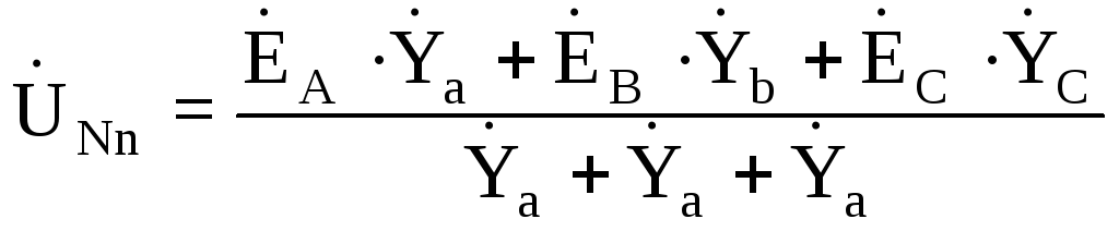
where: Ė - complex EMF,  are the conduction complexes of the load phases.
The load phase currents are found according to Ohm's law:
İ a = a / Z a = ( A- )/Z a;
İ b = b/ Z b = ( B- )/Z b;
İ a = c/ Z c = ( C- )/Z c.
Question 8. How to build combined vector diagrams of voltages and currents for the investigated modes of a three-phase circuit?
Answer8 .
We begin the construction of vector diagrams with linear voltage vectors specified by the network and independent of the conditions of the experiment. This is an equilateral triangle formed by line voltage vectors. The length of the vector corresponds to the line voltage, and the angles between the vectors correspond to the phase shift between the voltage vectors.

Construction of a vector diagram for the case of a uniform load .(symmetric mode).
1. Choose the complex plane (+1,j). We direct the real axis +1 vertically upwards, the imaginary one - along the -X axis. (rotation +90°).
2. Select the voltage scale, for example 1cm→20V. Vector U a (on a scale) is plotted along the real axis +1. The end of the vector is denoted by a small letter A.
3.Vector U b and U c (to scale) draw at +120° and –120° respectively. The ends of the vectors are denoted by small letters b And c respectively.
4. The point corresponding to the origin of coordinates will be denoted by a small letter n. This is the neutral point of the receiver.
5. We build vectors of linear voltages. To do this, we connect the ends of the phase vectors. Get vectors U a b= U A b, U bc = U BC, U c a = U C A. Note that the line voltages of the receiver are equal to the line voltages of the generator.
Dot N on vector diagram, corresponding to the neutral point of the generator, is located in the center of the triangle of linear voltages. In this case, the generator neutral N coincides with the neutral of the receiver n. In general, a point n, corresponding to the neutral point of the load, is found by the serif method. The current vectors are plotted with respect to the corresponding phase voltage vectors, taking into account the phase shift between them.
Below are vector diagrams for various operating modes.
(Fig. 8).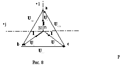
Mode 2 Phase failure A (Fig. 9):
In case of phase A failure and the same load of the other two phases, the neutral point of the receiver n will move to the middle of the line voltage Ů BC . Z b and Z c will be connected in series and connected to line voltage BC. Voltage drop between points A and n will increase, and the phase voltages b and c become equal to half of the linear BC.
![]()
Mode 3 Phase A short circuit (Fig. 9).
When phase A is closed and the other two phases are equally loaded (that is, when the beginning of the load of phase A is connected to the zero point of the load), the point n moves to point A. The phase voltage Ů a becomes zero, the current İ a increases, and the phase voltages b and c become equal to linear.

resistance, Z a ≠ Z b≠ Z c , receiver phase voltages a ≠ b≠ c , a neutral bias voltage appears between the points N and n.
4.1 First, we build a triangle of linear voltages.
4.2. Using the serif method (compass or ruler), from each vertex we set aside the corresponding vectors of the phase voltages of the receiver. The point of intersection of the arcs will give the neutral point of the receiver n. generator neutral point N leave it in its original place.
4.3 Connecting the dot n And N. This is the neutral bias voltage vector U nN (to scale).
4.4 We build the vectors of phase load currents. If the load is light bulbs, which can be represented as active resistances, then there will be no phase shift between the phase voltage and phase current of the load. Therefore, we postpone the current vectors (on a scale) along corresponding phase voltage vectors.
***) In the general case, it is necessary to determine the phase shifts between the current and the corresponding phase voltage according to Ohm's law in complex form and build the current vector using a protractor.

Mode 5. Uneven load with neutral wire (Fig. 11).
In the presence of a neutral wire, the phase voltages of the receiver become equal to the phase voltages of the source A= A; B = b; C= c:
 (1 ratings, on average: 5,00 out of 5)

