The internal resistance of the ammeter. Ammeter - main characteristics, purpose. How to connect an ammeter to an electrical circuit
D.C does not change direction in time. An example would be a battery in a flashlight or a radio, a battery in a car. We always know where the positive stigma of the power supply is, and where it is negative.
Alternating current is a current that changes direction at regular intervals. This current flows in our outlet when we connect a load to it. There is no positive and negative pole, but only phase and zero. The voltage at zero is close in potential to the ground potential. The potential at the phase output changes from positive to negative with a frequency of 50 Hz, that is, the current under load will change its direction 50 times per second.
Ohmmeter: measures electrical resistance, its unit is ohm. It has a small battery that sends current to a resistor for measurement. An ammeter measures the intensity of the electric current that flows through a circuit and must be inserted into it so that all the current passes through it, whereas a voltmeter measures the potential difference between two points in a circuit and must be placed in parallel with the circuit.
Why is it important to calculate the scales of measuring instruments? Score is the smallest measure that is felt in the tool and is error prone, but there is a formula to calculate it and minimize errors. Explain what an oscilloscope is. It is a high-precision electronic measuring instrument that allows you to visualize electrical signals that may change over time.
During one period of oscillation, the current rises from zero to a maximum, then decreases and passes through zero, and then the reverse process occurs, but with a different sign.
Receiving and transmitting alternating current much easier than DC: less energy loss. With the help of transformers, we can easily change the AC voltage.
AC current measurement
Currently, digital oscilloscopes are used. One of its functions is to diagnose faults in electronic circuits TVs, computers, etc. Excess current, or rather, when the current has a higher current, and this can cause heating of the conductive cables.
Do you know what an ammeter is? Have you heard this expression before? If the answer is no, then you are right place! In this post, we will take a detailed look at everything you need to know about this electrical measuring device, which is widely used in the industrial sector, as well as in several technical courses electronics.
High voltage transmission requires less current for the same power. This allows for more subtle arguments. IN welding transformers the reverse process is used - lower the voltage to increase the welding current.
In order for an electrical circuit, it is necessary to turn on an ammeter or milliammeter in series with the power receiver. At the same time, in order to exclude the influence of the measuring device on the operation of the consumer, it must have a very low internal resistance, so that in practice it could be taken equal to zero, so that the voltage drop across the device could simply be neglected.
What is an ammeter and what is it used for?
An ammeter is nothing more than an instrument that serves to measure amplifiers, i.e. electric current intensity. In addition, this block is also used to indicate the direction of the current, where if the indication is positive, it means that electricity circulates clockwise.
Now, if the indication is negative, the direction of the current is counter-clockwise. The ammeter must be connected in series with the system and its internal resistance must be as low as possible. This is because the lower its resistance, the better its performance, given that under these conditions, this device tends to create an inappropriate voltage drop compared to the resistance of resistors.
The inclusion of an ammeter in the circuit is always in series with the load. If you connect an ammeter in parallel with the load, in parallel with the power source, then the ammeter will simply burn out or the source will burn out, since all the current will flow through the meager resistance of the measuring device.

If you are using an AC ammeter, you don't need to worry about its polarity. Now, if the current is continuous, it is important to pay attention to the direction of the current, i.e. current must enter the ammeter at the positive pole and exit at the negative pole.
Another detail you need to consider when using an ammeter is how you measure the current, which should be done in series, not in parallel as is often the case. If you measure in parallel, a short circuit will occur and you will probably have to replace your equipment as the fuses have been damaged.
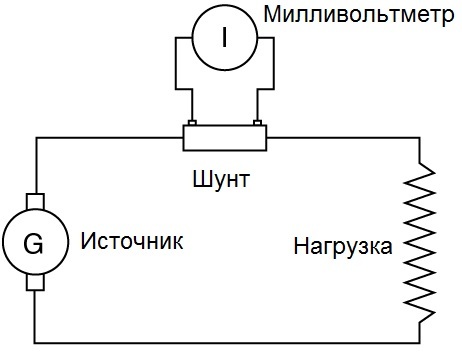
Measurement limits of ammeters intended for measurements in circuits direct current, expandable, by connecting the ammeter not directly with the measuring coil in series with the load, but by connecting the measuring coil of the ammeter in parallel with the shunt.
So, only a small part of the measured current will always pass through the coil of the device, the main part of which will flow through the shunt connected in series to the circuit. That is, the instrument will actually measure the voltage drop across a shunt of known resistance, and the current will be directly proportional to that voltage.
And depending on the ratio short circuit you may also damage the circuit you are measuring. Now you might be wondering: but there are situations where it is not possible to perform this measurement consistently. And in such cases, how to make a measurement?
Well, when serial measurement is not possible, the tip should use an ammeter clip. Now that you know what an ammeter is and what it's for, follow the guidelines given in this post to make sure that the use of this instrument is done correctly and that you have no problem measuring electric current.
In practice, the ammeter will work as a millivoltmeter. However, since the scale of the device is graduated in amperes, the user will receive information about the magnitude of the measured current. The shunt coefficient is usually chosen as a multiple of 10.
Shunts designed for currents up to 50 amperes are mounted directly into the instrument cases, and shunts for measuring high currents are made remote, and then the device is connected to the shunt with probes. For devices intended for permanent operation with a shunt, the scales are immediately graduated in specific values current, taking into account the shunt coefficient, and the user no longer needs to calculate anything.
Then leave your comment and share your questions about it with us! The ammeter connected in series with the resistor and the upstream or downstream voltmeter are then correctly inserted into the circuit. In the exercise, we connected a voltmeter upstream.
Here is a circuit diagram with the upstream voltmeter used in the exercise. For safety reasons, we have added a rheostat in series with the measured resistor to avoid high voltage surges. This is a useful link to avoid damaging the tools. Below is the bottom line of the resulting electrical diagram.
If the shunt is external, then in the case of a calibrated shunt, it indicates rated current and nominal voltage: 45 mV, 75 mV, 100 mV, 150 mV. For current measurements, such a shunt is chosen so that the arrow would deviate to the maximum - to the full scale, that is rated voltages shunt and meter must be the same.
If we are talking about an individual shunt for a specific device, then everything is, of course, simpler. By accuracy classes, shunts are divided into: 0.02, 0.05, 0.1, 0.2 and 0.5 - this is the permissible error in fractions of a percent.
Voltammetric measure of resistance
Electronics and computer engineering - Electrotechnical expertise. Exercise on measuring resistance using the voltammetric method for the course electrical machines Polytechnic University of Turin.
Measuring an Unknown Resistance Using the Short Time Voltammetric Method
Electronics and Computer Engineering is precisely a laboratory report that includes circuits.Electronics and Computer Engineering - report on the use of the voltammetric method. The purpose of the study is to measure the resistance value. Main character of this today is an amperometric caliper. Do you know what it is or what it is for?
Shunts are made of metals with a low temperature coefficient of resistance, and have a significant resistivity: constantan, nickelin, manganin, - so that when the current flowing through the shunt heats it up, this would not be reflected in the readings of the device. To reduce the temperature factor during measurements, an additional resistor made of the same kind of material is connected in series with the ammeter coil.
Whether you're in the industry or you're currently studying, knowing the toolkit is a great starting point. That's why we decided to open a catalog useful tips for shopping. Some of you probably remember that we often dealt with oscilloscopes and spreadsheet multimeters and so much. The main character today is an amperometric caliper.
Ammeter. Current measurement
The name actually says everything that needs to be known about the product in question: explain how it's done, at least externally, and suggest the idea that it's being used to make current measurements. But let's go: does everyone know what cos is?
So that between two points of the circuit, in parallel with the circuit, between these two points, connect a voltmeter. The voltmeter is always connected in parallel with the receiver or source. And so that the connected voltmeter does not affect the operation of the circuit, does not cause a decrease in voltage, does not cause losses, it must have a sufficiently high internal resistance so that the current through the voltmeter can be neglected.
For those who have never seen an instrument like this, know that taking current measurements is not always easy or fast. There are times when the circuit to be checked and discovered cannot be interrupted or the operation cannot be suspended. In these situations, an amperometric caliper is used.
In fact, the classical ammeter should be inserted in series with the circuit and then turned off, cut out, the ammeter inserted and then reconnected. Only then can the value be read. The amperometric caliper runs in parallel and then "hooks", just to the conductor to be tested.
And in order to expand the measurement limits of the voltmeter, an additional resistor is connected in series with its working winding, so that only part of the measured voltage would fall directly on the measuring winding of the device, in proportion to its resistance. And when known value resistance of the additional resistor, the total measured voltage acting in this circuit is easily determined by the voltage fixed on it. This is how all classic voltmeters work.
The working mechanism is really very simple, because the clamp detects the intensity of the electromagnetic field around the cable, so it is based on an induction mechanism. The Hall effect is used to measure continuous currents and is therefore easy to evaluate.
However, there are different types different sizes, which can also be very compact. The clamp can be used to identify and test cables, measure and test diodes, frequency, continuity, electrical resistance, as well as monitoring transition chains, temperature estimates, etc.
The coefficient that appears as a result of adding an additional resistor will show how many times the measured voltage is greater than the voltage falling on the measuring coil of the device. That is, the measurement limits of the device depend on the value of the additional resistor.
An additional resistor is built into the device. To reduce the effect of temperature environment for measurements, the additional resistor is made of a material with a low temperature coefficient of resistance. Since the resistance of the additional resistor is many times greater than the resistance of the device, the resistance of the measuring mechanism of the device as a result does not depend on temperature. The accuracy classes of additional resistors are expressed similarly to the accuracy classes of shunts - in fractions of a percent they indicate the magnitude of the error.
Main features. The test contains a total of 20 questions - 3 extra-answer questions and 17 free answers. You will find the answers at the end of the test. Each question has only one true answer. electric lamps are not necessarily identical. Enter one word or term for each of the following descriptions.
Study the action of a charged body on an electrically neutral object. You have the following items: a plexiglass stick, a silk cloth, and two Styrofoam balls wrapped in metal foil and hanging together on a wooden stick. After wiping with a silk cloth, the plexiglass rod is loaded with a negative charge. Place the stick next to two beads. We observe that both beads are attracted to the stick.
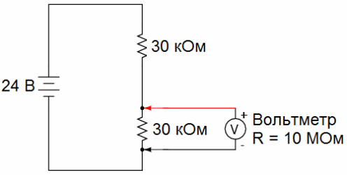
To further expand the measurement limits of voltmeters, voltage dividers are used. This is done so that when measuring, the device has a voltage corresponding to the nominal value of the device, that is, it would not exceed the limit on its scale. The division factor of a voltage divider is the ratio of the input voltage of the divider to the output, measured voltage. The division factor is taken equal to 10, 100, 500 or more, depending on the capabilities of the voltmeter used. The divider does not introduce a large error if the resistance of the voltmeter is also high, and the internal resistance of the source is small.
Explain what happened when the balls touch the stick and why do they bounce? Look at the diagram of an electrical circuit containing a battery connected in series, two lamps and a key that is closed. Explain why this is happening? Look at the diagram in which the lamps are the same. The resistance of the battery, ammeter and connecting wires can be neglected.
Determine the current flowing in the circuit. The negative charge on the stick repels the negative charges in the foil towards the far end of the balls. The sides of the balls near the stick are loaded with a positive charge. Therefore, the balls are electrostatically attracted to the negatively charged rod.
AC current measurement
In order to accurately measure the parameters of alternating current, an instrument transformer is required. The measuring transformer used for measuring purposes also provides personnel with safety, since the transformer achieves galvanic isolation from the high voltage circuit. In general, safety precautions prohibit connecting electrical measuring instruments without such transformers.
High humidity. Touching some of the stick's electrons goes into the foil and charges it with a negative charge. For this reason, the spheres repel each other. The voltages differ in that the difference in lamp resistance is not the same. Lamp 2 will glow less because it draws less voltage.
The other two lamps will not change their light. The main instruments for measuring electrical quantities are an ammeter for measuring current and a voltmeter for measuring voltage. The measured values indicate the scale. In order to read the measured value, it was not loaded with an error when reading on the scale, we must look from above, perpendicular measuring instrument. On the scale scale, in addition to the scale, there are also manufacturer's marks and signs of the measured device, marks containing information about the measuring system, the position of the device in the measurement, the use of the device, accuracy class, test voltage.
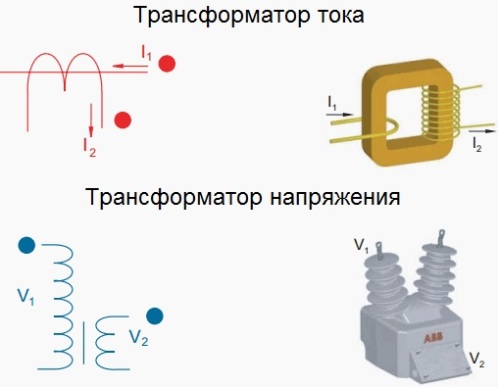
The use of instrument transformers makes it possible to expand the measurement limits of devices, that is, it becomes possible to measure high voltages and currents using low-voltage and low-current devices. So, instrument transformers are of two types: voltage transformers and current transformers.
Rotary coil with rectifier. The horizontal position of the measurement scale. Accuracy class 1. 5; AC and DC voltage can be measured. Electric current is measured with an ammeter by serial connection with the part of the circuit in which we want to measure the electric current. Since the internal resistance of the ammeter is very small, we should never connect directly to it without connecting the instrument to a power source. When measuring direct current, we must ensure that the correct polarity of the device is observed with respect to the voltage source.
Measuring voltage transformer
To measure AC voltage use a voltage transformer. This is a step-down transformer with two windings, the primary winding of which is connected to two points in the circuit between which the voltage must be measured, and the secondary winding is connected directly to the voltmeter. Measuring transformers in the diagrams are depicted as ordinary transformers.
Errors in measuring voltage and current
The range of the ammeter can be increased by using a set of parallel shunts directly in the device. Inserting an ammeter into the circuit causes a decrease in the current we want to measure. When this error is negligible, the resistance of the ammeter should be much less than the sum of the resistances of the outside of the circuit and the internal resistance of the source.
The script presented was created as a proposal for the Life Sciences on Stage review. While working on the production, the text was subsequently modified and modified several times. For readers, we present original form for self-improvement.
A transformer without a loaded secondary winding operates in idle mode, and with a voltmeter connected, the resistance of which is high, the transformer remains practically in this mode, and therefore the measured voltage can be considered proportional to the voltage applied to the primary winding, taking into account the transformation ratio equal to the ratio of the number of turns in the secondary and primary windings.
In this way, high voltage can be measured, while a small safe voltage will be applied to the device. It remains to multiply the measured voltage by the transformation ratio of the measuring voltage transformer.
Those voltmeters that were originally designed to work with voltage transformers have a scale graduation taking into account the transformation ratio, then the value of the changed voltage is immediately visible on the scale without additional calculations.
In order to increase safety when working with the device, in case of damage to the insulation of the measuring transformer, one of the terminals of the secondary winding of the transformer and its frame are first grounded.
Measuring current transformers
Measuring current transformers are used to connect ammeters to AC circuits. These are two-winding step-up transformers. Primary winding is connected in series to the measured circuit, and the secondary is connected to the ammeter. The resistance in the ammeter circuit is small, and it turns out that the current transformer operates almost in short circuit mode, while we can assume that the currents in the primary and secondary windings are related to each other as the number of turns in the secondary and primary windings.

By choosing a suitable ratio of turns, it is possible to measure significant currents, while sufficiently small currents will always flow through the device. It remains to multiply the current measured in the secondary winding by the transformation ratio. Those ammeters that are designed for continuous operation in conjunction with current transformers have scale graduations taking into account the transformation ratio, and the value of the measured current can be easily read on the scale of the device without calculations. In order to increase the safety of personnel, one of the terminals of the secondary winding of the measuring current transformer and its frame are first grounded.
In many applications, feed-through measuring current transformers are convenient, in which the magnetic circuit and the secondary winding are insulated and located inside the feed-through case, through the window of which a copper bus with the measured current passes.
The secondary winding of such a transformer is never left open, because a strong increase in the magnetic flux in the magnetic circuit can not only lead to its destruction, but also induce an EMF dangerous for personnel on the secondary winding. To conduct a safe measurement, the secondary winding is shunted with a resistor of known value, the voltage across which will be proportional to the measured current.
Measuring transformers are characterized by errors of two types: angular and transformation ratio. The first is related to the deviation of the phase shift angle of the primary and secondary windings from 180°, which leads to inaccurate wattmeter readings. As for the error associated with the transformation ratio, this deviation shows the accuracy class: 0.2, 0.5, 1, etc. - as a percentage of the nominal value.
Ammeter- this is an electrical measuring device designed to record the strength of direct or alternating current flowing in a circuit - that is current measuring device . The ammeter is connected in series with the section of the electrical circuit where the current is supposed to be measured. Since the current that it measures depends on the resistance of the circuit elements, the resistance of the ammeter should be as low as possible (very small). This makes it possible to reduce the influence of the current measuring device on the measured circuit and improve their accuracy.
The scale of the instrument is graduated in μA, mA, A and kA, and depending on the required accuracy and measurement limits, a suitable instrument is selected. An increase in the measured current strength is achieved by including shunts, current transformers, magnetic amplifiers in the circuit. This allows you to increase the limit of the measured current value.
Ammeter connection diagrams
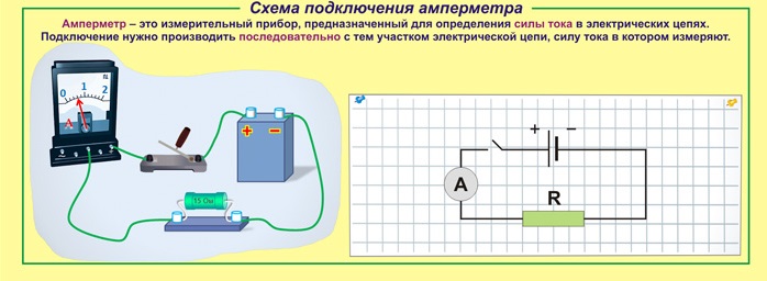
Figure - Scheme of direct connection of the ammeter
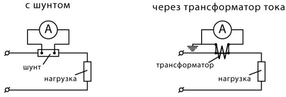
Figure - Scheme of indirect connection of the ammeter through a shunt and a current transformer
Scope of ammeters
Instruments for measuring current have found application in various fields. They are actively used at large enterprises related to the generation and distribution of electrical and thermal energy. They are also used in:
Electrolaboratories;
Automotive;
exact sciences;
Construction.
But not only medium and large enterprises use this device: they are also in demand among ordinary people. Almost any experienced auto electrician has in his arsenal a similar device that allows you to measure the power consumption of appliances, vehicle components, etc.
Types of ammeters
Based on the type of reading device, ammeters are divided into devices with:
With arrow pointer;
With light pointer;
With a writing device;
Electronic devices.
According to the principle of action ammeters are divided into:
1. electromagnetic- are intended for use in circuits of direct, alternating current. Typically used in conventional electrical installations with alternating current with a frequency of 50 Hz.
2. Magnetoelectric- designed to fix the current strength of small values of direct current. They have magnetoelectric measuring device and a scale with graduated divisions.
3. Thermoelectric devices are designed to measure the current strength in high-frequency circuits. The composition of such devices includes a magnetoelectric mechanism, made in the form of a conductor, to which a thermocouple is welded. The current flowing through the wiring causes it to heat up, which is detected by a thermocouple. The resulting radiation, by its influence, causes the frame to deviate by an angle that is proportional to the current strength.
4. Ferrodynamic devices - consist of a closed magnetic circuit made of a ferromagnetic material, a core and a fixed coil. They are characterized by high measurement accuracy, reliable design and low sensitivity to electromagnetic fields.
5. Electrodynamic devices are designed to measure the magnitude of the current in high-frequency DC / AC circuits (up to 200 Hz). They are sensitive to overloads and external electromagnetic fields. But due to the high measurement accuracy, they are used as control devices for verification of current ammeters.
6. Digital ammeters - modern model devices, combining the advantages of analog devices. Today, such devices have won a leading position. This is due to ease of use, ease of use, small size and high accuracy of the obtained measurement results. In addition, digital devices can be used in a variety of conditions: it is not afraid of shaking, vibration, and other influences.
Consider a few ammeters different manufacturers and different types:
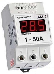 1. Ammeters Am-2 DigiTOP
Specifications:
Number of inputs 1
Measured alternating current 1 ... 50 A
Measurement error 1%
Display resolution 0.1 A
- supply voltage -100...-400 V, 50 (+1) Hz dimensions 90x51x64mm
The performance and durability of household electrical appliances depend on the quality of the electricity received. Usually to failure electronic engineering whether it be refrigerators, televisions or washing machines, leads to an increase in voltage above the permissible limits. The most dangerous is a prolonged increase in voltage above the permissible mark. At the same time, the power supplies of electronic equipment fail, the windings of electric motors overheat, and fire often occurs.
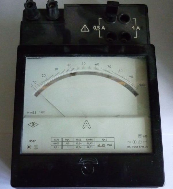 2. laboratory ammeter E537
This device (ammeter E537) is intended for accurate measurement current strength in AC and DC circuits.
Accuracy class 0.5.
Measuring ranges 0.5 / 1 A;
Weight 1.2 kg.
Technical characteristics of the ammeter E537:
Measuring range end value 0.5 A/1 A
Accuracy class 0.5
Normal frequency range (Hz) 45 - 100 Hz
Operating frequency range (Hz) 100 - 1500 Hz
Dimensions 140 x 195 x 105 mm
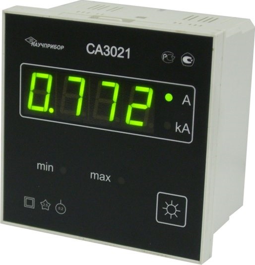
The base model ammeter digital device is available in several standard modifications depending on the base value of the measured current parameters. When ordering this digital ammeter model, please state with what base parameter current you have to work: 1 A, 2 A or 5 A.
Basic parameters of the measured current, In-1 Ampere (CA3020-1), 2 Ampere (CA3020-2) or 5 Ampere (CA3020-5);
Limits of measured currents from 0.01 In to 1.5 In;
Frequency range for measured currents from 45 to 850 Hertz;
The limits of the basic permissible existing error ± 0.2% to optimal value parameters of the measured current strength;
supply voltage - AC voltage (85-260) Volts and frequency (47-65) Hertz or direct voltage (120 - 300) Volts;
The power consumed by the device is not more than 4 VA;
Dimensional dimensions 144x72x190 mm;
Weight not more than 0.55 kg;
The power consumed by the measuring circuit of the 3020 series ammeters does not exceed: for СА3020-1 - 0.12 VA; for SA3020-2 - 0.25 VA; for SA3020-5 - 0.6 VA.
 (1 ratings, on average: 5,00 out of 5)

