Calculation of single-phase short circuit current. Calculation of two-phase short circuit
Three-phase short circuit current from the supply network is determined in kiloamperes according to the formula:
where U N NN is the average rated phase-to-phase voltage, taken as the base voltage; for 0.4 kV networks, the base voltage is taken to be 400 V;
The total total resistance of the circuit up to the point of a three-phase short circuit, which is the positive sequence resistance and is determined by the formula in millioms:
where R 1∑ is the total active resistance of the circuit up to the short-circuit point, mOhm;
X 1∑ - total inductive reactance up to the short-circuit point, mOhm.
The total active resistance includes the resistance of the following elements:
The total inductive reactance contains the resistances of the following elements:
Two-phase current K3 is determined in kilometers using the following formula:
![]() ,
,
where is the average rated phase-to-phase voltage, taken as the base voltage, V;
and are the total total resistances of the direct and negative sequences, and and is equal to mOhm.
Expression (19) can be written as follows
![]() =,
=,
where is the total resistance of the circuit to point K3 with a two-phase short circuit, mOhm.
![]() ,
,
Single-phase current short circuit determined by the formula:
Total active and inductive zero-sequence resistance to location K3, respectively, mOhm.
36. Thermal resistance of devices.
Thermal resistance electrical apparatus is called the ability to withstand them without damage preventing further work, the thermal effect of currents flowing through live parts of a given duration. A quantitative characteristic of thermal resistance is the thermal resistance current flowing over a certain period of time. The most intense is the short circuit mode, during which currents can increase tens of times compared to the rated ones, and the power of heat sources can increase hundreds of times.
37.Dynamic resistance of devices
Electrodynamic resistance device is called its ability to withstand electrodynamic forces(EDF), which arose during the passage of short-circuit currents. This value can be expressed either directly by the amplitude value of the current i ding, in which the mechanical stresses in the parts of the device do not exceed the permissible values, or the multiple of this current relative to the amplitude rated current. Sometimes the electrodynamic resistance is assessed effective values current for one period (T = 0.02 s, f = 50 Hz) after the onset of the short circuit.
38. Procedure for calculating short circuit currents.
A short circuit (SC) is the connection of live parts different phases or potentials between each other or with the housing of equipment connected to the ground, in power supply networks or in power receivers. A short circuit can occur for various reasons, for example, deterioration of insulation resistance: in a humid or chemically active environment; in case of unacceptable heating or cooling of the insulation; mechanical failure of insulation. A short circuit can also occur as a result of erroneous actions by personnel during operation, maintenance or repair, etc.
During a short circuit, the current path is “shortened” as it travels through the circuit bypassing the load resistance. Therefore, the current increases to unacceptable levels unless the power to the circuit is turned off by the protection device. The voltage may not turn off even with a protection device if the short circuit occurs at a remote point and therefore the resistance electrical circuit will be too high, and the current value for this reason will be insufficient to trigger the protection device. But a current of this magnitude may be sufficient to cause a dangerous situation, such as a wire fire. Short circuit current also produces an electrodynamic effect on electrical devices - conductors and their parts can be deformed under the influence mechanical forces, arising at high currents.
Based on the above, protection devices should be selected according to the conditions of the short-circuit current value (electrodynamic strength, indicated in kA) at the location of their installation. In this regard, when selecting a protection device, it becomes necessary to calculate the short circuit current (SCC) of the electrical circuit. The short circuit current for a single-phase circuit can be calculated using the formula:
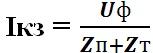
where Is is the short-circuit current, Uph is the phase voltage of the network, Zp is the resistance of the circuit (loop) phase-zero, Zt is the total resistance of the phase winding of the transformer on the low-voltage side.
where Rп is the active resistance of one wire of the short circuit circuit.
where ro - resistivity conductor, L is the length of the conductor, S is the cross-sectional area of the conductor.
Xn is the inductive reactance of one wire of a short circuit circuit (usually taken at the rate of 0.6 Ohm/km).
Transformer short circuit voltage (% of Un):
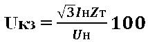
Hence the total resistance of the phase winding of the transformer (Ohm):
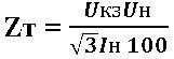
where Us - short-circuit voltage of the transformer (in % of Un) is given in reference books; Un - Rated voltage transformer, In - rated current of the transformer - are also taken from reference books.
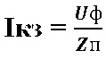
The above calculations are performed at the design stage. In practice, it is difficult to do this at existing facilities due to the lack of initial data. Therefore, when calculating the short-circuit current, in most cases it is possible to take the resistance of the phase winding of the transformer Zt equal to 0 (real value ≈ 1∙10-2 Ohm), then:
The given formulas are suitable for ideal conditions. Unfortunately, they do not take into account such factors as twists, etc., which increase the active component of the Rп chain. Therefore, an accurate picture can only be given by direct measurement of the resistance of the phase-zero loop.
39.Release current, current setting, cut-off current circuit breaker .
Release
The current flowing through the electromagnetic release of the circuit breaker causes the circuit breaker to turn off when it quickly and significantly exceeds the rated current of the circuit breaker, which usually occurs when there is a short circuit in the protected wiring. A short circuit corresponds to a very quickly increasing high current, which the device takes into account electromagnetic release, which allows you to almost instantly influence the tripping mechanism of the circuit breaker with a rapid increase in the current flowing through the release solenoid coil. The response speed of the electromagnetic release is less than 0.05 seconds.
Setpoint current on the scale is marked by the factory; in the table everywhere, except where otherwise specified, it is indicated as a percentage of the rated current of the release. Between the lower and upper limits indicated on the scale, the settings are adjusted smoothly.
Cut-off e that is the minimum current value that causes instantaneous operation of the machine).
CALCULATION WORK
Subject:“CALCULATION OF TWO-PHASE SHORT CIRCUIT”
Goal of the work: Development of skills in calculating short circuits in electrical circuits.
Option number 2.
Task No. 1. Figure 1 shows a two-phase short circuit diagram. Define:
1. Impedance of direct sequence of two phases (2Zph);
2. Short circuit current (Ik);
3. Phase EMF (EA).
Since the voltage during a two-phase short circuit does not contain zero-sequence components at any point in the network, the following condition must be satisfied:
3Uo = UAK + UBK + UCK = 0, with UA = EA
Rice. 1. Diagram of a two-phase short circuit
Initial data: ZB = 25 Ohm; ZС = 15 Ohm; EBC = 90 V; UВК = 100 V.
Solution progress:
Figure 1 shows a metal short circuit between phases IN And WITH Power lines. Under the influence of phase-to-phase EMF EMU(Fig. 1) short-circuit currents arise IVCAndISk.
Their values are determined by the formula:
ITO(2) =EVS /2 ZF, (1)
Where 2 ZF– impedance of direct sequence of two phases.
Positive sequence impedance 2 ZF determined by the formula:
2 ZF= ZIN+ ZWITH, (2)
Where ZIN, ZWITH– impedance of phases B and C, respectively.
1. Using formula (2), we determine the total resistance of a direct sequence of two phases (2Zph):
2 ZF= 25 Ohm + 15 Ohm = 40 Ohm.
2. Using formula (1), we determine the two-phase short circuit current:
ITO(2) =90 V/40 Ohm =2.25 A.
The currents in the damaged phases are equal in value, but opposite in phase, and the current in the undamaged phase is zero (if the load is not taken into account): IVC= ISk, I.A. = 0.
There is no zero sequence current (ZC) during a two-phase short circuit, since the sum of the currents of the three phases I A+ I B+ I C= 0 .
Undamaged phase voltage A the same at any point in the network and equal to the phase EMF: U A= E A. Since the phase-to-phase voltage during a metallic fault at the fault point U B.C.To= U BTo – U CTo= 0, then U BTo = U CTo,
i.e., the phase voltages of the damaged phases at the location of the short circuit are equal in magnitude and coincident in phase.
Since phase voltages during a two-phase short circuit do not contain NP components, the following condition must be satisfied at any point in the network:
Considering that in the place of short circuit U B.K.= U CK And U A.K.= E A, we find
![]() (3)
(3)
Consequently, at the location of the short circuit, the voltage of each damaged phase is equal to half the voltage of the undamaged phase and is opposite in sign.
3. From formula (3) we determine the phase EMF of the undamaged phase (EA):
EA =–UBK /2.
EA =– 100 V /2 = – 50 V.
Two-phase short circuits are characterized by two features:
1) the current and voltage vectors form an asymmetrical but balanced system, which indicates the absence of NP components. The presence of asymmetry indicates that currents and voltages have negative sequence (NP) components along with direct sequence;
2) phase voltages, even at the short-circuit location, are significantly greater than zero, only one phase-to-phase voltage drops to zero, and the value of the other two is 1.5 UF. Therefore, a two-phase short circuit is less dangerous for the stability of the EPS and electricity consumers than a three-phase short circuit.
Task No. 2.
Draw a diagram for connecting a voltage transformer to a star. Explain the operation of this circuit. |
|
According to GOST 11677-75, the beginnings and ends of the primary and secondary windings of transformers are designated in a certain order. The beginnings of the windings of single-phase transformers are designated by the letters A, a, and the ends by X, x. Capital letters belong to the higher voltage windings, and small ones - to the lower voltage windings. If in a transformer, in addition to the primary and secondary, there is also a third winding with an intermediate voltage, then its beginning is designated Am, and its end Xm.
In three-phase transformers, the beginnings and ends of the windings are designated: A, B, C; X, Y, Z - highest voltage; Am, Bm, Cm; Xm, Ym, Zm - average voltage; a, b, c; x, y, z - lowest voltage. In three-phase transformers with star-connected phases, in addition to the beginning of the windings, the neutral is sometimes also brought out, i.e. common point connecting the ends of all windings. It is denoted by O, Om and o. Figure 1, a, b shows the star and delta winding connection diagrams as they are depicted for three-phase transformers.
DIV_ADBLOCK258">

a - emf E1 and E2 are in phase; b - emf E1 and E2 are shifted in phase by 180°; 1 - turn primary winding; 2 - turn secondary winding
Figure 2 - Angular displacement of vectors electromotive forces depending on the designation of the ends of the winding
Let us now assume that we have changed the designations of the beginning and end of the turn in the secondary winding (Figure 2, b). No change in the physical process of emf induction will occur, but in relation to the ends of the turn, the direction of the emf will change to the opposite, i.e., it will not be directed from the beginning to the end, but vice versa - from the end (x) to the beginning (a). Since nothing has changed in turn 1, we must assume that the emfs E1 and E2 are 180° out of phase. Thus, a simple change in the designations of the ends is equivalent to an angular shift of the emf vector in the winding by 180°.
However, the direction of the emf can also change in the case when the beginnings and ends of the primary and secondary windings are located equally. The fact is that the transformer windings can be made right or left. The winding is called right-handed if its turns, when wound, are arranged clockwise, that is, they are laid along the right helical line (Figure 3, top winding). The winding is called left-handed if its turns, when wound, are positioned counterclockwise, i.e., they are laid along the left helical line (Figure 3, bottom winding).
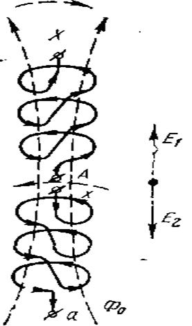
Figure 3 - Angular displacement of EMF vectors depending on the direction of winding of the windings
As can be seen from the figure, both windings have the same end designation. Due to the fact that the windings are penetrated by the same flux, the direction of the emf in each turn will be the same. However, due to different windings, the direction of the total emf of all series-connected turns in each winding is different: in the primary, the emf is directed from the beginning of A to the end of X, and in the secondary, from the end of x to the beginning of a. So, even with the same designation of the ends, the emf of the primary and secondary windings can be shifted by an angle of 180°.
In a single-phase transformer, the emf vectors of the windings can either coincide or be oppositely directed (Figure 4, a, b). If such a transformer operates alone, then it is completely indifferent to consumers how the emf is directed in its windings. But if three single-phase transformers work together on a line three-phase current, then for proper operation it is necessary that in each of them the emf vectors are directed either as shown in Figure 4, a, or as shown in Figure 4, b.
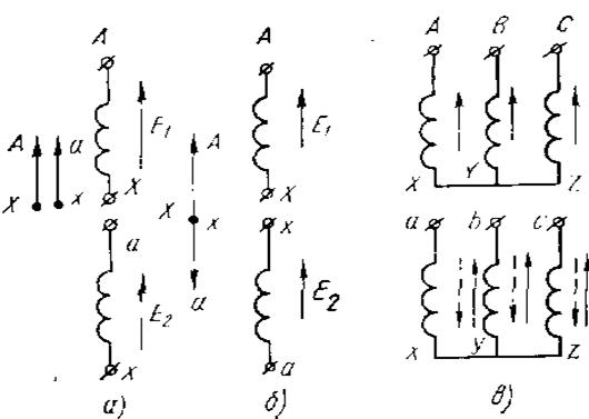
a, b - single-phase; c - three-phase
This applies to the same extent to each three-phase transformer. If in the primary windings the emf in all phases has the same direction, then in the secondary windings the direction of the emf must be the same (Figure 4, c). Obviously, for the secondary windings, the winding direction and the designation of the ends must also be the same.
If the winding is incorrectly installed with a different winding direction or if the ends are connected incorrectly, the voltage received by consumers will sharply decrease, and normal operation will be violated. Particularly unfavorable conditions arise if several transformers operate simultaneously from the same network, in which the phase shifts between the linear emfs are different. To avoid disruptions in the operation of consumers, you should have transformers with certain angular displacements of the winding emf vectors.
The directions of the emf vectors and the angular displacements between them are usually characterized by winding connection groups. In practice, the angular displacement of the emf vectors of the LV and MV windings relative to the emf vectors of the HV winding is denoted by a number, which, when multiplied by 30°, gives the lag angle of the vectors. This number is called the connection group of the transformer windings.
Thus, if the windings’ emf vectors coincide in direction (angular displacement 0°), connection group 0 is obtained (Figure 4, a). Angular displacement of 180° (Figure 4, b) corresponds to group 6 (30 x 6=180°). As we have seen, in the windings of single-phase transformers there can only be such angular displacements, therefore only the 0th and 6th groups of connections are possible for them. For brevity, the winding connections of single-phase transformers are designated I/I - 0 and I/I - 6.
In three-phase transformers, the windings of which can be connected in a star or triangle, the formation of 12 various groups with a phase shift of linear emf vectors from 0 to 360° every 30°. Of the twelve possible groups of connections, two groups have been standardized in Russia: 11th and 0th with a phase shift of 330 and 0°.
Let us consider as an example the connection diagrams Y/Y and Y/Δ (Figure 5, a, b). Let us depict the windings located on one rod one below the other; Let us assume that the winding of all windings (primary and secondary) is the same; the directions of phase emf are shown by arrows.
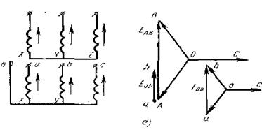
Figure 5 - Obtaining a group of connections in a star-star circuit (a) Let's construct a vector diagram of the emf of the primary winding (Figure 5, a) so that the phase emf vector C is located horizontally. By connecting the ends of vectors A and B, we obtain the vector of linear emf EAB (AB). Let's construct a vector diagram of the emf of the secondary winding. Since the directions of the emf of the primary and secondary windings are the same, the phase emf vectors of the secondary winding are built parallel to the corresponding vectors of the primary winding. By connecting points a and b and attaching the vector Eab (ab) to point A, we make sure that the angular displacement between the linear emf of the primary and secondary windings is equal to 0. So, in the first example, the winding connection group is 0. This is denoted as follows: Y/Yн -0 , which reads “star with neutral removed.”
When considering the second example (Figure 5, b), we see that the vector diagram of the emf of the primary winding is constructed in the same way as in the previous example. When constructing a vector diagram of the emf of the secondary winding, it should be remembered that when connected into a triangle, the phase and linear emfs coincide both in magnitude and direction.
We construct the phase emf vector c, directing it parallel to the vector C of the primary winding. The end of phase c (point z) is connected to the beginning of phase b, therefore, from the end of vector c we draw the emf vector of phase b parallel to vector B. The end of phase b is connected to the beginning of phase a, therefore from the end of vector b (point y) we draw the emf vector of phase a parallel to vector A. In the resulting closed triangle abc, vector ab is the linear emf Eab. By attaching vector Eab to point A, we make sure that it is shifted relative to vector EAB by an angle of 30° in the leading direction. Consequently, the Eab vector lags 330° (30° x 11 = 330°) from the HV winding emf vector. So, in this example, the winding connection group is 11. This is denoted as follows: Y/Δ -11, which reads: “star - delta - eleven”.
In a three-winding transformer, the winding connection group is determined similarly; in this case, the windings are considered in pairs: the primary and one of the other two. If you encounter the designation Yн/Y/Δ - 0 - 11, then it should be read as follows: “star with neutral removed - star - triangle - zero - 11.” This means that for the three-winding transformer under consideration, the HV winding is connected in a star with an output zero point, the MV winding is in a star, the LV winding is in a triangle, the connection group of the HV and MV windings is zero, the HV and LV windings are 11.
We considered only two connection groups - 0 and 11. By changing the designations of the ends (by moving the designations in a circular manner), you can get other groups from 1 to 10. However, these groups are not widespread and are very rare. In Russia, only three groups are standardized: Y/Y - 0, Y/Δ - 11 for three-phase transformers, I/I - 0 - for single-phase transformers.
Bibliography
1. and others. Electrical engineering /,: Textbook. manual for universities. – M.: Energoatomizdat, 2007. – 528 p., ill.
2. , Nemtsov: Proc. manual for universities. – 4th ed., revised. – M.: Energoatomizdat, 2009. – 440 p., ill.
3. Basics industrial electronics: Textbook for non-electrical engineering. specialist. universities /, O M. Knyazkov, A E. Krasnopolsky, ; edited by . – 3rd ed., revised. and additional – M.: Higher. school, 2006. – 336 p., ill.
4. Electrical engineering and electronics in 3 books. Ed. Book 1. Electrical and magnetic circuits. – M.: Higher school. – 2006
5. Electrical engineering and electronics in 3 books. Ed. Book 2. Electromagnetic devices and electric cars. – M.: Higher school. – 2007
Purpose and conditions for constructing vector diagrams. To understand the operating conditions of the relays, it is convenient to use vector diagrams of the voltages and currents supplied to them. The following starting points are taken as the basis for constructing vector diagrams: for simplicity, the initial moment of a short circuit on a power line with one-way power supply in the absence of load is considered (Fig. 1.3, A); to obtain the actual phase angles between currents and voltages, the voltage drop is taken into account not only in the inductive, but also in the active resistance R short circuit circuits; electrical system, feeding the short circuit, is replaced by one equivalent generator with phase EMF E A, E IN, E WITH, representing symmetrical and balanced *1 a system of vectors relative to which vectors of currents and voltages are constructed.
To simplify the construction of diagrams, metal short circuits are usually considered, in which the transition resistance at the fault point RП = 0. The positive direction of currents is taken to be their direction from the power source to the place of damage; accordingly, EMF and voltage drops, the directions of which coincide with the direction of the positive current, are considered positive.
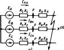
Vector diagram with a three-phase short circuit. In Fig. 1.4, A shows a power line on which a metal short circuit of three phases has occurred at the point TO. Construction of a vector diagram (Fig. 1.4, b) starts with phase EMF E A, E IN, E WITH. Under the influence of phase EMF, a short-circuit current arises in each phase:
Where EF– phase EMF of the system; ZС,RC,XC;ZL.K,RL.K,XL.K– resistance of the system and the damaged section of the power line (Fig. 1.4, A).
Currents IAk=IВк=ISc=Ik have a phase shift relative to the corresponding EMF:
![]()
 |
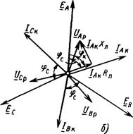 |
Fig.1.4. Three-phase short circuit: A- scheme; b- vector diagram of currents and voltages |
|
Stress at a point TO are equal to zero: UАк=UВк=UСк=0. Phase voltages at the installation site of the relay protection, at the point R(Fig. 1.4, A), U AP=I AkRЛ.К+j I AkXL.K are determined on the diagram (Fig. 1.4, b) as the sum of voltage drops in active resistance I AkRL, in phase with the vector I Ak, and in reactance I AkXL, shifted by 90° relative to I Ak. Vectors are constructed similarly U
B.P. And U
C.P.. Modules (absolute values) U
AP, U
B.P.,U
C.P. have same values, each of these vectors advances the current of the same phase by an angle φк =arctg(XL.K/RL.K). For a 35 kV transmission line, this angle is 45–55°, 110 kV – 60–78°, 220 kV (one wire in phase) – 73–82°, 330 kV (two wires in phase) – 80–85°, 500 kV (three wires in phase) – 84–87°, 750 kV (four wires in phase) – 86–88°. Greater value φк corresponds to a larger cross-section of the wire, since the larger the cross-section, the smaller R.

From the considered diagrams of three-phase short circuits it follows: 1) vector diagrams of currents and voltages are symmetrical and balanced, since they do not contain negative and zero sequence components; 2) three-phase short circuit is accompanied by a sharp decrease in all between phase voltages(both at the short circuit location and close to it). As a result K(3) is the most dangerous damage to the stability of parallel operation of the power system and electricity consumers.
Two-phase short circuit. In Fig. 1.5, A shows a metal short circuit between phases IN And WITH Power lines. Under the influence of phase-to-phase EMF EMU(Fig. 1.5, A) short-circuit currents arise IВк andISc.
Their values are determined by the formula IК(2)=ЭВС/2ZF, Where 2 ZФ– total resistance of direct sequence of two phases ( 2 ZФ=ZB+ZС). The currents in the damaged phases are equal in value, but opposite in phase, and the current in the undamaged phase is zero (if the load is not taken into account):
Zero sequence current (NP) at K(2) is absent, since the sum of the currents of the three phases I A+I B+I C= 0.
TO. In Fig. 1.5, b vectors of phase EMF and EMF between damaged phases are constructed E Sun. Short circuit current vector I kV lags behind the emf creating it ![]()
Undamaged phase voltage A the same at any point in the network and equal to the phase EMF: U A=E A. Since the phase-to-phase voltage during a metallic fault at the fault point U BCk=U Bk – U Cck= 0, then:
Those. the phase voltages of the damaged phases at the short-circuit location are equal in magnitude and coincident in phase.
Since phase voltages during a two-phase short circuit do not contain NP components, the following condition must be satisfied at any point in the network:
Considering that in the place of short circuit U BK=U CK And U AK=E A, we find
![]() (1.3b)
(1.3b)
Consequently, at the location of the short circuit, the voltage of each damaged phase is equal to half the voltage of the undamaged phase and is opposite in sign. On the diagram vector U A.K. coincides with the vector E A, and the vectors U B.K. And U CK – equal to each other and opposite in phase to the vector E A.
Vector diagram at a point P is shown in Fig. 1.5, V. The current vectors remain unchanged. Phase voltages IN And WITH at the point R are equal:
The farther the point R distance from the short circuit location, the greater the voltage: U BSR= U VR– U SR U AP= E A. Current vector I B.P. lags behind phase-to-phase voltage U BCP at an angle φк=arctg(XL/ RL) .
Two-phase short circuits are characterized by two features:
1) the current and voltage vectors form an asymmetrical but balanced system, which indicates the absence of NP components. The presence of asymmetry indicates that currents and voltages have negative sequence (NP) components along with direct sequence;
2) phase voltages, even at the short-circuit location, are significantly greater than zero, only one phase-to-phase voltage drops to zero, and the value of the other two is 1.5 UФ. Therefore, a two-phase short circuit is less dangerous for the stability of the EPS and electricity consumers.
Single phase short circuit (K(1)). A ground fault of one phase causes a short-circuit current to appear only in electrical networks 110 kV and above, working with solidly grounded neutrals of transformers. The nature of currents and voltages that appear during this type of phase damage A, explains Fig. 1.6, A.
Short circuit current Iac arising under the influence of EMF EA, passes through the damaged phase from the power source G and returns back across the earth through grounded neutrals N transformers:
![]() (1.5)
(1.5)
Fig.1.6. Single-phase short circuit:
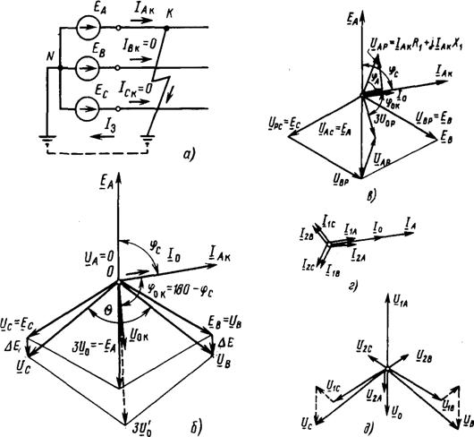
A - scheme; vector diagrams of currents and voltages at the short circuit location ( b) and at the location where the relay is installed R (V), currents ( G) and stresses ( d) symmetrical components at the short circuit location
Inductive and active resistances in this expression correspond to the phase-ground loop and differ from the phase resistance values for phase-to-phase short circuits. Vector I Ak lags behind the EMF vector EA at an angle ![]() There are no currents in undamaged phases.
There are no currents in undamaged phases.
Damaged phase voltage A at the point TO UАК=0 . Voltages of undamaged phases *2 IN And WITH equal to the EMF of these phases:
![]() (1.6)
(1.6)
The vector diagram for the damage location is shown in Fig. 1.6, b. Phase-to-phase voltages U ABK=U B.K.; U BCK=U BK –U CK;U CAK=U CK.
The geometric sums of phase currents and voltages are equal:
From here it is clear that phase currents and voltages contain NP components:
![]()
Vector I 0 K is in phase with I A.K. vector U 0 K opposite in phase E A and is equal to 1/3 of the normal (before short-circuit) voltage value of the damaged phase A:
U 0 K= – 1/3E A= –1/3U AN. Current I 0 K ahead of the voltage U 0 K at 90°.
Vector diagram at a point R at K(1) is shown in Fig. 1.6, V. Phase current A remains unchanged. Damaged phase voltage
Vector U AP ahead I Ak at an angle φк=arctg(Xl(1)/Rл(1)).
Voltages of undamaged phases IN And WITH do not change: U BP=E B; U CP=E C. Phase-to-phase voltages UABPUACP and increase. Vectors NP I 0 P And U 0 P are equal:
As the diagram shows, U oP U oK in absolute value and is shifted in phase due to the presence active resistance RKP(1)(phase-ground). Let us note some features of vector diagrams (Fig. 1.6, b And V):
1) currents and phase voltages form an asymmetrical and unbalanced system of vectors, which indicates the presence of, in addition to the direct components, OP and NP;
2) phase-to-phase voltages at a point TO greater than zero, the area of the triangle formed by these stresses differs from zero. Single-phase short circuit is the least dangerous looking damage from the point of view of the stability of the EPS and the operation of consumers.
Two-phase short circuit to ground(K(1,1)). This type of short circuit can also only occur in a network with solidly grounded neutral(see Fig. 1.2, G). The vector diagram of a short circuit to ground of two phases is shown in Fig. 1.7 for points TO And R.
Under the influence of EMF E IN And E WITH in damaged phases IN And WITH
Currents flow I VC And I Sk ground-connected:
![]() (1.8)
(1.8)
There is no current in the undamaged phase:
The sum of the currents of all three phases, taking into account (1.8) and (1.9), is not equal to zero: I Ak+I VK+I Sk=I K(3)=3I 0 , total currents contain an NP component.
At the location of the short circuit voltage of the damaged phases IN And WITH, closed to ground, are equal to zero: UBK=UCK=0. The voltage between the damaged phases is also zero: UBCK=0. Undamaged phase voltage UAK remains normal (if we neglect induction from currents I VC And I Sk). At the point TO phase-to-phase voltage triangle (Fig. 1.7, V) turns into a line, and the phase-to-phase voltages between damaged and undamaged phases U AB And U C.A. are reduced to phase voltage U A.K.. Diagram of currents and voltages for a point R built in Fig. 1.7, b.
Due to increased stress UBP And UCP The phase-to-phase voltages also increase, the area of the triangle of phase-to-phase voltages increases and the voltage of the voltage decreases:
![]()
Fig.1.7. Two-phase earth fault:
A- scheme; vector diagrams of currents and voltages at the short circuit location and at the relay installation location R (b); zero sequence voltage and phase voltages at the short circuit location ( V) and at the point R (G)
Vector diagrams for two-phase ground faults have the following features:
1) currents and voltages are asymmetrical and unbalanced, which causes the appearance of, in addition to the direct components, NP and OP;
2) due to a sharp decrease in voltage at the short circuit point, this type of damage after K(3) is the most severe for the stability of the power system and electricity consumers.

Double earth fault (K(1)). A similar short circuit occurs in a network with an isolated or grounded neutral through an arc suppression reactor. Under double circuit implies a ground fault of two phases at different points in the network (K1 And K2 in Fig. 1.8). Under the influence EMF difference damaged phases E IN-E WITH in phases IN And WITH K3 currents arise I VC And I Sk, closing through the ground at points K1 And K2. At these points and in damaged phases, the short-circuit currents are equal in value and opposite in phase: I Vk=-
I Sk; undamaged phase A current I AK = 0.
Vector diagram of currents in the area between the power source and the nearest fault point (point K1) will be the same as for a two-phase short circuit without ground (see § 1.3, Fig. 1.5). The sum of the phase currents in this section is zero ( I Ak+I Vk=I Sk=0), therefore, there are no NP components in the phase currents.
On a power line section between ground fault points K1 And K2 in conditions one way supply short-circuit current flows through only one phase (phase IN in Fig. 1.8), i.e. the same as with a single-phase short circuit (see § 1.3). The vector diagram of total currents and voltages in this section is similar to the diagram for single-phase short circuits (see Fig. 1.6, b EMF of mutual induction increases the voltage of undamaged phases and reduces the phase shift angle between them (0 Δ E not taken into account.
 (1 ratings, on average: 5,00 out of 5)

