Connection of conductors. Ohm's law for a complete circuit. Electromotive force
Ohm's law for a section of a circuit: current strengthI Location on electrical circuit directly proportional to voltageU at the ends of the section and is inversely proportional to its resistance R.
Formula of the law:
I
=. From here we write the formulas U
=
IR
And R=
 .
.
 Fig.1. Chain section
 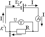 Fig.2. Complete chain
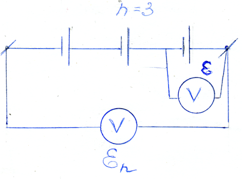
Ohm's law for complete chain: current strengthI
complete electrical circuit equal to the emf (electromotive force) of the current source E divided by the total resistance of the circuit (R+r). The total resistance of the circuit is equal to the sum of the external circuit resistances R and internal r current source. Formula of the law I =
 .
In Fig. 1 and 2 show diagrams of electrical circuits.
.
In Fig. 1 and 2 show diagrams of electrical circuits.
3. Series and parallel connection of conductors
Conductors in electrical circuits can be connected sequentially And parallel. A mixed compound combines both of these compounds.
A resistance, when turned on instead of all other conductors located between two points in the circuit, the current and voltage remain unchanged, is called equivalent resistance these conductors.
Serial connection
A connection is called serial in which Each conductor is connected to only one previous and one subsequent conductor.
As follows from the first Kirchhoff's rules, when conductors are connected in series, the strength of the electric current flowing through all conductors is the same (based on the law of conservation of charge).
1. When serial connection conductors(Fig. 1) The current strength in all conductors is the same:I 1 = I 2 = I 3 = I
 Rice. 1.Serial connection of two conductors.
2. According to Ohm's law, voltage U 1 And U 2 on the conductors are equal U 1 = IR 1 , U 2 = IR 2 , U 3 = IR 3 .
The voltage when connecting conductors in series is equal to the sum of the voltages in individual sections (conductors) of the electrical circuit.
U = u1 + u2 + u3
Ohm's law, voltage U 1, U 2 on the conductors are equal U 1 = IR 1 , U 2 = IR 2 , In accordance with Kirchhoff's second rule, the voltage throughout the entire section is:
U = U 1 + U 2 = IR 1 + IR 2 = I(R 1 + R 2 )= I·R. We get:R = R 1 + R 2
Total voltageU on the conductors is equal to the sum of the voltagesU 1 , U 2 , U 3 equals:U = U 1 + U 2 + U 3 = I · (R 1 + R 2 + R 3 ) = IR
WhereR EKV – equivalent resistance of the entire circuit. From here: R EKV = R 1 + R 2 + R 3
With a series connection, the equivalent resistance of the circuit is equal to the sum of the resistances of the individual sections of the circuit : R EKV = R 1 + R 2 + R 3 +…
This result is true for any number series connected conductors.
From Omas law it follows: if the current strengths are equal in a series connection:
I
=
 ,
I
=
,
I
=
 . From here
=
or
. From here
=
or
 =
= , i.e., the voltages in individual sections of the circuit are directly proportional to the resistances of the sections.
For serial connection n identical conductors, the total voltage is equal to the product of the voltage of one U 1 by their number n:
U AFTERBIRTH = n · U 1 . Likewise for resistances : R AFTERBIRTH = n · R 1
When the circuit of one of the series-connected consumers opens, the current disappears in the entire circuit, so a series connection in practice is not always convenient.
Electricity. Ohm's law. Consistent and parallel connection conductors.
If an insulated conductor is placed in electric field then a force will act on the free charges q in the conductor. As a result, a short-term movement of free charges occurs in the conductor. This process will end when the own electric field of the charges arising on the surface of the conductor completely compensates for the external field. The resulting electrostatic field inside the conductor will be zero.
However, in conductors, under certain conditions, continuous ordered movement of free electric charge carriers can occur.
The continuous ordered movement of charges is called electric current.
The direction of the electric current is taken to be the direction of movement of positive free charges. For an electric current to exist in a conductor, an electric field must be created in it.
A quantitative measure of electric current is the current strength I.
Scalar physical quantity, equal to the ratio of the charge Δq transferred through the cross section of the conductor during the time interval Δt, to this time interval is called the electric current strength. (Fig. 1.7.1)
DIV_ADBLOCK15">
The nature of external forces may vary. In galvanic cells or batteries they arise as a result of electrochemical processes, in generators direct current external forces arise when conductors move in a magnetic field. The current source in the electrical circuit plays the same role as the pump, which is necessary for pumping liquid in a closed circuit. hydraulic system. Under the influence of external forces, electric charges move inside the current source against the forces of the electrostatic field, due to which a constant electric current can be maintained in a closed circuit.
When moving electric charges In a direct current circuit, external forces acting inside the current sources do work.
A physical quantity equal to the ratio of the work Ast of external forces when moving a charge q from the negative pole of a current source to the positive pole to the value of this charge is called electromotive force source (EMF):
DIV_ADBLOCK17">
The value U12 is usually called the voltage in circuit section 1–2. In the case of a homogeneous section, the voltage is equal to the potential difference: U12 = φ1 – φ2.
The German physicist G. Ohm experimentally established in 1826 that the strength of the current I flowing through a homogeneous metal conductor (i.e., a conductor in which there is no
external forces act) is proportional to the voltage U at the ends of the conductor:
![]()
where R = const.
The value R is usually called electrical resistance. A conductor that has electrical resistance is called a resistor. This relationship expresses Ohm’s law for a homogeneous section of the chain:
The current in a conductor is directly proportional to the applied voltage and inversely proportional to the resistance of the conductor.
The SI unit of electrical resistance of conductors is the ohm (Ω). A resistance of 1 ohm has a section of the circuit in which a current of 1 A occurs at a voltage of 1 V.
Conductors that obey Ohm's law are called linear. The graphical dependence of the current I on the voltage U (such graphs are called current-voltage characteristics, abbreviated as VAC) is depicted by a straight line passing through the origin of coordinates.
For a section of a circuit containing an emf, Ohm's law is written in the following form:
IR = U12 = φ1 – φ2 + ɛ = Δφ12 + ɛ.
This relationship is usually called the generalized Ohm's law or Ohm's law for an inhomogeneous section of the chain.
In Fig. 1.7.2 shows a closed DC circuit. The chain section (cd) is uniform.
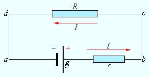
Figure 1.7.2.
Closed DC circuit.
Ohm's law for a complete circuit: the current strength in a complete circuit is equal to the electromotive force of the source divided by the sum of the resistances of the homogeneous and inhomogeneous sections of the circuit.
DIV_ADBLOCK19">
(R<< r), тогда в цепи потечет ток короткого замыкания
Short circuit current is the maximum current that can be obtained from a given source with electromotive force and internal resistance r. For sources with low internal resistance, the short circuit current can be very high and cause destruction of the electrical circuit or source. For example, lead-acid batteries used in automobiles can have short-circuit currents of several hundred amperes. Short circuits in lighting networks powered from substations (thousands of amperes) are especially dangerous. To avoid the destructive effects of such large currents, fuses or special circuit breakers are included in the circuit.
In some cases, to prevent dangerous values of short circuit current, some external resistance is connected in series to the source. Then the resistance r is equal to the sum of the internal resistance of the source and the external resistance, and when short circuit the current will not be excessively high.
If the external circuit is open, then Δφba = – Δφab = ɛ, i.e., the potential difference at the poles of an open battery is equal to its emf.
If the external load resistance R is turned on and current I flows through the battery, the potential difference at its poles becomes equal to Δφba = ɛ – Ir.
In Fig. 1.7.3 shows a schematic representation of a direct current source with an equal emf and internal resistance r in three modes: “idling”, load operation and short circuit mode (short circuit).

Figure 1.8.3.
Schematic representation of a direct current source: 1 – battery open; 2 – battery is closed to external resistance R; 3 – short circuit mode.
To measure voltages and currents in DC electrical circuits, special instruments are used - voltmeters and ammeters.
A voltmeter is designed to measure the potential difference applied across its terminals. It is connected in parallel to the section of the circuit on which the potential difference is measured. Any voltmeter has some internal resistance RB. To ensure that the voltmeter does not introduce a noticeable redistribution of currents when connected to the circuit being measured, it internal resistance must be large compared to the resistance of the section of the circuit to which it is connected. For the circuit shown in Fig. 1.7 4, this condition is written in the form: RB >> R1.
This condition means that the current IB = Δφcd / RB flowing through the voltmeter is much less than the current I = Δφcd / R1 that flows through the circuit section being tested.
Since there are no external forces acting inside the voltmeter, the potential difference at its terminals coincides, by definition, with the voltage. Therefore, we can say that a voltmeter measures voltage.
An ammeter is designed to measure current in a circuit. The ammeter is connected in series to the open circuit of the electrical circuit so that the entire measured current passes through it. The ammeter also has some internal resistance RA. Unlike a voltmeter, the internal resistance of an ammeter must be quite small compared to the total resistance of the entire circuit. For the circuit in Fig. 1.7.4 The resistance of the ammeter must satisfy the condition RA<< (r + R1 + R2),
so that when the ammeter is turned on, the current in the circuit does not change.
Measuring instruments - voltmeters and ammeters - come in two types: pointer (analog) and digital. Digital electrical meters are complex electronic devices. Typically, digital instruments provide higher measurement accuracy.

Figure 1.7.4.
Connecting an ammeter (A) and a voltmeter (B) to an electrical circuit
Serial and parallel connection of conductors.
Conductors in electrical circuits can be connected in series and in parallel.
When connecting conductors in series (Fig. 1.8.1), the current strength in all conductors is the same: I1 = I2 = I.

Figure 1.8.1.
Series connection of conductors.
According to Ohm's law, the voltages U1 and U2 on the conductors are equal to U1 = IR1, U2 = IR2.
The total voltage U on both conductors is equal to the sum of the voltages U1 and U2:
U = U1 + U2 = I(R1 + R2) = IR,
where R is the electrical resistance of the entire circuit. This implies:
In a series connection, the total resistance of the circuit is equal to the sum of the resistances of the individual conductors.
This result is valid for any number of conductors connected in series.
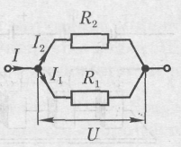
With a parallel connection (Fig. 1.8.2), the voltages U1 and U2 on both conductors are the same: U1 = U2 = U.

Figure 1.8.2.
Parallel connection of conductors.
The sum of currents I1 + I2 flowing through both conductors is equal to the current in an unbranched circuit:
This result follows from the fact that charges cannot accumulate at current branching points (nodes A and B) in a DC circuit. For example, charge IΔt flows to node A during time Δt, and charge I1Δt + I2Δt flows away from the node during the same time. Hence,
Writing based on Ohm's law:
![]()
where R is the electrical resistance of the entire circuit, we get:
When connecting conductors in parallel, the reciprocal of the total resistance of the circuit is equal to the sum of the reciprocals of the resistances of parallel-connected conductors.
This result is valid for any number of conductors connected in parallel.
Formulas for series and parallel connection of conductors allow in many cases to calculate the resistance of a complex circuit consisting of many resistors. In Fig. 1.8.3 shows an example of such a complex circuit and indicates the sequence of calculations.

Figure 1.8.3.
Calculation of resistance of a complex circuit. The resistances of all conductors are indicated in ohms (Ohm)
It should be noted that not all complex circuits consisting of conductors with different resistances can be calculated using formulas for series and parallel connections. In Fig. 1.8.4 shows an example of an electrical circuit that cannot be calculated using the above method.
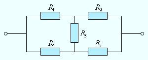
Figure 1.8.4.
An example of an electrical circuit that is not reduced to a combination of series and parallel conductors
Lesson No. 36-169 Connection of conductors. Ohm's law for a complete circuit. Electromotive force. D/z: 8.6; clause 8.7; clause 8.9
1. Connection of conductors.
1.1 Serial - compound, in which the end of the previous conductor is connectedwith the beginning of the next one.
For serial connection: I 1 = I 2 (if the current is constant, then during time t equal charges flow through any section of the conductor)
U = U 1 + U 2 (the work of electrostatic forces when moving a unit charge through sections 1 and 2 is equal to the sum of the work in these sections).
Equivalent conductor (resistance) is a conductor that replaces a group of conductors (resistance) without changing the currents and voltages in the section of the circuit under consideration.
According to Ohm's law: U
=
IR
,
those. U 1 =IR 1; U 2 =IR 2;  IR=IR 1 +IR 2 = I(R 1 +R 2), i.e. R= R
1
+R
2
or else R=
IR=IR 1 +IR 2 = I(R 1 +R 2), i.e. R= R
1
+R
2
or else R= 
Special case: R = nR ,
When connected in series, the equivalent resistance of the entirecircuit is equal to the sum of the resistances of individual sections of the circuit. Since I 1 =I 2; I 1 =  ; I 2 =
  ; then U 1 =I 1 R 1 and U 2 =I 2 R 2 therefore,
  =
=
When conductors are connected in series, the voltage acting on the conductors is directly proportional to their resistance.
Disadvantage: when the circuit of one of the series-connected consumers opens, the current disappears throughout the entire circuit (inconvenient in practice).
1.2 Parallel - connection, in which the beginnings of the conductors are connected into one node, and the ends into another.
 U=U 1 =U 2 ; I= I 1 =I 2 According to Ohm’s law:
  I=
I=  I 1
=
I 1
= ; I 2
=
; I 2
= ,
i.e. =
,
i.e. =  +
+
 =
=
 +
+
 or =
or =  ; q =q 1 + q 2
The conductivity of the entire branch (all parallel-connected conductors together) is equal to the sum of the conductivities of the individual branches (each parallel-connected conductor).
Special case: R 1 = R 2 =…=R n, then R
= ,
where n is the number of conductors with the same resistance.
,
where n is the number of conductors with the same resistance.
From the relations U 1 =U 2 ; U 1 =  ; U 2 =
  follows that
  =
= - when conductors are connected in parallel, the current strengths in the branches are inversely proportional to their resistances.
Advantage: if the voltage between nodes remains constant, then the currents in the branches are independent of each other
2. Ohm's law for a complete circuit
The complete chain contains:
 - outer area - current consumer, regulating, monitoring, etc. devices with a common resistance R
- internal area - current source with emf ε and with internal resistance r (the resistance possessed by the source electrical energy, since it is a conductor, the current generates heat in it).
Let us consider a closed circuit consisting of an external part having a resistance R and an internal part - a current source whose resistance r.
According to the law of conservation of energy, the emf of the current source is equal to the sum of the voltage drops across
external and internal sections of the circuit, since when moving along a closed circuit the charge returns to its original position - to a point with the same potential (i.e. φ A = φ B): ε = IR + Ir ,
Where IR and Ir - voltage drop on the external and internal sections of the chain. Hence Ohm's law for the complete circuit:
3.EMF The action of external forces is characterized by a physical quantity called electromotive force (EMF)
Electromotive force in a closed loop is the ratio of the work done by external forces when moving a charge along the loop to the charge: ε= 
If on batterywritten 1.5 V, then this means What outside forces (himic in this case) do 1.5 J work at moving a charge 1 C from one battery poles to another. Direct current cannot exist in a castle a broken chain, if there is no act outside forces i.e. there is no EMF.
EMF, like current strength, is an algebraic quantity. If EMF promotes the movement of positive charges in
 in the chosen direction, then it is considered positive (ε > 0). If the EMF prevents the movement of positive charges in the chosen direction, then it is considered negative (ε
It should be borne in mind that this formula can only be used when the current flows inside the source from the negative pole to the positive, and in the external circuit from positive to negative.
3. Connection of electrical energy sources into a battery.
 3
3 .1. Serial connection. The “+” pole of the previous source is connected to the “-” pole of the subsequent one. Ohm's law for the entire circuit in series connection. I =
3.2. Parallel connection. The "+" pole is connected to one terminal,
and the “-” pole goes to the other. Ohm's law for the entire circuit in parallel
 connection: I =
3.3 Mixed connection. Ohm's law for the entire circuit with a mixed connection:
I = 
 Exam questions
 A. 1.2 Ohm B. 5.2 Ohm C. 5 Ohm
 A. 1.2 Ohm B. 5.2 Ohm C. 5 Ohm
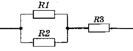
If R 1 =2 Ohm, R 2 =3 Ohm, R 3 =4 Ohm A. 1.2 Ohm B. 5.2 Ohm C. 5 Ohm
31. What physical quantity is determined by the ratio of the work done by external forces when moving a charge q throughout a closed electrical circuit to the value of this charge?
A. Current strength. B. Voltage. B. Electrical resistance. D. Electrical resistivity. D. Electromotive force.
32.Which of the following formulas expresses Ohm's law for a complete circuit?
A.I =
; B.I =
 ; IN.IUΔt; G.P=
UI; D.ρ
=
ρ
0
(1+αt).
; IN.IUΔt; G.P=
UI; D.ρ
=
ρ
0
(1+αt).
33. A current source with an emf of 18 V has an internal resistance of 30 Ohms. What value will the current have when connecting a resistor with an electrical resistance of 60 ohms to this source?A. 0.6 A. B. 0.3 A. C. 0.2 A. D. 0.9 A.D. 0.4 A.
Tasks
№ 1. Galvanic cell with an EMF of 5.0 V and an internal resistance of 0.2 Ohm is connected to a conductor with a resistance of 40.0 Ohm. What is the voltage U?
on this conductor?
1. Galvanic cell with an EMF of 5.0 V and an internal resistance of 0.2 Ohm is connected to a conductor with a resistance of 40.0 Ohm. What is the voltage U?
on this conductor?
№ 2 V network with a voltage of 220 V, two electrical lamps
resistance 200 Ohm each. Determine the current passing through each lamp.
№ 3 Find the total resistance of the section of the circuit shown in the figure,
If R 1 =20 Ohm, R 2 =R. 3 =R 4 =15 Ohm, R 5 =3 Ohm, R 6 =90 Ohm.
№ 4. Four resistors of 60 ohms each are given. Draw connection diagrams for all four resistors so that the total resistance is equal to, respectively: 15, 45, 60, 80, 150 and 240 Ohms. Next to each diagram write a calculation of the total resistance.
№ 5. The emf of the electrical energy source is 100 V. With an external resistance of 49 Ohms, the current in the circuit
2 A. Find the voltage drop inside the source and its internal resistance.
№ 6. The potential difference at the terminals of an open current source is 4 V. Determine the internal resistance of the current source if, with resistance external area 4 Ohm circuit current is 0.8 A.
№ 7. A current source with an emf of 220 V and an internal resistance of 2 Ohms is closed by a conductor with a resistance of 108 Ohms. Determine the voltage drop inside the current source.
№ 8. Determine the EMF and internal resistance of the current source if, with an external resistance of 3.9 Ohms, the current in the circuit is 0.5 A, and with an external resistance of 1.9 Ohms, the current is 1 A.
№ 9. Determine the current strength during a short circuit of a battery with an emf of 12 V, if when it is shorted to an external resistance of 4 Ohms, the current strength in the circuit is 2 A. Why during a short circuit the voltage drop on the external section of the circuit is close to zero, although in this case in circuit has the greatest current?
№ 10. The emf of the current source is 220 V, the internal resistance is 1.5 Ohms. What resistance should be taken in the external section of the circuit so that the current strength is 4 A?
 (1 ratings, on average: 5,00 out of 5)

