Direct and alternating current designation. Physical quantities of electric current
Posted on 13.09.2016 08:48 - miniature instrument, designed to measure various electrical parameters, as well as to test semiconductor devices and electronic components. Roughly speaking, a multimeter is the same measuring instrument as a ruler or, for example, scales, only it measures not centimeters and grams, but Ohms, Volts and Amps. By the way, the fact that it can measure several quantities is evidenced by the prefix "multi".
If we have two mutually inductive windings and feed one of them into alternating current. exits the emitter to the base. No matter where they are. Attention. second winding. The bipolar junction transistor consists of three layers of semiconductor materials. The magnitude of the induced voltage in secondary winding is equal to the product of the value of the primary voltage and the ratio of the number of revolutions in the secondary winding and the number primary windings: transistor. control.
The base current drives the transistor. magnetic flux allows you to accumulate a certain "inertia" of the movement of electrons through a conductor that creates a field. Electron inertia. Although the electrical flow between two conductors allows the accumulation of free electrons inside these conductors. as in the case of electric fields arising between electrically charged particles. in accordance with current law Kirchhoff. magnetic ones can occupy space between bodies and can affect matter at a distance. called the nucleus.
The appearance of the device is shown in the photo. As you can see, it has a large switch on its front panel. With its help, the parameter is selected, as well as the measurement limit. In addition, the multimeter has a liquid crystal display, which displays the measurement result. About, how to use a multimeter will be discussed in this article.
Some coil windings are made around a certain type of material. This is the first and most important rule transistors: all currents must flow in the correct direction for the device to work as a current regulator. and the movement of electrons occurs all the time against the direction of the arrow. and flow through the collector is not possible. the control current and the controlled current are fully summed at the emitter. How electric fields. it behaves like a closed switch and allows a proportional current to pass through the collector.
The emitter current is the sum of the base and collector currents. This shape maintains a magnetic field stronger than that of a single stream. because they are the only currents passing through these terminals. Definition Coils are specially designed components. In other words. in the form of a winding of conductive material. regardless of the magnitude of the voltage drop across the collector. Magnetic fields change the alignment of an electron with atoms and can lead to physical forces between atoms.
In fairness, it should be noted that the indication in the multimeter is not necessarily liquid crystal. The market still sells many outdated models with an arrow scale. And although these devices are not as accurate as digital ones, and they are not as convenient to use, many radio amateurs prefer them. And yet, in this article we will focus on devices with liquid crystal display.
When there is no current through the base. and the controlled current is called the collector current. the control current is called the base current. As you can see. There are two types of load carriers. This effect is called electromagnetism. the transistor behaves like an open switch. through free space between them.
The collector current is limited by the base current. use the phenomenon of electromagnetism. The higher the current value across the coil. The newer symbol for the coil is no longer the actual coil. Due to the fact that the coils store the kinetic energy of the electrons moving through the coil magnetic field. All of these design choices ultimately affect the performance and characteristics of the reels. the behavior of these devices is very different from the behavior of resistors in a circuit. such as a capacitor. and this magnetic flux represents storage kinetic energy due to the displacement of electrons by winding. rectangular.
All multimeters, without exception, allow you to measure voltage, current and resistance. These values will be discussed in more detail below. In addition, most devices are equipped with a circuit probe, some multimeters have the ability to measure temperature. The circuit probe allows you to quickly establish the integrity of the conductor. In the event that the circuit resistance is less than 30 ohms, a beep will sound. This is very convenient - there is no need to look at the indication, and the resistance value, when checking an elementary circuit, is not so important.
Because the inherent resistance of any normal conductor is sufficient to quickly dissipate power in the circuit and reduce current. transfer the stored energy to the coil. and this change in the strength of the field also causes a voltage drop according to the principle of electromagnetic induction. when there is no power source in the circuit. Load the coil. and this change in the magnetic field spontaneously induces a voltage drop of opposite polarity. electrons that are at rest in the coil, as a rule, remain at rest.
In theory. In other words. it "resists" variation by creating a tension in its polarity opposite to its change. the current through it should increase. This means that the magnetic field must also decrease in strength. the current through it should drop. we can define the tendency of a coil to resist a change in current as follows: Electrons moving through a coil tend to stay in motion. coils tend to resist changes in current. The ability of a coil to store energy in accordance with the current means the tendency to constantly maintain the current flowing through it.
Another one useful feature multimeters - checking semiconductor diodes. Anyone who has worked with them knows that a diode passes current in one direction. If there is conductivity in another, then the device is faulty. The multimeter analyzes these parameters and displays the result on the screen. In addition, in the case when there is no marking on the body of the diode, using a tester, you can easily determine its polarity. Unfortunately, given function Not all multimeters have one.
When the current value through the coil increases or decreases. coil as a load. the ability of a coil to individually maintain current at its terminals can only be achieved with superconducting wires. Energy storage and release To store energy in a coil.
Inductance. A measure of the capacity of an energy storage coil for given value current is called inductance. behavior is like a source of power. the behavior is similar to the task. coil as a source of energy When the current through the coil decreases. and the unit of measure is Henry. this will result in a voltage drop in the opposite direction of electron movement. because the energy supply is decreasing. abbreviated H. Observe the polarity of the voltages in the direction of the current. we say that the coil is loaded.
More expensive and advanced models of devices have the ability to measure such quantities as the inductance of coils and the capacitance of capacitors. But since only special multimeters can do this, they will not be considered in this article.
In this section, a small educational program for those who were not previously familiar with these quantities. It is immediately worth noting that special values \u200b\u200bare invented for their measurement. If we draw an analogy with distance, then it will be measured in meters and denoted English letter"m". Exactly the same abbreviations were invented for electrical quantities.
In this situation. In this situation. as the energy stored in the form of a magnetic field increases. Inductance measures the intensity of resistance to current oscillations. Unload the bobbin. we say that the coil is unloaded. Observe the polarity of the voltage drop from the direction of the current. an increasingly powerful magnetic field will be created, absorbing energy from the source. When the current through the coil increases. the coil will initially resist the electrons, producing a voltage drop equal to the source voltage drop.
Maybe. output to the external circuit. Note. As the current starts to increase. How does the coil store more energy. the arrows indicate the actual movement of electrons through the diode. depending on the polarity of the applied voltage. the current through it increases. Note that this behavior is exactly the opposite of a capacitor. The principle of a capacitor is exactly the opposite of a coil, and coils store energy by maintaining current through their windings. or he will block it.
Voltage is the force that causes current to flow through a conductor. The higher the voltage, the faster the electrons move. Voltage is usually measured in volts, abbreviated to a capital letter "V". But since it is impossible to find a multimeter with a Russified front panel on the market, you need to look for the English “V” on it.
The intensity of current flow through an electrical circuit is determined by its strength. Here it is appropriate to use the plumbing analogy to imagine an electrical circuit in the form of a pipe filled with water. High pressure in this pipe is not yet a reason for water to flow through it. Maybe at the other end of the pipe the valve is simply closed. And as it opens, the flow rate will increase. This speed, in an electric circuit, will be the current strength. It is measured in amperes "A".
Connecting to a circuit When connecting to a simple circuit. except for the capacitor and coil. Factors of influence and inductance formulas. Definition of diodes. diode is electronic device, which allows the flow to flow in only one direction. where storing energy results in an increase in voltage drop across a single component! Capacitors store energy by maintaining static voltage between its fittings. and the voltage drop across its terminals is minimal. The main element in an electrical circuit. consisting of a battery and a lamp.
His growth stops. the coil no longer absorbs energy from the source. although there are other technologies. The most used diode in electronic circuits is a semiconductor. In this moment. Capacitive. The diode either passes current through the lamp. If this voltage gets too high. We can think of a diode as a switch: "closed". Breakthrough voltage increases with temperature and decreases as temperature decreases. in fact there is a small amount of drain current passing through the diode even with reversed polarization.
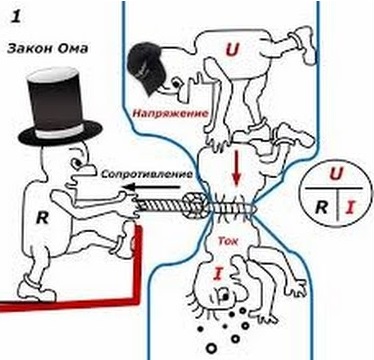
Resistance shows how difficult it is for current to pass through a particular section of an electrical circuit. Returning to the plumbing allegory, resistance can be compared to some kind of narrow pipe section, such as a blockage. The smaller the diameter of the pipe in this place (read more resistance), the less speed water flow (current). This is very well illustrated in a hilarious picture. The unit of measurement is the ohm, which is denoted Greek letter omega (?).
Bursting Voltage A diode cannot sustain an infinitely high inversion polarization voltage. However, reverse flow can be ignored for most applications. Direct polarization When the polarity of the battery is such that the electron passes through the diode. and this current is called reverse current. Simplified diode equation where.
Reverse rotation of polarization. does not allow current to pass through it due to the expansion of the drain zone. we say that the diode polarizes inversely with the forward polarization voltage. The alternative voltage source is only "taken" by the load once every half cycle. Drawbacks for most power applications. Single pole rectifier The simplest circuit rectifier is a monovariable rectifier. Recovery is the conversion of AC to DC. This allows only one half of the AC waveform to be transmitted from the source to the load.
direct current For those who know English, it will not be difficult to translate. Literal translation, directed current. This electricity that flows in one direction. In Russian, he received the name permanent. Most small household appliances run on direct current. It is issued by batteries of all classes and sizes, car and telephone batteries. Direct current is given the abbreviation DC.
The symbol for alternating current, that is, the current generator, is as follows. AC resistor circuit. . Ohm's law for this case. A circuit with an ideal coil powered by alternating current. . The coil consists of a threaded conductor. We call the ideal spool the spool that cancels the residency of the thread from which it is formed.
Because the coil switches alternating current, an alternating magnetic field is created around it, therefore an alternating magnetic flux. Thus, an inductive current appears through the coil. Because of this, the voltage measured at the ends of the bobbin is canceled out by the current flowing at an angle.
Depending on the manufacturer on the multimeter, the corresponding positions may be indicated either DCA And DCV(measurement of direct current and voltage, respectively), or “A” and “V”, and next to the line and below it is a dotted line.
Alternating current ( alternating current) changes its direction dozens of times per second. For example, in home outlets, the frequency is 50 hertz. This means that the direction of the current changes 50 times per second. But you should not, without experience and knowledge of safety precautions, try to measure the high voltage in the outlet. It is very dangerous.
Ohm's law for ideal coil. It is called inductive reactance and is the resistance of an ideal AC coil. The capacitor circuit is powered by alternating current. . If in direct current the capacitor is charged only electric charges on two armatures that become positive and negative, and the circuit is not closed, then in alternating current electrical circuit closes because the currents are moving.
These changes in the meaning of the field when the current circuit is closed by a capacitor. In the case of AC capacitors, the voltage is disconnected from the current by an angle. Ohma's condenser law. It's called capacitive. reactance and is the capacitance created by the capacitor operating on alternating current.
Alternating current has received the abbreviation "AC". There are 2 options on the multimeter switches:
“ACA" And " ACV” measurement of AC current and voltage; A ~ and V ~.
Measuring direct voltage has its own nuances - be sure to observe the polarity. This is especially true for pointer devices. In this case, their measuring head may fail. Digital - endure it painlessly, just a minus sign appears on the screen. This must be taken into account before using the multimeter in voltage measurement mode.
The resistor circuit, coil and capacitor are powered by AC. Being connected in series, these consumers pass through the same current intensity. Ohm's law for a part of an alternating current circuit. Here are the following situations. From the phasorial representation of the resonant circuit can be written.
Real coil powered by alternating current. A true coil is one to which we do not neglect the resistance of the coil that forms the coil. Ohm's law for a real coil. Battery inverters are usually unidirectional and provide the conversion of DC power from battery terminals to AC power for consumers.
When working with a multimeter, it is very important to know how to connect it when measuring. There are only two options: in series or in parallel, depending on what value needs to be measured. When connected in series, the same current flows through all elements of the circuit. Therefore, in series, they also say “into a circuit break”, you need to measure the current strength. If we consider parallel connection, then here the same voltage is applied to each element, and becoming probes parallel to any of them, you can measure it. So, voltage is measured in parallel, current is measured in series, this must be remembered and never confused.
The figure shows the circuits of parallel and serial connection. It should be noted that in series, the current flowing through each of the elements will be the same if their resistances are equal. The same condition will equal voltage through the elements, in case of parallel connection.
Not an experienced user, tricky symbols printed on the main switch of the multimeter. But there is nothing complicated here, just remember how the units of measurement of voltage, current and resistance are indicated:
- Volt - "V";
- Ampere - "A";
- OM - "Ω"
All manufacturers, without exception, use only these icons. True, there is one but. It is not always necessary to measure integer values. Sometimes the result is thousandths of a unit of measurement, and sometimes, on the contrary, millions. Therefore, the corresponding measurement limits are included in the multimeter and manufacturers use metric prefixes to designate them. There are only four main ones:
- µ (micro) - 10-6 units;
- m (miles) - 10-3 units;
- k (kilo) - 103 units;
- M (mega) - 106 units.
These prefixes are added to the main units of measurement and in this form are applied to the switch of the device operation modes: µA (microampere), mV (millivolt), kOhm (kiloohm), mOhm (megaohm).
Before measuring any value, you need to set the appropriate limit. To do this, you need to at least approximately know what the result will be, and set a number slightly higher than it on the device. If even in the first approximation it is impossible to predict the value of the measured current or voltage, it is better to start from the maximum limit. The result will be very approximate, but will allow you to draw a conclusion about how to set the limit. Measurements can now be taken with greater accuracy.
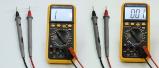
Some multimeters are equipped with an “auto-rangin” feature. Thanks to it, the measurement limit is set automatically. This is very convenient, since using a multimeter, in this case, is much easier. The figure shows a simple multimeter (left) and a device equipped with an auto-ranging” function (right).
Instrument manufacturers rarely, if ever, adhere to standards, so the same function may be labeled differently on different multimeters. Of course, it is impossible to list everything here. possible options characters, but the main ones are listed below.
So, a wavy line represents alternating current. And note that both current and voltage can be measured. It can be alternating current (current strength), or it can be alternating current voltage.
![]()
The horizontal line, with a dotted line below it, denotes D.C. and constant voltage.
![]()
Designation of current and voltage using the abbreviation “AC” and “DC”. The example shows that sometimes letters are duplicated by signs. It should also be noted that the designations AC, DC can be either before A or V, or after.
This icon indicates the continuity of the chains. If the circuit is intact, the multimeter will beep. Sometimes this function is combined with the resistance measurement mode. In this case, the beep will sound if the resistance is less than 30 ohms.
![]()
Diode test function. Allows you to determine the health of the diode and its polarity.
![]()
to measure voltage, you need:
- connect the probes to the multimeter.
- better right away, get used to doing it right: black to the nest COM and red to the nest V;
- set the switch to the position corresponding to the measurement mode (variable or constant) and the limit;
- now you can become probes in parallel with the circuit element on which it is supposed to measure the voltage.
The figure shows an example of measuring the voltage drop on a nine-volt battery "krone";
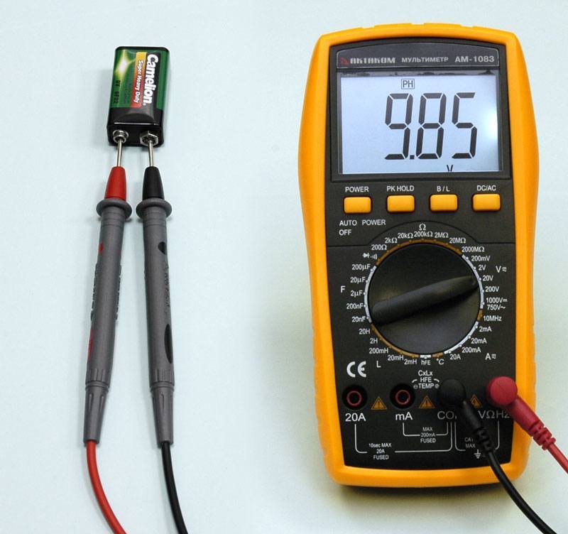
Now the screen of the device should show voltage. In the event that the display shows "1", the measurement limit is small, you need to set it smaller. But in this example toggle is in correct position, set to a limit of 20 volts DC. The red wire is positive, it is connected to the plus of the battery, and the black one, respectively, is a minus, inserted into the connector COM on a multimeter. It connects to the battery negative.
We connect the probes, do not forget about the color; Here you need to pay attention to the following: when measuring low currents, the red cord is connected to the same socket as when measuring voltage, and currents up to 10 amperes - to the “10A” connector.
Now you need to select the measurement mode and its limit.
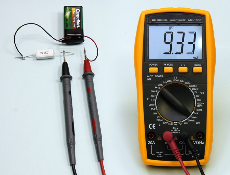
Unlike voltage, current is measured sequentially. To do this, you have to break (that's why they say "break") the chain. If everything is done correctly, the display will show the current value. In the event that zeros are displayed on the screen, there may be several reasons: the voltage is not turned on, there is no contact on the probes, and, most likely, the limit is large. If the unit is displayed on the screen, the limit is small. The figure shows a circuit for measuring direct current flowing through a light bulb.
Connect the probe to the “COM” and “?” connectors. Of course, it is not necessary to observe the polarity here, and yet it is better to connect black to the COM connector. Set the limit and measurement mode.
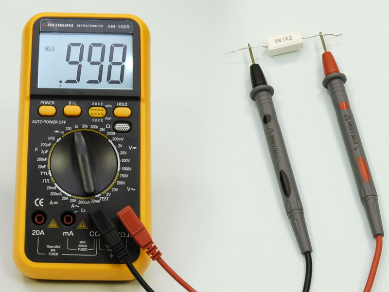
We measure the resistance of the resistor or the spiral of the light bulb, as shown in the figure. It must be borne in mind that the measured element must be excluded from the circuit. Otherwise, the measurements will not be correct. If the indicator in front of the figure shows several zeros, the measurement limit was taken, for greater accuracy it must be reduced. If the limit is small, the indicator will still show the same unit.
Set the device to mode sound signal. There is a corresponding icon on the switches. It is also shown as an example in the table above.
Install the probes in the sockets by analogy with measuring resistance. Measure desired element scheme. If an electric current flows between the probes, i.e. it is working, a sound signal with a frequency of about 1 kHz should be heard. in this case, it is necessary to disconnect the power supply from the circuit. By the way, if there is no sound signal, then it is not at all necessary that it is faulty. Perhaps its normal resistance exceeds 30 ohms.
A multimeter tests a diode by passing current through it and measuring the voltage drop across it. With some skill, the device can even check bipolar transistors. Sometimes semiconductor devices do not even need to be soldered from the circuit. So, the sequence of actions is as follows.
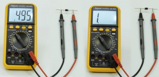
The probes are connected in the same way as measuring resistance. The device switch is set to measure the diode. Most often, this icon is a schematic designation of a diode. We measure the diode by touching its anode and cathode with probes. The readings of the device should be: for a silicon diode -500-700 mV, for a germanium diode - 200-300mV, a working LED should show 1.5-2 V.
Now we change the polarity on the diode. The device should show zeros, otherwise it is faulty. That, in general, is all that can be briefly told about working with a multimeter. Everything else will come with experience. The main thing is not to forget about safety and before using a multimeter, be sure to study the safety rules.
Among the types of electric current, there are:
D.C:
Designation (-) or DC (Direct Current = direct current).
Alternating current:
Designation (~) or AC (Alternating Current = alternating current).
In the case of direct current (-), the current flows in one direction. Direct current is supplied, for example, by dry batteries, solar panels and accumulators for appliances with low current consumption. For the electrolysis of aluminum, in electric arc welding and in the operation of electrified railways direct current required great strength. It is created using AC rectification or using DC generators.
As the technical direction of the current, it is assumed that it flows from the contact with the “+” sign to the contact with the “-” sign.
In the case of alternating current (~), a distinction is made between single-phase alternating current, three-phase alternating current and high-frequency current.
With alternating current, the current constantly changes its magnitude and its direction. In the Western European power grid, the current changes direction 50 times per second. The frequency of oscillation changes per second is called the frequency of the current. The unit of frequency is hertz (Hz). Single-phase alternating current requires a voltage-carrying conductor and a return conductor.
Alternating current is used on the construction site and in industry to work electrical machines, such as hand-held grinders, electric drills and circular saws, as well as for building site lighting and building site equipment.
Three-phase alternators generate on each of their three windings AC voltage frequency 50 Hz. Three separate networks can be supplied with this voltage, and at the same time, only six wires can be used for direct and return conductors. If you combine the return conductors, then you can limit yourself to only four wires
The common return wire will be the neutral conductor (N). As a rule, it is grounded. The other three conductors (outer conductors) are abbreviated LI, L2, L3. In the German power grid, the voltage between the outer conductor and the neutral conductor, or earth, is 230 V. The voltage between the two outer conductors, for example between L1 and L2, is 400 V.
High-frequency current is said to be when the oscillation frequency is much higher than 50 Hz (from 15 kHz to 250 MHz). High-frequency current can be used to heat conductive materials and even melt them, such as metals and some synthetic materials.
 (1 ratings, on average: 5,00 out of 5)

