Short circuits on a line with one-sided power supply due to phase loss
The invention relates to the field of electrical engineering. The technical result is to provide protection for long lines along their entire length. This result is achieved by using natural indicator actual decrease in load current in the line as consumers move away from the supply substation. Having installed additional control short circuit current and the actuator cutting the line at the point where the resistance of the phase-zero loop begins to exceed the permissible value for tripping the circuit breaker releases installed in the KTP switchgear (complete transformer substation), it is possible to match the load, the settings of the actuator and the magnitude of the short circuit current at this point. Thus, the claimed method makes it possible to provide reliable protection long line from short circuits along its entire length.
The method of protecting long rural power lines-0.4 kV from short circuits relates to the field of electrical engineering, and more precisely to methods and methods for protecting electric lines, and can be used to protect against short circuits for both new and existing power lines-0, 4 kV. The roots of the problem of long rural power lines come from the natural process of rural expansion. Existing lines are being extended. The probability of short circuits and especially single-phase ones is quite high, since each branch to residential building has no protection. Traditional way protection is the control of short circuit currents by means of a circuit breaker in the switchgear of a package transformer substation. The machine has thermal and electromagnetic releases. The rated current should be 20-30% greater than the total design load all consumers per phase. Therefore, its protection settings are often beyond the limits of sensitivity during a short circuit in long lines due to the fact that the resistance of the line wires at some distance from the transformer substation begins to exceed the permissible resistance of the phase-zero loop. In this case, the short circuit current becomes less than the current sufficient to trigger the circuit breaker. The line is not disconnected during a short circuit with all the ensuing consequences. There are cases of wires welding together, one of the wires burning out and falling to the ground, which is especially dangerous for children and animals. At industrial enterprises where there are electrical laboratories, electrical measurements of the phase-zero loop are regularly carried out according to an established schedule in order to identify electrical equipment that is not protected against short circuits. For this purpose, there are appropriate instruments and measurement methods. If the electrical equipment is not turned off in time during a short circuit, then a fire hazardous situation arises, which, of course, is unacceptable. The single-phase short circuit current is 1.73 times less than the current line current short circuit, therefore it is also possible to use UNZ zero protection devices, designed to protect a 0.4 kV line from single-phase short circuits. Neutral wire passed into the hole of the differential transformer. If a single-phase short circuit occurs the device generates a shutdown signal that affects independent release feeding machine. This method allows you to reduce the current protection setting, but in this case the response threshold must be greater than the total load current in order to exclude false alarm protection. The short circuit current at the end of a long line may still be less than the protection setting, and it will not work, which often happens. This means that to solve the problem of long lines, a fundamentally different approach is needed. The key to solving this problem is that it is not at all necessary and even unreasonable to disconnect the entire line if a short circuit occurs at the end of the line (!).
The present invention provides a simple method to solve this problem. To explain the method, practical example one rural line. Rural KTP-400, one of the three lines of which is 800 meters long. A 250 amp circuit breaker is designed to protect this line from short circuits. The electromagnetic cut-off has a multiple of 12, and the thermal release accordingly rated current machine 250 ampere. A 0.4 kV power line wire has a cross-section of 50 square millimeters, the resistance of which is 0.63 ohms per 1000 meters of length. To calculate the phase-zero loop R=:=:=0.012 ohm.
For reliable operation, the operation current of the electromagnetic release must be less than the short circuit current, that is, the loop resistance should not exceed: R=Un:=220:=0.073 ohm. Let us determine the distance from the substation, beyond which electromagnetic release will no longer work, since the resistance of the phase-zero loop will begin to exceed 0.073 ohm: R=0.073-0.012=0.061 ohm, divide by 2, since there are two wires in the loop circuit: 0.061:2=0.0305 ohm. Let's make up the proportion of distance and wire resistance: 1000 to 0.63 as L to 0.0305, that is: L=1000×0.0305:0.63=49.2 m What happens? Already at a distance of 50 meters from the beginning of the line, the machine’s cutoff will be inactive! But there is also a thermal release in the machine. To trigger thermal release with a minimum delay we will determine the boundary distance at 2 times the short circuit current in relation to the thermal release current: R=220:=0.44 ohm; 0.44-0.012=0.428 ohm; 0.428:2=0.214 ohms. By analogy with how the proportion is composed above, we determine the distance from the transformer substation for the thermal release:
L=1000×0.214:0.63=339.7 m. That is, at this distance from the package transformer substation, the protection effect by means of a circuit breaker installed in the substation switchgear ends. But what about the remaining 460 meters of the line and its consumers? Of course, this is unacceptable. More than half the length of the power line actually has no protection against short circuits.
The proposed method in this invention simply solves this problem. As mentioned above, it is not necessary to disconnect the entire line if a short circuit occurs at the end of the line. Therefore, at the point where protection by the first machine ends, another one is cut into the line circuit breaker, which carries only the remaining load, which means that its release settings already correspond to the resistance of the phase-zero loop at this point. Let us determine at what distance the line is now protected. In accordance with the remaining load, we select a 160-amp machine. We calculate similarly to the calculations above: 220: = 0.69 ohm. 0.69-0.012=0.678 ohm. 0.678:2=0.339 ohm. L=1000×0.339:0.63=538.1 m. But since our line is 800 meters long, it is necessary to do the same in accordance with the load at this point. Now we select a 100 amp machine. We determine the distance from the transformer substation provided with protection now: 220: = 1.1 ohm. 1.1-0.012=1.088 ohms. 1.088:2=0.544 ohms. L=1000×0.544:0.63=863.5 meters. Thus, a 0.4 kV power line is protected against short circuits along its entire length.
A sealed power box is installed directly on the support where the machine is to be embedded into the line. The proposed protection can be implemented both for new power lines and for existing lines. The location and point of insertion of the machine into the line is determined using existing instruments for measuring the phase-zero loop or by simply measuring the magnitude of the voltage drop across a known load (ammeter-voltmeter method). The costs are insignificant compared to the resulting reliability of protecting 0.4 kV lines from short circuits.
Thus, in order to ensure line protection along its entire length through the use of an indicator of the actual decrease in load current in the line as consumers move away from the supply substation, it additionally has control of phase currents and an actuator cutting the line with releases corresponding to the load and short circuit current exactly at the point , where the resistance of the phase-zero loop begins to exceed the permissible resistance for the operation of the first device.
A method for protecting long rural power lines of 0.4 kV from short circuits, based on monitoring the current value in phase wires line and the impact on the line shutdown mechanism with a short circuit current exceeding the operating settings of the electromagnetic and thermal releases, characterized in that, in order to ensure protection of the line along its entire length through the use of an indicator of the actual decrease in the load current in the line as consumers move away from the supply substation , additionally has control of phase currents and a line-cutting actuator with releases corresponding to the load and short-circuit current precisely at the point where the resistance of the phase-zero loop already begins to exceed the permissible resistance for operation of the first device.
Causes of short circuit
Main reason short circuit– violation of insulation of electrical installation equipment, including cable and overhead power lines. Here are a few examples of short circuits occurring due to insulation failure.
When conducting earthworks the high-voltage cable was damaged, which led to a phase-to-phase short circuit. In this case, the insulation damage occurred as a result of mechanical impact on the cable line.
A single-phase ground fault occurred in an open switchgear of a substation as a result of a breakdown of the support insulator due to the aging of its insulating coating.
Another fairly common example is a branch or tree falling on the wires of an overhead power line, which leads to the wires snapping or breaking.
Methods for protecting equipment from short circuits in electrical installations
As mentioned above, short circuits are accompanied by a significant increase in current, which leads to damage to electrical equipment. Consequently, protecting electrical installation equipment from this emergency mode is the main task of the energy sector.
To protect against short circuits as an emergency operation of equipment, various protective devices are used in electrical installations of distribution substations.
The main purpose of all relay protection devices is to open the circuit breaker (or several) that supply the section of the network where the short circuit has occurred.
In electrical installations with a voltage of 6-35 kV, overcurrent protection (MCP) is used to protect power lines from short circuits. To protect 110 kV lines from short circuits, phase differential protection is used as the main line protection. In addition, to protect 110 kV transmission lines, distance protection and earth protection (TZNP) are used as backup protections.
3Electricity transmission
Electricity transmission from power plants to consumers is one of the most important tasks of the energy sector. Electricity is transmitted primarily by air power lines(power lines) alternating current, although there is a tendency towards increasingly widespread use cable lines and DC lines. Necessity of P. e. over a distance is due to the fact that electricity is generated by large power plants with powerful units, and is consumed by relatively low-power electrical receivers distributed over a large territory. work depends on the distance unified electric power systems covering vast territories.
One of the main characteristics power transmission is its throughput, that is, the greatest power that can be transmitted along power lines, taking into account limiting factors: maximum power under stability conditions, corona losses, heating of conductors, etc. The power transmitted along AC power lines is related to its length and voltage dependence
Where U 1 And U 2 - voltage at the beginning and end of the power line, Z c is the characteristic impedance of the power line, a is the phase change coefficient characterizing the rotation of the voltage vector along the line per unit of its length (due to the wave nature of the propagation of the electromagnetic field), l- length of power lines, d- the angle between the voltage vectors at the beginning and end of the line, characterizing the power transmission mode and its stability. The maximum transmitted power is achieved at d= 90° when sin d= 1. For overhead AC power lines, it can be approximately assumed that the maximum transmitted power is approximately proportional to the square of the voltage, and the cost of constructing a power line is proportional to the voltage. Therefore, in the development of power transmission there is a tendency to increase voltage as the main means of increasing bandwidth Power lines.
In power transmission direct current There are no many factors inherent in AC power transmission that limit their capacity. The maximum power transmitted via DC power lines is greater than that of similar AC power lines:
Where E V - rectifier output voltage, R å - the total active resistance of the power transmission, which, in addition to the resistance of the power line wires, includes the resistance of the rectifier and inverter. The limited use of DC power transmission is mainly due to the technical difficulties of creating effective, inexpensive devices for converting alternating current into direct current (at the beginning of the line) and direct current into alternating current (at the end of the line). DC power transmission is promising for connecting large power systems remote from each other. In this case, there is no need to ensure the stability of these systems.
The quality of electricity is determined by reliable and stable work power transmission, which is ensured, in particular, by the use of compensating devices and automatic regulation and control systems (see. Automatic excitation control, Automatic voltage regulation, Automatic frequency regulation).
As a result of the research work, the following were developed:
direct current power transmission schemes that allow the most rational use of the design features of three-phase alternating current overhead lines intended for transmission electrical energy on three wires;
methodology for calculating the operating voltage of direct current for overhead power lines built on the basis of standard designs of three-phase alternating current poles of voltage classes 500-750 kV;
a methodology for calculating the capacity of overhead lines of three-phase alternating current with an operating voltage of 500-750 kV after their conversion to direct current according to the schemes proposed by the author;
a method for calculating the reliability of three-phase alternating current overhead lines with an operating voltage of 500-750 kV after their conversion to direct current according to the schemes proposed by the author.
A calculation has been made of the critical length of the line, starting from which direct current power transmission according to the schemes developed by the author will be more economically profitable than alternating current power transmission with a voltage of 500, 750 kV.
Based on the results of scientific research, recommendations are formulated:
by choosing the type of suspended disc insulators included in the insulating suspensions of overhead DC power lines;
by calculating the creepage distance of insulating suspensions of overhead DC power lines;
on the choice of a three-wire power transmission circuit, in relation to overhead direct current lines, made on the basis of standardized designs of three-phase alternating current supports;
on the use of standardized designs of three-phase alternating current supports on overhead direct current lines;
to determine the operating voltage of direct current, in relation to overhead direct current power lines made on the basis of standardized designs of three-phase alternating current supports;
for calculating the capacity of a three-wire DC power line.
The results of the calculations show that the capacity of existing three-phase alternating current power lines can be significantly increased by converting them to direct current electricity using the same supports, garlands of insulators and wires. The increase in transmitted power in this case can range from 50% to 245% for a 500 kV overhead line and from 70% to 410% for a 750 kV overhead line, depending on the brand and cross-section of the wires used and the installed capacity of the AC overhead line. Converting existing three-phase alternating current lines to direct current according to the proposed schemes will also significantly improve their reliability indicators. At the same time, the use of the developed circuits will increase reliability by 5-30 times, depending on the voltage class of the overhead line. In the case of a new design of DC overhead lines according to the above schemes, their reliability indicators will be equivalent.
In general, the possibility of converting existing overhead lines to three-phase alternating current is quite feasible. Such a technical solution may be relevant for increasing the capacity of overhead lines in operation while maintaining their configuration, and will also expand the scope of application of DC power transmission. The possibility of constructing new DC power lines using standardized designs of three-phase AC poles cannot be ruled out.
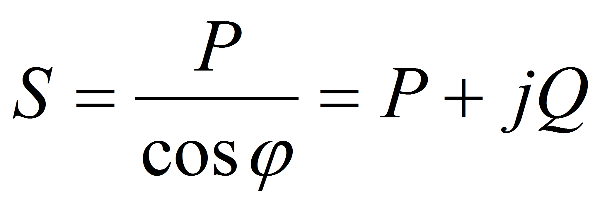
4 Reactive power – component of total power, which, depending on the parameters, circuit and operating mode of the electrical network, causes additional losses of active electrical energy and deterioration in the quality of electrical energy.
Reactive electrical energy – technologically harmful circulation of electrical energy between power sources and receivers of alternating electric current caused by electromagnetic imbalance of electrical installations.
The main consumers of active power V electrical systems ah are transformers, overhead electrical lines, asynchronous motors, valve converters, induction electric furnaces, welding units and other loads.
Reactive power can be generated not only by generators, but also by compensating capacitor devices, synchronous compensators or statistical reactive power sources (RPS), which can be installed at substations of the electrical network.
To normalize reactive power flows, when solving problems of reactive power compensation using our own resources and the efforts of consumers, to advance the process of solving problems of reactive power and tasks of optimizing its flows, normalizing voltage levels, reducing active power losses in electrical distribution networks and increasing the reliability of power supply to consumers, there should be An inspection of the facilities of the branch of IDGC of the North Caucasus, JSC - Stavropolenergo was carried out for the condition of reactive power sources, the condition of reactive energy and power metering devices for the function of monitoring the balance of reactive energy and power.
Stavropolenergo has 866 banks of compensating devices (BSDs) with an available capacity of 38.66 MVAr (the actual load at maximum reactive power is 25.4 MVAr). On the consumer balance sheet, the installed capacity is 25.746 MVAr (actual load at maximum reactive power is 18.98 MVAr)
Together with OJSC Stavropolenergosbyt, surveys of the nature of the load of consumers with increased consumption of reactive power (tg ? > 0.4) were carried out. After the publication of the “Procedure for calculating the ratio of active and reactive power consumption for individual power receiving devices of electrical energy consumers”, in accordance with the Decree of the Government of the Russian Federation No. 530, work with consumers will be organized in full. The conditions for working with consumers in accordance with the new “Procedure...” are included in the text of the electricity supply contracts currently being renegotiated.
When consumers apply for connection to the electrical networks of Stavropolenergo or for an increase in connected power of 150 kW and above, requirements for the need to compensate for reactive power are included in the contracts for connecting consumers to the electrical network in an amount that ensures compliance with the established limit values of reactive power factors .
The signing of additional agreements to contracts for the provision of services for the transmission of electrical energy was organized with OJSC Stavropolenergosbyt, OJSC Pyatigorsk Electric Networks, LLC RN-Energo, KT CJSC RCER and K, OJSC Nevinnomyssky Azot, guaranteeing suppliers of conditions to maintain by Consumers with a connected power of 150 kW or more reactive power factors established by the federal executive body exercising the functions of developing state policy in the field of the fuel and energy complex and requirements for ensuring reactive energy metering.
In the coming years, new industrial capacities are expected to be commissioned, which will determine consumption growth of up to 3% or more per year. This makes the task of reactive power balance one of the priority areas, which will receive increased attention.
Reactive power compensation- targeted impact on the balance of reactive power in a node of the electric power system in order to regulate voltage, and in distribution networks in order to reduce electricity losses. It is carried out using compensating devices. To maintain the required voltage levels in the electrical network nodes, reactive power consumption must be ensured by the required generated power, taking into account the necessary reserve. The generated reactive power consists of the reactive power generated by power plant generators and the reactive power of compensating devices located in the electrical network and in electrical installations of electrical energy consumers.
Reactive power compensation is especially relevant for industrial enterprises, the main electrical consumers of which are asynchronous motors, as a result of which the power factor without taking compensation measures is 0.7-0.75. Measures to compensate reactive power at an enterprise allow you to:
5 Strictly speaking, methods for selecting cross-sections based on permissible voltage loss have been developed for conductors made of non-ferrous metal in networks with voltages up to 35 kV inclusive. The methods are developed based on the assumptions accepted in networks of such voltage.
The methods for determining the cross section based on the permissible voltage loss are based on the fact that the value of the reactance of conductors x 0 practically does not depend on the wire cross-section F:
for overhead power lines x 0 = 0.36 - 0.46 Ohm/km;
· for cable power lines with voltage 6 – 10 kV x 0 = 0.06 - 0.09 Ohm/km;
· for cable power lines with a voltage of 35 kV x 0 = 0.11 - 0.13 Ohm/km.
The amount of permissible voltage loss in power transmission lines is calculated based on the power and resistance of sections using the formula:
and consists of two components - voltage loss in active resistances and voltage loss in reactances.
Considering the fact that x 0 practically does not depend on the cross-section of the wire; the value can be calculated before calculating the cross-section of the conductor, given the average value of the reactance x 0av in the specified ranges of its change:
![]()
Based on the given value of the permissible voltage in the power transmission line, the proportion of voltage loss in the active resistances is calculated:
In the expression for calculating the voltage loss in active resistances
![]()
the parameter depends on the cross section,
where is the conductivity of the wire material.
If the power line consists of only one section, then the cross-sectional value can be determined from the expression for:
![]()
With a larger number of power transmission line sections, additional conditions are needed to calculate conductor cross-sections. There are three of them:
· consistency of sections in all areas F=const;
· minimal consumption of conductor material min;
· minimal active power losses min.
Electrical supply > Short circuits in electrical systems
Short circuits on a line with one-way power supply when one phase of the line is broken
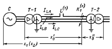
In Fig. 38-37 shows the power supply diagram of a step-down substation with transformer T-2 through a single line L from powerful system C. When the line operates on two phases for correct settings relay protection of the line, it is necessary to know the currents in the line under open-phase load mode and a combination of open-phase mode with various types of short circuit. at points K1 and K2.
Rice. 38-37. Network diagram with one-way power supply.
1. Load mode when phase A of the line breaks (Fig. 38-38)
In the design diagram (Fig. 38-38, a) and the complex equivalent circuit (Fig. 38-38, b), the following designations are used:
- phase e. d.s. power source (system);
- total positive sequence inductive reactance for the part of the circuit to the left of the break point;
- total positive sequence resistance for part of the circuit from the point of rupture to the secondary voltage buses of transformer T-2;
- the same in reverse sequence;
- the same zero sequence;
- positive sequence resistance of the load;
- the same in reverse sequence.
In table 38-5 shows the relationships between the components of currents in the line when operating on two and three phases.
Rice. 38-38. Phase A break on the line. a - design diagram; b - complex substitution scheme.
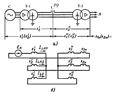
Table 38-5 Current ratios when a line phase is broken
Current ratio |
Calculation expression for current ratio |
|
|
|
|
In table 38-5 are marked:
I - current in phase under load operating mode on three phases;
-
the same when working on two phases;
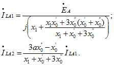
- positive sequence current of phase A under load mode and operation on two phases;
- the same in reverse sequence;
- the same zero sequence;
- total resistance of the positive sequence circuit in load mode relative to the break point;
- the same in reverse sequence;
- the same zero sequence.
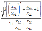
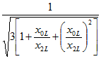
In accordance with the diagram in Fig. 38-38, b resistance and are equal:
2. Short circuit at the receiving end of the line (point K1) when the line operates on two phases (Fig. 38-39)
In Fig. 38-39 and in table. 38-6 are marked:
- total resistance of the positive (negative) sequence circuit to the short circuit;
- the zero-sequence resistance of the part of the circuit to the left of the short circuit;
- the same to the right of the short circuit.
Determination of currents in the line during a short circuit. at points K1 and K2 is fulfilled under the following assumptions:
1) load currents are not taken into account.
2) direct and negative sequence resistance to the short circuit point. equal.
In table 38-6 gives expressions for currents in phases and zero-sequence current at the supply end of the line at various types k.z. at point K1.
In table 38-6 does not provide data on single-phase short circuits. in phases B and C and two-phase short circuit. between phases B and C, since with a short circuit. not in the disconnected phase, the currents in the line will be the same as with the same type of short circuit. and work on three phases of the line.
Table 38-6 Currents in the line with a break in phase A and a short circuit at the receiving end of the line
Type of short circuit |
Currents in line phases |
||
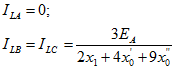
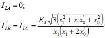
Single-phase phase A |
|
|
|
Two-phase between phases A and B |
|
|
|
Two-phase between phases A and C |
|
||
Two-phase to ground phases A and B |
|
|
|
Note. At two-phase circuit to the ground of phases A and C follows in the expression for replace a with , where |
|||

Rice. 38-39. Short circuit at the receiving end of the line when the line operates on two phases.
3. Short circuit on the secondary side of transformer T-2 (point K2) when the line operates on two phases (Fig. 38-40)
In table 38-7 gives expressions for currents in the phases of the line and the zero-sequence current of the line during a short circuit. at point K2. The given relations are valid under the assumptions specified above (see the short circuit at point K1).
Cases of a ground fault at point K2 are not considered, since these faults do not create a short-circuit mode.
Table 38-7 Line currents with a break in phase A and a short circuit on the secondary side of transformer T-2
Type of short circuit |
Currents in line phases |
Zero sequence current in the line |
|
|
|||
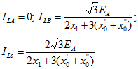
Between phases B and C |
|||
Between phases A and B |
|||
Between phases A and C |
|||
 (1 ratings, on average: 5,00 out of 5)

