Two-phase short circuit current formula. Vector diagrams of currents and voltages during a short circuit in the network. Dynamic resistance of devices
Three-phase short circuit current from the supply network is determined in kiloamperes according to the formula:
where U N NN is the average rated phase-to-phase voltage, taken as the base voltage; for 0.4 kV networks, the base voltage is taken to be 400 V;
The total total resistance of the circuit up to the point of a three-phase short circuit, which is the positive sequence resistance and is determined by the formula in millioms:
It's too difficult to tell you what to do without knowing more about the power system on both the primary and secondary sides of the transformer. Find a good reference to this using units of measurement. Current short circuit the following circuit breaking and bus fixing device must be at a minimum. For a two-way substation where transformers can run in parallel, double it. The assumed primary side current for this calculation is assumed to be infinite. For circuit breakers Use the breaker manufacturer's wattage rating for cascading in series.
where R 1∑ - total active resistance circuits up to the short circuit point, mOhm;
X 1∑ - total inductive reactance up to the short-circuit point, mOhm.
The total active resistance includes the resistance of the following elements:
The total inductive reactance contains the resistances of the following elements:
Two-phase current K3 is determined in kilometers using the following formula:
Switches do not have more than one manufacturer simple solution. Output feeders or high voltage feeders must be sized to require the rated power of the output feeder switches or fuses protecting it and the permissible voltage drop across the loads, whichever is larger.
Failure to comply with these requirements can lead to disaster if there is a short circuit on the load side of the breaker. An entire facility can be lost in such an accident, and anyone near the explosive switch is subject to serious injury or death. However, in my experience, this is a surprisingly common mistake.
![]() ,
,
where is the nominal average between phase voltage, taken as basic, B;
and are the total total resistances of the direct and negative sequences, and and is equal to mOhm.
Expression (19) can be written as follows
![]() =,
=,
Note, have much lower impedances than 75%. Transformers with solid or cast core and transformers with air cooled may be significantly lower, around 2%. The fault current on the supply side of your transformer is determined by your power source. Now you need to calculate the fault current at secondary transformer. Please note that this three-phase current fault current represents the maximum theoretical fault current. If you consider the fault impedance on the supply side of your transformer and add it to the transformer impedance, the actual maximum fault current available will be less than 3.
where is the total resistance of the circuit to point K3 with a two-phase short circuit, mOhm.
![]() ,
,
The single-phase short circuit current is determined by the formula:
Total active and inductive zero-sequence resistance to location K3, respectively, mOhm.
The current that is likely to flow in a circuit if the cables are short-circuited and the neutral cable is short-circuited is called the prospective short-circuit current. This is the highest current that can flow in the system. and security devices must be able to safely break it. The breaking capacity of a fuse or circuit breaker is one of the factors that must be considered when selecting it.
The effective breaking capacity of overcurrent devices is highly dependent on their design. In practice this can be difficult because to some extent it depends on impedance, which not only extends beyond the power system setting but also in real time. If the supply system impedance can be found, a simple calculation using the formula (Figure 21) can be used, but this is rarely the case. An alternative is to ask your local Electric Company.
36. Thermal resistance of devices.
Thermal resistance electrical apparatus is called the ability to withstand them without damage preventing further work, the thermal effect of currents flowing through live parts of a given duration. A quantitative characteristic of thermal resistance is the thermal resistance current flowing over a certain period of time. The most intense is the short circuit mode, during which currents can increase tens of times compared to the rated ones, and the power of heat sources can increase hundreds of times.
The problem is that they will likely defend themselves by citing a figure that is usually at least 16 kA over the true value. Rice. 21 Estimated short circuit current. The table is not applicable in London, where the density of the distribution system means that higher values may apply.
By then the fuses and circuit breakers will already be installed. The first method is to measure the supply's impedance by determining its voltage regulation, that is, the amount by which the voltage drops as current increases. If, when the 40 A current is flowing, the voltage drops to 238 V, the voltage drop will be due to the supply impedance. Fault current is an unintentional, uncontrolled, large current through an electrical system. Fault currents are caused by shorted contacts with very low impedance.
37.Dynamic resistance of devices
Electrodynamic resistance device is called its ability to withstand electrodynamic forces(EDF), which arose during the passage of short-circuit currents. This quantity can be expressed either directly amplitude value current i ding, in which the mechanical stresses in the parts of the device do not exceed the permissible values, or the multiple of this current relative to the amplitude rated current. Sometimes the electrodynamic resistance is assessed effective values current for one period (T = 0.02 s, f = 50 Hz) after the onset of the short circuit.
These can be shorts to ground or through phases. Resulting stream with high current can lead to overheating of equipment and conductors, excess forces, and sometimes even serious arcs, explosions, and explosions. Causes of errors include things such as lightning strikes, animals, dirt and debris, dropped tools, corrosion and human error.
Procedure for calculating short circuit currents
Calculations with errors are based on Ohm's law, in which the current equal to voltage, divided by resistance. When there is a short circuit, the resistance becomes very small, which means the current becomes very large. If the resistance was zero, then the calculated fault current will reach infinity. However, even copper wire has some resistance; it is not a perfect guide. Determining fault current involves understanding the impedance of the power supply at the fault location.
38. Procedure for calculating short circuit currents.
A short circuit (SC) is the connection of live parts different phases or potentials between each other or with the housing of equipment connected to the ground, in power supply networks or in power receivers. A short circuit can occur for various reasons, for example, deterioration of insulation resistance: in a humid or chemically active environment; in case of unacceptable heating or cooling of the insulation; mechanical failure of insulation. A short circuit can also occur as a result of erroneous actions by personnel during operation, maintenance or repair, etc.
Calculations with errors required
Knowing the available fault current is important when selecting protective devices, but it is also required by code. National Electrical Code 24 says. Service equipment in premises other than residential premises must be legibly marked in a field with a maximum permissible current damage. The field marking must include the date when the fault current calculation was performed and be durable enough to withstand the environment.
This means that on electrical equipment Field stickers must be installed, such as commissioning equipment that gives the available short-circuit current. This makes it easy to compare the short circuit current in the equipment with the maximum permissible fault current.
During a short circuit, the current path is “shortened” as it travels through the circuit bypassing the load resistance. Therefore, the current increases to unacceptable levels unless the power to the circuit is turned off by the protection device. The voltage may not turn off even with a protection device if the short circuit occurs at a remote point and therefore the resistance electrical circuit will be too high, and the current value for this reason will be insufficient to trigger the protection device. But a current of this magnitude may be sufficient to cause a dangerous situation, such as a wire fire. Short circuit current also produces an electrodynamic effect on electrical devices - conductors and their parts can be deformed under the influence mechanical forces, arising at high currents.
Any time there is a change in equipment, the fault current calculation must be redone. When changes occur in the electrical installation that affect the maximum available short-circuit current for service, the maximum available short-circuit current should be checked or recalculated as necessary to ensure that the ratings are sufficient. service equipment for the maximum possible fault current at the line terminals of the equipment. The required field markings in 24 must be adjusted to take into account the new maximum possible fault current level.
Based on the above, protection devices should be selected according to the conditions of the short-circuit current value (electrodynamic strength, indicated in kA) at the location of their installation. In this regard, when selecting a protection device, it becomes necessary to calculate the short circuit current (SCC) of the electrical circuit. The short circuit current for a single-phase circuit can be calculated using the formula:
IN electrical system there are several types possible malfunctions. A short circuit that causes current to bypass the normal load. A "ground fault" in which current flows into the ground. In three-phase systems there may be a short distance between one or more phases. This type of fault typically produces the highest fault currents. . The fourth fault type, open circuit fault, does not produce a short circuit current. An open fault occurs due to unintentional interruption of current.
Protective systems must prevent damage to equipment and protect people in all of the above situations. This means that leakage current calculations must be carried out in such a way that appropriate protective devices can be selected. Electrical fault could be either a bolt or arc fault.
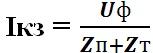
where Is is the short-circuit current, Uph is the phase voltage of the network, Zp is the resistance of the circuit (loop) phase-zero, Zt is the total resistance of the phase winding of the transformer on the low-voltage side.
where Rп is the active resistance of one wire of the short circuit circuit.
A bolted joint provides a strong connection. This allows the protector to flow through the conductor. This type of failure can occur when the installer connects the power supply to ground rather than to the point where it should be connected. When the power is turned on, there will be an immediate bolt error that turns off protective device. Because the flow is contained, damage is usually limited. However, bolt fault produces the highest fault currents.
An arc fault occurs when there is no solid connection, but the conductors get close enough that current jumps across the gap, creating an arc. The initial arc ionizes the air, creating a plasma that allows the current to be rapidly increased and maintained, resulting in an arc flash or arc jet.
where ro - resistivity conductor, L is the length of the conductor, S is the cross-sectional area of the conductor.
Xn is the inductive reactance of one wire of a short circuit circuit (usually taken at the rate of 0.6 Ohm/km).
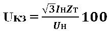
Transformer short circuit voltage (% of Un):
The fault in a three-phase system can be symmetrical or asymmetrical. In a symmetrical fault, all three phases are equally affected. Most three-phase faults are asymmetrical, making fault current calculations difficult. Before performing the current fault calculation, all possible current sources must be identified. This may include some current sources that may not have been considered. There are four possible sources of short circuit current.
When the power fails, as happens with a short circuit, the inertia of the mechanical load on the motor will continue to spin the motor. The motor will then act as a generator feed current and this will contribute to the overall fault current flow. Induction Motors: This type of motor will also become a generator if there is a short circuit fault in the system. However, the damage current generated asynchronous motor, will only last a few cycles. Electrical utility system: most of The fault current usually comes from the electrical utility. The level of short circuit current will depend on: the secondary voltage of the transformer and the impedance impedance of the impedance generators of the circuit from the transformer to the short. The current will be approximately equal to the starting current of the locked rotor of the motor. . To simplify the calculation of the fault current, it is assumed that all electric generators in the system are in phase and that they operate at the rated system voltage.
Hence the total resistance of the phase winding of the transformer (Ohm):
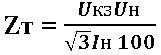
where Us - short-circuit voltage of the transformer (in % of Un) is given in reference books; Un - Rated voltage transformer, In - rated current of the transformer - are also taken from reference books.
Bolted three-phase condition
The short circuit investigation is carried out so that the fault current can be calculated. This usually refers to the worst case scenario, which is a three-phase fault condition with bolted connection. Based on this situation, another fault condition can be approximated.
What is important is the contribution of fault current from the motors in the system. In many cases, engines can contribute four to six times normal current full load. Even if the current is of very short duration, it is very important that it is included in the fault current calculation.
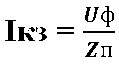
The above calculations are performed at the design stage. In practice, it is difficult to do this at existing facilities due to the lack of initial data. Therefore, when calculating the short-circuit current, in most cases it is possible to take the resistance of the phase winding of the transformer Zt equal to 0 (real value ≈ 1∙10-2 Ohm), then:
The given formulas are suitable for ideal conditions. Unfortunately, they do not take into account such factors as twists, etc., which increase the active component of the Rп chain. Therefore, an accurate picture can only be given by direct measurement of the resistance of the phase-zero loop.
39.Release current, current setting, circuit breaker cut-off current.
Release
The current flowing through the electromagnetic release of the circuit breaker causes the circuit breaker to turn off when it quickly and significantly exceeds the rated current of the circuit breaker, which usually occurs when there is a short circuit in the protected wiring. A short circuit corresponds to a very quickly increasing high current, which the device takes into account electromagnetic release, which allows you to almost instantly influence the tripping mechanism of the circuit breaker with a rapid increase in the current flowing through the release solenoid coil. The response speed of the electromagnetic release is less than 0.05 seconds.
Setpoint current on the scale is marked by the factory; In the table everywhere, except where otherwise specified, it is indicated as a percentage of the rated current of the release. Between the lower and upper limits indicated on the scale, the settings are adjusted smoothly.
Cut-off e that is the minimum current value that causes instantaneous operation of the machine).
For single-phase short circuits, the symmetry of currents and voltages three-phase system is violated. Based on the symmetrical components method, the asymmetrical single-phase short circuit is replaced by three three-phase conditionally symmetrical short circuits for symmetrical components of different sequences. The single-phase short circuit current consists of three components - direct (I 1), reverse (I 2) and zero (I 0) sequences. The resistances of the elements also consist of direct (R 1, X 1, Z 1), reverse (R 2, X 2, Z 2) and zero sequence resistances (R 0, X 0, Z 0). Except electric machines The positive and negative sequence resistances for the elements are equal to each other (R 1 = R 2, X 1 = X 2) and are equal to their values for a three-phase short circuit. Zero sequence resistances are usually much greater than positive and negative sequence resistances. In practical calculations, the following is accepted for three-core cables: ; for busbars: ![]() [L.7]; for overhead lines: ; [L.4].
[L.7]; for overhead lines: ; [L.4].
For power transformers having a winding connection circuit D ¤ Y n, the zero-sequence resistance is equal to the positive-sequence resistance. For transformers with a winding connection circuit Y ¤ Y n, the zero-sequence resistance significantly exceeds the positive-sequence resistance.
The single-phase short circuit current will be determined:
Here: – the average rated voltage of the network in which the short circuit occurred (400 V); – total resulting zero-sequence resistance relative to the short-circuit point, mOhm.
The resulting resistance of the short-circuit circuit is determined, mOhm:
Here: – equivalent inductive reactance of the external system to the supply transformer 6-10 / 0.4 kV, reduced to the LV stage, mOhm;
– positive sequence resistance of the step-down transformer, mOhm;
– reactor resistance, mOhm;
– busbar resistance, mOhm;
– resistance cable lines, mOhm;
– overhead line resistance, mOhm;
– resistance of current coils of automatic circuit breakers, mOhm;
– resistance of current transformers, mOhm;
– transition resistance of fixed contact connections and moving contacts, transition resistance of the arc at the short circuit point, mOhm;
– zero-sequence resistance of the step-down transformer, mOhm;
– zero-sequence resistance of busbars, mOhm;
– active and inductive zero sequence resistance of the cable, mOhm;
– zero sequence resistance overhead line, mOhm.
For a given power supply system (Fig. 4), it is necessary to determine the periodic current values for given points with a three-phase and single-phase short circuit (by the method of symmetrical components).

Fig.4. Design diagram and equivalent circuit
1. Using the design diagram, we draw up an equivalent circuit (Fig. 4).
2. Find the resistance of the short circuit circuit elements in named units (mOhm).
2.1. The inductive reactance of the external system to the supply transformer is 10 / 0.4 kV (high voltage circuit) (if the short-circuit power on the high side of the transformer is unknown, then it can be accepted).
![]() ; mOhm
; mOhm
2.2. Active and inductive resistance of the supply transformer (positive and negative sequence resistance: ![]() , ; resistance zero after-
, ; resistance zero after-
sequence: , ) [L. 7]:
2.3. Busbar resistance is 0.4 kV.
For flat copper busbars with dimensions 80 x 10 mm (with a geometric mean distance between phases of 15 cm), specific active and inductive resistances at alternating current for direct and reverse sequences are equal, [L.6]. For the zero sequence [L.7]:
Active and inductive resistance of three busbars 0.4 kV direct, negative and zero sequence:
Total resistance of all three busbars:
2.4. Active and inductive resistance of cables.
Specific active and inductive resistances of individual cables of direct, negative and zero sequences ( guidelines):
Values of active and inductive resistance of cables:
2.5. Active and inductive resistance of automatic circuit breakers (including resistance of current coils of releases and transition resistance of contacts) [L.7].
Total resistance of all machines:
3. Single-phase short circuit current for point “K 1”.
The resulting active and inductive resistance of the short circuit circuit for a single-phase short circuit at point “K 1”:
Single-phase short circuit current at point “K 1”:
4. Three-phase short circuit current for point “K 1”.
The resulting active and inductive resistance of the short circuit circuit during a three-phase short circuit at point “K 1”:
Three-phase short circuit current at point “K 1”:
4. Guidelines for calculating short-circuit currents and selecting electrical equipment. / Ed. B.N. Neklepaeva. – M.: Publishing house. NC ENAS, 2001. – 152 p.
5. Kulikov Yu.A. Transients in electrical systems./Yu.A.Kulikov. – Novosibirsk: NSTU Publishing House, 2002.–283 p.
6. Handbook for the design of power supply, power lines and networks. / Ed. Ya.M. Bolshama, V.I. Krupovich, M.L. Samovera. Ed. 2nd, Revised and additional – M.: Energy, 1974. – 696 p.
7. Handbook for power supply design. / Ed. SOUTH. Barybina and others - M.: Energoatomizdat, 1990. - 576 p.
8. Electricity supply guide industrial enterprises. / Under general ed. A.A. Fedorov and G.V. Serbinovsky. In 2 books. Book 1. Design and calculation information. – M.: Energy, 1973. – 520 p.
9. Rules for electrical installations. – 6th ed. – St. Petersburg: Dean, 1999. – 924 p.
APPENDIX A
 (1 ratings, on average: 5,00 out of 5)