What devices are used against short circuit currents. What electrical devices are used to protect electrical networks from short circuit currents and overloads?
During operation, any electrical installation it may arise short circuits, unacceptable overloads or maybe sharply tension will decrease. The consequences of these modes can be serious damage to electric locomotive equipment; To prevent them, various protections are used.
We have already become acquainted with two devices for protection against short circuits and overloads - this is a high-speed switch on electric locomotives direct current and main switch on electric locomotives alternating current.
The high-speed and main switches cannot protect the power circuit under all abnormal conditions. Therefore, to control the actions electrical devices, the operation of an alarm system indicating a violation of the normal mode of their operation, automatic shutdown circuits or the entire installation, special protections apply. Their main apparatus is relay.
According to the principle of operation, relays can be electromagnetic, thermal, electrodynamic, etc. Due to the simplicity of the device, the possibility of using both direct and alternating current is most widespread in electrical systems, including on electric locomotives, received electromagnetic relays.
Automatic switches with the thermal relay. Overload protection and short circuit Overload protection. never higher than rule 2 is used for overload protection. able to perform this function: Rule 1 satisfies the general conditions for overload protection. when the current exceeds the set value.
This protection must be provided by devices that can cause the circuit to open at the appropriate time. These considerations should be analyzed by the designer depending on the type of circuit being installed. although the operation of the switch will be guaranteed even in case of abnormal loads that can be supported. It is clear that when choosing the maximum protection condition, the situation can affect the continuity of service. On the other hand, choosing a switch with a calibrated current equal to bandwidth cable.
Rice. 96 Electromagnetic relay connection diagram
The operating principle of such a relay, which protects, for example, Electrical engine M (Fig. 96) from overload, is as follows. If the current in the motor increases above the maximum permissible, the relay armature, through the coil of which the current of the protected circuit passes, is attracted to the core, overcoming the spring force. In this case, contacts a and b, closing, turn on signal lamp; When it lights up, it signals to the driver that the traction motors are overloaded. Contacts c and d cause the main or high-speed switch to trip, breaking the circuit holding coils.
The current at which the relay operates is called setting current. It is adjusted by changing the spring tension. An electromagnetic relay, with the appropriate setting, can be used as a maximum voltage relay or as a low current or voltage relay. In the first case, when the voltage increases above the permissible value, the armature is attracted and the relay contacts, for example, close; in the second case, the armature disappears and the contacts, on the contrary, open.
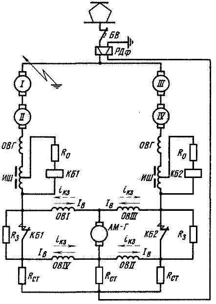
On electric locomotives VL11, VL10, VL8, the overload relay contacts are not included in the circuit of the holding coil of the high-speed switch. When closed, they turn on a warning lamp, the lighting of which indicates an overload of any traction motor circuit. If an overload occurs in the weakened excitation mode, then the excitation weakening contactors are switched off under the action of the relay. The number of overload relays corresponds to the number of parallel-connected motor circuits. If a short circuit on DC electric locomotives occurs in the circuit behind the traction motors connected in series, then the high-speed switch may not work, since the e.g. d.s. of serviceable motors connected at the beginning of the circuit will increase due to an increase in current. The short circuit current will be small. Taking this into account, electric locomotives VL11, VL10, VL8, VL23 use sensitive differential protection, made on a special relay.
Let's consider the principle of operation of this relay. Through the window of the magnetic circuit of the differential relay RDf, the cables of the beginning and end of the protected section of the power circuit of the motors pass, the current of which is directed in the opposite direction (Fig. 97).
In general, there are the following practical cases of obligation. whose current was required to the line with the rotor locked. Provided that their duration does not allow reaching unacceptable temperatures in the circuit insulation. Thermal relay. these overloads. Cases in which overload protection is not recommended. which allows the passage of low intensities for a certain time and instead. These devices are called timing or inverse thermal performance. In fire pumps.
Example: in the magnetic circuits of a transport crane. thus avoiding excessive shutdowns that could impair the normal operation of the engines. Typically, the device measures heat indirectly by monitoring the current flowing through the circuit. This means that the overload protection device is intelligent. The standard recommends eliminating conductor overload protection when opening a circuit would create a risk.

Rice. 97. Differential protection scheme for DC electric locomotives
At one end of the magnetic circuit there is a switching coil, powered by a 50 V power source. Under the influence of its magnetic flux, the armature is attracted, as a result of which the contacts connected to the holding coil circuit of the high-speed switch are closed. During normal operation, the magnetic fluxes generated around the input and output cables cancel each other out. In Fig. 97 the conventional cross-section of the cables passing through the magnetic circuit window is shown in circles; in the remaining sections of the circuit, the cables are depicted as electrical connecting lines. The direction of current in cables from the drawing plane to us, as is customary in electrical engineering, is shown by a dot, and from us to the drawing plane by a cross.
In the event of a short circuit to ground, for example at point K, the current passing through the input cable, and therefore the magnetic flux created by it, will increase sharply. In the output cable, on the contrary, the current and magnetic flux will decrease to zero. The magnetic flux of the input cable is directed counter to the flux of the switching coil.
As a result, the relay armature, under the action of the spring, will come off the magnetic circuit and break the circuit of the holding coil BV.
The short circuit current is not immediately interrupted by the high-speed switch and continues to increase for some time after the differential relay is activated. Therefore, the magnetic flux generated by the input cable current can again attract the relay armature. To prevent this, a relay is installed in the middle part of the magnetic circuit magnetic shunt. The air gaps of this shunt are smaller than the gap between the disconnected armature and the end of the magnetic circuit. Therefore, after the relay is turned off, the magnetic flux created by the input cable current will be closed through the magnetic shunt.
A differential relay cannot protect traction motors from overload, since there will be no inequality, or, as they say, current imbalance, in the cables. Current imbalance is possible only with a short circuit to ground.
On AC electric locomotives, differential protection of traction motors is not needed, since they are always connected in parallel and an overload relay is included in their circuit. It is used to protect against short circuits in rectifier installations. In this case, the coil differential relay unit (RDB) together with the choke, they are connected between two points in the circuit of the secondary windings of the traction transformer, which have equal potentials. Without dwelling in detail on the action of the protection, we note that it responds to the rate of increase of the short circuit current in the rectifier installation. With a rapid increase in current, the inductor in the circuit where it is installed will delay the increase in current. Therefore, the bulk of the current will flow through the circuit of relay coils. Therefore, the magnetic flux of the holding coil will be significantly different from the magnetic flux caused by the short circuit current. The relay will operate and its contacts will break the circuit of the main switch holding coil.
On AC electric locomotives, it is necessary to protect power circuits from short circuits to the ground, or more precisely, to the body (body) of the electric locomotive. This is because the transformer secondary winding, rectifiers and traction motors are not connected to ground, as in a DC locomotive where a ground fault causes the high-speed switch or differential protection to operate. An insulation failure at one point of the power circuit will not cause damage, but a short circuit at two points already creates an emergency mode. Therefore, it is necessary to monitor the insulation condition of the power circuit.
This is done using grounding relay- the so-called earth protection. The winding of the relay РЗ (Fig. 98) is connected to the locomotive body and is included in the rectified voltage circuit selenium rectifier SV.
For correct use installations and machines, it is good that safety devices are allowed in a certain way and for a certain time. it doesn't happen instantly. Indirect: If the current passes through a heating coil that surrounds the workpiece. Direct: If the entire circuit current passes through the workpiece. This. this heating can be: a sheet consisting of two metals with different coefficients of expansion and a heated current flowing through the main circuit.
When the curvature reaches a certain point. in these cases. To avoid these inconveniences. you can turn off the circuit by opening thermal relay. at the required speed to ensure that insulating materials reach temperatures that damage them. Short circuit General terms protection. Because alamines are joined mechanically or by welding. within normal values. triggers some mechanism. the workpiece will no longer dissipate as much thermal energy and the expansion process will begin.

Rice. 98. Power circuit protection circuit against ground faults
The rectifier is powered by secondary winding voltage 380 V traction transformer. To be able to use the same relay for two groups of traction motors, it is connected through two identical resistors R to points of the power circuit that have equal potentials. In the event of a short circuit, for example, a rectified current circuit is formed at point a, the relay is activated and turns off the main switch.
Auxiliary machine circuits are protected with overload relay, which cause tripping of the main or high-speed switch, as well as fuses and differential protection. Asynchronous motors auxiliary machines of AC electric locomotives have thermal protection RT from overload. The thermal relay (Fig. 99) uses bimetallic plates on which disconnecting block contacts are installed.
IN three-phase circuits with neutral. The value of this current is an estimate. measured between phase and neutral. Prospective short circuit current. the greater the current. Phase - phase. the greater the distance, the less current. - Line length to failure point. Neutral - Three Phase Balanced This last condition is the most serious. Short circuit current characteristics The calculated short circuit current at the installation point is the current that will be present if there is negligible resistance between the voltage conductors.
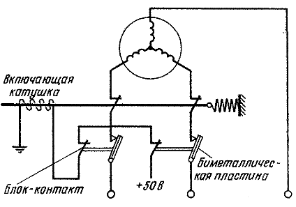
Fig.99. Thermal protection circuit
The metals from which the plates are made have different linear expansion coefficients. In the event of prolonged overload or short circuit, the elements heat up and bend. After the deflection of the plates reaches a certain value, the block contacts will break the circuit of the switching coil and the contactor will turn off. When normal temperature is established, the elements will take their original position. Thermal protection relay included in every two wires supplied to the engine.
Features of violations of electric braking modes depend on the braking system - rheostatic or regenerative, the connection diagram and the engine excitation system.
In the rheostatic braking mode with sequential excitation of motors, overload can occur, as in traction mode, in the event of excessively rapid switching off of the rheostat stages. To prevent such overload, the same relays are usually used as in traction mode.
When protecting against short circuit currents in rheostatic braking mode, as in traction mode, differential relays and grounding relays can be used.
Protection against short circuits in regenerative braking mode on electric locomotives VL8, VL10 and VL11 is provided fast acting electromagnetic contactors Design bureaus with arc-extinguishing chambers. When they are turned off, the direction of the current in the excitation windings of the traction motors changes and intensive damping of the magnetic flux occurs. The method of switching on high-speed contactors in a cyclic stabilization circuit with an exciter with counter-excitation created by the OVG windings in the armature circuit of traction motors is explained in Fig. 100.
Not suitable for short circuit protection purposes. Although breaker interruption tests are based on a symmetrical component. Short Circuit Protection Calculation of Short Circuit Current To calculate the calculated short circuit current values at any point in the installation, you only need to apply the following formula and find out the calculated impedance values from the beginning of the installation to the point being analyzed. Table for estimating short circuit current.
Thermomagnetic switch. Short circuit protection. cool and destructive. The intensity is quite acceptable if there is a connection error or insulation failure. Features: Fuses and correct calibration. The two pins of the socket are in contact. Short circuits occur when all or part of their impedance disappears in a circuit. Switches with magnetic relay. The latest generation limit switches can have pre-arc times of less than 1 ms and high arc voltages, obtaining limiting factors less than.
Rice. 100. Traction motor protection circuit
from short circuit currents in regenerative mode
The tripping coils of high-speed contactors KB1 and KB2 are connected in parallel to the coils through limiting resistors Ro inductive shunts ISH. An increase in the short circuit current in the traction motor circuit causes a sharp increase in the voltage on the inductive shunts. A current exceeding the contactor setting current passes through the trip coil, causing its power contacts to open. Contactors do not completely open the circuit, but introduce resistors R3 into it, the resistance of which is chosen such that dangerous overvoltages do not occur. After opening the contacts of the KB contactors most of The current of the traction motors passes through their excitation windings counter to the excitation current, causing rapid demagnetization of the motors.
To protect against short circuits, AC electric locomotives with regenerative braking are equipped with high speed switches in a rectified current circuit. On electric locomotives VL80r, individual high-speed switches are introduced into the circuit of each engine.
Inverter protection devices. Surge protection. Reverse polarity protection Overcurrent protection. Devices for protecting photovoltaic generator circuits. Backlash protection. Devices for disconnecting a photovoltaic generator. The installation of external protection devices must always be assessed in relation to: the installation conditions of the photovoltaic generator, the inverter's own characteristics, the devices built into the inverter and their characteristics.
Plant protection: overload
Overload: An enormous transient voltage occurring at one or more points in a system that may exceed the system's insulation voltage. Causes: Can be caused by the activation and introduction of highly inductive or capacitive loads or atmospheric phenomena. External overloads: caused by lightning, for example when it occurs near high, medium and low voltage lines. Internal overvoltages: caused by opening and closing devices installed in power circuits or system failures.
Plant protection: surge wiring
Minimize the area over which the cord wires that make up the wiring overlap.Fuse - this is the simplest device that protects the electrical network from short circuits and significant overloads. The fuse consists of two main parts: a porcelain base with metal thread and adjacent fuse-link (Fig. 42, a) The fuse-link is designed for rated currents of 10, 16, 20 A.
Instead of fuses, circuit breakers (circuit breakers) can be used. The machines are turned on manually, and can be turned off manually or automatically, as a result of the operation of releases built into the housing.
Plant protection: surge protection
Route the wiring so that it has two rings in which the induced current flows in the opposite direction. All string inverters integrate surge suppressors as thermally controlled and replaceable varistors. Are protective devices inside the inverter sufficient to protect the inverter?
Plant protection: overcurrent protection
Because of the way they are wired inside the inverter, surge suppressors protect against differential mode surges and common mode surges. Given the nature of the generator, when can we talk about overload in the inverter? When the irradiated photovoltaic generator is connected to the inverter and the internal capacitors are completely discharged.
Circuit breakers with thermal releases are designed to protect against overloads. As thermal release serves as a bimetallic strip. When an overload current passes through it, it bends and activates a tripping mechanism that turns off the machine.
An electromagnetic release consists of a coil, a core and a spring. Circuit breakers with electromagnetic releases are used to protect against short circuits. The short circuit current, passing through the coil, helps to draw the core into it, which compresses the spring and activates the tripping device. The machines may have a thermal or electromagnetic release, or both at the same time, i.e. combined. In lighting networks instead of fuses Threaded circuit breakers of type Par 6, -A can be used; 10A and 16A; 250 V (Fig. 42,b) and AE10 circuit breakers for 16A; 25A; 250V (Fig. 42, c).
Is there a limit to the reverse maximum current supported by the modules?
Under such conditions, when the photovoltaic assemblies are connected to the inverter, the capacitors behave like a short circuit and therefore the photovoltaic generator supplies a current equal to its maximum current. Module manufacturers report information sheet indication of the maximum fuse rating, which is intended as maximum size fuse, which is inserted in series into the module to create reverse current protection.
When is it necessary to insert reverse current overload protection? When reverse current is present in the circuit above the maximum fuse rating; Typically, when there are more than three lines in parallel with each other. What are the possible overcurrent protection capabilities? Blocking Diode: Inserting a blocking diode in series with each circuit prevents reverse currents from flowing through the circuit. Circuit breakers. Inserting a fuse in series on each circuit will prevent back currents from flowing through the rope.
Rice. 42. Protection devices against short circuit currents and overloads: A - fuse; b - threaded automatic switch Steam; c - automatic switch AE10; g - automatic switch AP50B; 1 - arc extinguishing chamber; 2 - electromagnetic release; 3 main contacts; 4 and 5 - manual on and off buttons; 6 - plastic base
Disconnector: A device capable of isolating between two parts of a circuit. A specific characteristic of a disconnector is its ability to provide insulation between two sectional parts of a circuit. Switch: A device capable of causing the opening of a charging circuit, that is, a circuit through which current flows.
The disconnector must be able to cut the circuit and the internal fault of the inverter. Therefore, the inverter “maintains” the line voltage and cannot change it directly. To connect to the grid, it is enough that the inverter has AC voltage with voltage and frequency within the range allowed by the converter itself.
To protect three-phase electrical networks three-phase circuit breakers of the AE20, AP50B, etc. series are used. The preferred application is circuit breakers series AP50B (Fig. 42, d), since the contacts for connecting wires or cables are covered with a lid, which increases electrical safety during their maintenance. Automatic switches AP50B are produced with rated currents of 6, 3; 10; 16; 25 and 40 A.
Circuit breakers, in their primary function of overcurrent protection, operate through triggers, which can be thermal, magnetic or electronic. The most traditional circuit breakers for general use equipped with thermal triggers for moderate overcurrents and magnetic triggers for high overloads. Hence the term thermomagnetic switches.
The thermooctopus trigger consists of a bimetallic blade that bends under the influence of heat created by the passage of current. This temporary deformation of the blade, caused by the different expansions of its two constituent metals, eventually causes the circuit breaker to open. The bimetallic thermal trigger has a reverse time triggering characteristic, that is, triggering occurs in a shorter time and the higher the current.
For normal operation protective devices, it is necessary to determine the operating current, which is used to select the fuse link and select the circuit breaker. To do this, it is necessary to determine the power of consumers that this device will protect. It is generally accepted that with a single-phase load, 1 kW of power produces a current of 5 A; for three-phase - 1 kW - 3 A load, determine the rated current of the fuse link or circuit breaker.
Some thermal triggers have an adjustable current range. There are also temperature compensated thermocouples. The magnetic trigger consists of a coil that attracts the hinged part when the current reaches a certain value. This displacement of the armature by mechanical clutches causes the main contacts of the circuit breaker to open. There are circuit breakers that have an adjustable magnetic shutdown.
Figure 1 shows a typical time characteristic of a thermal magnetic circuit breaker, showing the operation of thermal overload trip and magnetic trip. The electronic trigger finally includes current sensors, signal processing and control electronics and actuators. Current sensors consist of a magnetic circuit and produce an image of the current being measured. The electronics processes the information and, depending on the magnitude of the measured current, determines that the circuit breaker will trip at the expected time.
For example, it is necessary to select protection for electrical wiring in the house and for a three-phase electric motor with a power of 3 kW. We determine the total load in the house by addition, we get 2.2 kW (2200 W). 2, 2 5 = 11 A. The rated current of the fuse link or circuit breaker must be more current worker. We choose a 16 A fuse link or an AE circuit breaker with a rated current of 16 A.
The time characteristic of electronic triggers has three operating zones: - long-term thermal protection zone, which represents. Rice. 1 - A typical time characteristic of a thermomagnetic circuit breaker allows one to simulate the temperature rise characteristics of conductors; - short delay zone providing protection against remote fault currents. Short delay, compatible with conductor temperature rise limits, provides selectivity with high-pass protectors; - instant work zone, which is high short circuit protection and immediately after the circuit breaker.
For an electric motor: 3 3 == 9 A. Select the AP50B automatic machine for 10 A.
A more precise choice of start-up protection equipment is outlined below.
How to choose a fuse link?
The currents of fuse links for lighting network wires are selected according to rated current
Il.st>I nom
When choosing fuse links for protection asynchronous electric motors It must be taken into account that the starting current of the motor is 5-7 times higher than the rated current. Therefore, it is impossible to select a fuse-link based on the rated current, since it will burn out when starting the electric motor.
For asynchronous electric motors with a squirrel-cage rotor at a low switching frequency and easy starting conditions (tstart = 5-10 s), the rated current of the fuse link can be determined by the expression
Ipl.in>0.4 Istart,
where I is the starting current of the electric motor, A.
Under difficult operating conditions (frequent starts, take-off time up to 40 s)
Ipl.int >(0.5 - 0.6) Istart
How to choose a circuit breaker?
Automatic air circuit breakers are used to protect network sections from short circuits, overloads or voltage drops. They are also used for infrequent operational switching on and off of asynchronous squirrel-cage electric motors. The designs of circuit breakers differ in their releases - built-in devices in the form of protective relays for remote shutdown. There are overcurrent (electromagnetic or thermal), undervoltage (zero) and independent releases. Electromagnetic releases operate almost instantly (in 0.02 s), thermal releases disconnect the circuit depending on the duration and current strength exceeding the setting of the thermal release. If there is a combined release (that is, electromagnetic and thermal), the switch trips instantly in case of overcurrents and with a time delay from overloads determined by the thermal release. When the voltage drops to 70-30% of the rated voltage, the undervoltage release is triggered.
The conditions for selecting automatic air circuit breakers are as follows:
1) the rated voltage of the switch must correspond to the mains voltage, that is
Un.aut>Uc;
2) the rated current of the machine must be equal to or exceed the operating current: In.aut>Ip;
3) rated current of the circuit breaker release
must be equal to the operating current (for example, of an electric motor) or exceed it: In. rast> Ip;
4) correct operation electromagnetic release the machine is checked from the condition
Iwork.rast>1.25Imax
If a machine is used only with a thermal release, then according to the conditions reliable protection against short circuits, it is also necessary to install fuses in series with it.
What is a magnetic starter used for?
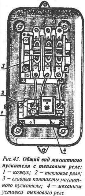
Magnetic starters (Fig. 43) are designed for remote control electric motors and other electrical installations. They provide zero protection, i.e. when the voltage disappears or when it decreases to 50 - 60% of the nominal value, the coil does not hold the magnetic system of the contactor and the power contacts open. When the voltage is restored, the pantograph remains disconnected. This eliminates the possibility of accidents associated with spontaneous starting of an electric motor or other electrical installation. Starters with thermal relays also protect electrical installations from long-term overloads.
The most widespread are magnetic starters of the PME, PML and PMA series.
These series are manufactured in open, protected, dust-proof and dust-splashproof. permeable design for voltages of 220 and 380 V. They can be reversible and non-reversible. Reversing starters, along with starting, stopping and protecting the electric motor, change the direction of its rotation.
Thermal relays TRN (two-pole) and TRL, RTI (three-pole) are built into magnetic starters. They are triggered under the influence of the motor overload current flowing through them and disconnect it from the network.
Marking magnetic starters deciphered as follows: the first number after the combination of letters indicating the type of starter indicates the value that corresponds to a certain current value (0 - 6.3 A; 1 - 10 A;
2 - 25 A; 3 - 40 A; 4 - 63 A; 5 - 80 A; 6 - 125 A);
the second - execution by the type of protection against environment(1 - open design; 2 - protected; 3 - dust-proof; 4 - dust-splash-proof), third - design (1 - non-reversible without thermal protection; 2 - non-reversible with thermal protection; 3 - reversible without thermal protection, 4 - reversible with thermal protection ).
What is a thermal relay used for and how to choose it?
Thermal relay (Fig. 43) is used to protect the electric motor from overloads.
The thermal relay and the rated current of the thermal element, if there are no special requirements for thermal protection, are selected in compliance with following conditions: the maximum continuous mode current of the relay must be no less than the rated current of the protected motor; the relay setting current must be equal to the rated current of the protected motor or slightly more (within 5%); The margin for adjusting the set current both in the direction of increasing and decreasing should be the greatest. To do this, one or two free divisions are left on the setting scale on both sides of the position of the regulator corresponding to the selected setting current.
Why and how is zeroing performed?
- annulment - the main measure of protection against damage electric shock in electrical installations with voltage up to 1000 V with dead-earthed neutral power supply if touched metal cases electrical equipment and metal structures that are energized due to damage to the insulation of the network or electrical installations.
Any short circuit of live parts to neutralized parts thus turns into a single-phase short circuit, which leads to disconnection of the emergency section of the network.
As zero protective conductors zero working conductors, specially provided conductors (the fourth or third core of a cable or network wire, steel strips, etc.), steel electrical wiring pipes, aluminum cable sheaths, metal building structures, metal busbar casings, all pipelines laid openly can be used , except for pipelines for combustible and explosive mixtures, sewerage, central heating and domestic plumbing. In terms of conductivity (resistance), all listed neutral wire grounding devices must satisfy PUE requirements. It is prohibited to install disconnecting devices in neutral conductor circuits, except in cases where all current-carrying wires in the installation are simultaneously disconnected.
To neutralize single-phase household electric stoves, a branch should be made from the neutral working conductor (bus) of the floor panel to the input
de, performed separate wire, whose cross-sectional area is the same as that of the phase. This wire must be connected to the neutral working conductor in front of the meter before the disconnecting device.
When three-phase electric stoves are closed, it is not allowed to use the neutral working conductor as a neutral working conductor.
For grounding luminaires, the inputs into which are made with a protected wire or unprotected wires in a pipe (metal hose) or when hidden wiring, make a branch from the zero working conductor inside the lamp. When introducing open, unprotected wires into the luminaire, you should use flexible wire(branch), connected on one side to the neutral working wire on a fixed support, and on the other to the grounding screw of the housing.
In outdoor installations and in explosive rooms, for grounding, you must use a free cable core or a free wire of an overhead network, connected to the zero working conductor in a junction box, and in B-1 rooms - in the nearest group shield.
In order to equalize the potential in all rooms and outdoor installations where zeroing is performed, all metal constructions piping, equipment housing, etc. must be connected to the neutral network.
How is grounding performed?
The grounding device consists of a ground electrode, grounding lines and grounding conductors. There are two types of ground electrodes: natural and artificial.
Natural grounding conductors include metal structures of buildings and structures that are securely connected to the ground.
As grounding conductors, steel pipes of electrical wiring, lead and aluminum cable sheaths, metal pipelines for all purposes, laid openly, are used. - it is prohibited to use pipelines for flammable and explosive mixtures, as well as those used for automatic watering of livestock, for this purpose.
Use of naked aluminum conductors for laying in the ground as grounding conductors and grounding conductors is prohibited.
All natural grounding agents for greater reliability, connect to the grounding lines of the electrical installation with at least two conductors connected to the ground electrode in different places. The connection is made close to the entrance to the building using welding or clamps (for pipes), the contact surface of which is tinned. The pipes in the places where the clamps are laid are cleaned. Places and methods of connecting conductors are chosen taking into account possible repair work pipelines. When disconnecting pipelines, it must be ensured continuous action grounding device.
If natural grounding electrodes and grounding conductors are absent or if they do not provide the required rated resistance, then artificial grounding electrodes are used.
The following are used as artificial grounding conductors: pipes, angle steel, metal rods, etc., horizontally laid steel strips, round steel, etc. In case of danger of increased corrosion, copper-plated or galvanized grounding conductors are used. -grounding conductors and grounding conductors laid in the ground must not be painted.
Installation of the external grounding loop begins with marking the route and digging trenches 0.6-0.8 m deep (below the soil freezing level).
Artificial ground electrodes in the form of segments steel pipes, round rods or angles 3-5 m long are driven into the ground so that the electrode head is at a depth of 0.5 m from the surface. -recessed electrodes are connected to each other with a steel strip using welding. The welding points are covered with heated bitumen to protect against corrosion. A grounding line made of steel tires is removed from the grounding conductors. Grounding conductors and grounding conductors laid in trenches are covered with earth that does not contain stones, construction waste, and compact tightly. The number of ground loop electrodes depends mainly on the resistivity of the soil, the length and location of the electrodes. To obtain a grounding resistance of up to 10 Ohms, it is necessary to drive from 2 to 30 electrodes.
The connection of grounding conductors to each other and connection to structures is carried out by welding, and connection to the housings of devices, machines, etc. - by bolted connections. If vibration is present, use locknuts, spring washers, or other anti-shock measures. weakening the connection. Welding seams are made with a length equal to twice the width of the conductor with a rectangular cross-section or six diameters with round section. Connectable contact surfaces bolted connections cleaned to a metallic shine and coated thin layer Vaseline.
Each grounded element of the electrical installation is connected to the grounding line with a separate conductor. Serial connection these conductors are prohibited.
Grounding conductors located in premises must be accessible for inspection. To protect against corrosion, bare steel wires are painted with black oil paint.
How to measure ground loop resistance?
To measure the resistance of the ground loop, a special device M416 is used.
For rough measurements of ground resistance, clamps 7 and 2 connect with a jumper and connect the device to the measured object using a three-clamp circuit (Fig. 44, a). At precise measurements remove the jumper from the terminals 1 And 2, connect the device to the measured object according to the four-terminal circuit. This circuit eliminates the error introduced by the resistance of connecting wires and contacts. Before measurement, adjust the device in the following sequence. Place it horizontally and move the measurement limit switch to the “5 Ohm Control” position. Press the button and rotate the handle of the Reochord device to set the indicator arrow to the zero mark. On the rheochord scale there should be a reading of 0.35-5 Ohms at normal climatic conditions and rated voltage of the power supply. The device is placed near the ground being measured. The rods forming the auxiliary ground electrode R5 and the potential electrode R3 ("-ond") are installed at the distances given in the figure.
The length of the rods in the ground must be at least 500 mm, usually 1-1.5 m. The auxiliary ground electrode and probe are made in the form of a metal rod or pipe with a diameter of at least 10 mm.
When testing grounding devices with a spreading resistance of at least 10 Ohms, the resistance of the auxiliary grounding electrode is taken into account.

Fig.44. Ground resistance measurement: a-using a grounding meter type M416; b-according to the method ammeter and voltmeter; 1 - ground electrode, the resistance of which is unknown; 2 - probe grounding switch; 3 - auxiliary grounding conductor; 4 - welding transformer; V - 5-10 V voltmeter;
A - ammeter for 2.5 - 5 A
no more than 250 Ohms. If the spreading resistance of the grounding device is in the range of 100-1000 Ohms, the resistance of the auxiliary electrode should be no more than 500-1000 Ohms. Probe resistance is recommended for everyone cases of measurements of no more than 1000 Ohms. For soils with high resistivity measurements will be approximate.
To increase the accuracy of measurements, reduce the resistance of auxiliary grounding electrodes by moistening the soil around them and increasing their number.
Additional rods are driven at a distance of at least 2-3 m from each other. All rods forming the contour of the probe or auxiliary ground electrode are electrically connected to each other. The measurement is carried out according to the scheme shown in the figure.
The measurement procedure is as follows. The device switch is set to position “x1” (multiply by one). Press the button and, by rotating the handle of the Reochord device, achieve the maximum approach of the indicator needle to zero. The measurement result is counted on the rheochord scale. If the measured resistance turns out to be more than 10 Ohms, set the switch to one of the positions x5, x20 or x100 and perform the operations indicated above. The measurement result is found as the product of the fluorescent scale reading and a multiplier.
With absence special devices The resistance of the ground loop can be measured using the ammeter-voltmeter method (Fig. 44, b). To do this, you need to have an alternating current source (not electrically connected to the network) and a voltmeter with small measurement limits, but with high internal resistance.
The actual grounding resistance is determined by the formula
where U is the voltmeter reading. IN;
I - ammeter readings, A.
Ground loop resistance measurements are made during periods of lowest soil conductivity: in winter when the soil freezes the most, in summer when it dries out the most.
Reliability of grounding and its general state check during measurements at least once a year, and also after each overhaul and long-term inactivity of the installation.
An external inspection of the condition of grounding conductors (busbars) is carried out at least once every six months, and in damp and especially damp rooms - at least once every three months.
How to perform lightning protection of a building?
The main means of protecting buildings and structures from direct lightning strikes are lightning rods, which absorb discharges and discharge them into the ground.
Lightning rods come in cable and rod types. Cable lightning rods are installed mainly on the roofs of buildings. A lightning receiver is a cable that connects two or more supports.
Rods are most often installed near the outer walls of buildings and only in some cases - on roofs. The lightning strike is received by a lightning rod mounted on a support.
A lightning rod consists of a lightning rod that absorbs lightning strikes, a down conductor that connects the lightning rod to a ground electrode, a grounding device that serves to drain lightning into the ground, and a support. For the manufacture of lightning rods, steel rods with a diameter of 12 mm, strips of 35x3 mm, corners of 20x20x3 mm, gas tubes with a diameter of 1/2 - 3/4 inches, etc. are used. The length of lightning rods is taken from 300 to 1500 mm.
Down conductors are made of steel with a diameter of at least 6 mm and strips with a cross-section of 35 mm^2. Typically used for down conductors steel wire(wire rod). The parts of the down conductor are connected to each other by welding or bolts. The contact area must be at least twice the cross-sectional area of the down conductor. The down conductor is laid along the roofs and walls of the protected building, as well as along wooden structures lightning rod supports close to their surface, with the exception of buildings with flammable roofing.
The installation location of the lightning rod is chosen in such a way as to ensure protection not only of buildings and structures, but also protection of people from step voltage. Step voltage occurs at the moment the lightning current is discharged into the ground. To avoid damage from step voltage, grounding conductors are placed no closer than 4 m from the outer walls of buildings, where there are no passages or concentrations of people or animals. It is necessary to fence earthing conductors of all types at a distance of 4 m (in radius). Premises up to 14-15 m long are protected from direct lightning strikes by one lightning rod installed on the roof of the building.
For rooms up to 25 m long, lightning protection is performed using a lightning rod, with a support installed in the center of the building near the outer longitudinal wall.
Premises with a complex layout and a length of more than 25 m are protected by two or more lightning rods with supports installed at the outer walls. The height of the lightning rod from ground level is taken to be 18-20 m.
The grounding resistance of lightning protection should not exceed 10 Ohms.
When protecting premises with two rod lightning rods, the distance from the corner of the end wall, depending on the width of the building, should be 2-6 m. Increasing the distance leads to an increase in the height of the lightning rod and a complication of its design.
Installation of lightning rods is not required if the roof is metal. In this case, the roof along the perimeter is grounded after 20-25 m. Pipes, ventilation devices, etc. installed on the roof are attached to the metal roof.
How to save electrical energy?
In electric lighting installations, the fight for energy savings cannot be carried out to the detriment of high quality lighting that creates comfortable conditions and has a positive effect on labor productivity. - here, as in other consumer installations, one should ensure unconditional compliance with current standards, introduce progressive light sources and rational types of lighting fixtures, choose the right lamps and luminaires, maintain a normal voltage level in the lighting network, and ensure good operation.
Replacing incandescent lamps with fluorescent and gas-discharge lamps can provide significant energy savings. The latter have higher energy efficiency. Therefore, when switching to luminescent or gas discharge lamps With reduced energy consumption, it is possible to significantly increase the level of illumination of workplaces.
In the interest of energy savings, it is necessary to automate and program the duration artificial lighting. For these purposes, time relays, photocells, photo relays and voltage regulators are used.
Electricity in lighting installations can also be saved by maintaining reflective surfaces in a condition consistent with regulatory requirements using new chemicals for washing glass, reducing the level of illumination in non-working areas: vestibules, corridors, toilets, etc.
In the residential sector lighting next should be turned on only when it is really necessary. -and due to this you can save up to 15% of energy. If possible, incandescent lamps should be replaced with fluorescent ones. Instead of several low-power lamps, it is advisable to use one powerful lamp.
In houses with centralized heating, it is important to ensure that the air temperature in living rooms did not exceed the norm. It must be remembered that an increase in temperature at the HS in indoors associated with additional heating costs of 3-5% of electricity.
Energy consumption in houses is affected by the state of their thermal insulation. Due to uninsulated windows and doors, rooms often lose up to 40% of heat. It is estimated that through uninsulated balcony door The same amount of heat escapes as through a hole with a diameter of 20 cm.
 (1 ratings, on average: 5,00 out of 5)

