What is the voltage in a single-phase network. Line voltage
A three-phase circuit consists of three main elements: three-phase generator, transmission lines with everything necessary equipment, receivers (consumers). The voltage between the line conductor and the neutral (Ua, Ub, Uc) is called phase. The voltage between two line wires (UAB, UBC, UCA) is called linear. To connect the windings with a star, with a symmetrical load, the relationship between linear and phase currents and voltages is valid:
13. Symmetrical and unbalanced receivers in three-phase circuits, vector diagrams.
.

Vector diagram when connecting the receiver with a star in the case symmetrical load .

14. Current in a neutral wire in three-phase circuits. Neutral (zero working) wire- a wire connecting the neutrals of electrical installations in three-phase electrical networks. When connecting the windings of the generator and the receiver of electricity according to the "star" scheme, the phase voltage depends on the load connected to each phase. In case of connection, for example, three-phase motor, the load will be symmetrical, and the voltage between the neutral points of the generator and the engine will be zero. However, if a different load is connected to each phase, the so-called neutral bias voltage, which will cause asymmetry of the load voltages. In practice, this can lead to the fact that some consumers will have a reduced voltage, and some increased. Undervoltage leads to incorrect operation of connected electrical installations, and increased voltage can, in addition, lead to damage to electrical equipment or the occurrence fire. Connecting the neutral points of the generator and the power receiver with a neutral wire allows you to reduce the neutral bias voltage to almost zero and equalize the phase voltages on the power receiver. A small voltage will be due only to the resistance of the neutral wire.
Three-phase circuits with a neutral wire are called four-wire circuits.
Usually the resistance of the wires is not taken into account /
Then phase eg. receiver will be equal to phase. generator voltage. .
Given that the complex resistances are equal, then the currents are determined ![]()
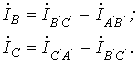
In accordance with 1 order. Kirchoff current in neutral. wire
With symmet. e.g.
When we carry e.g. ![]()
The neutral wire equalizes the phase voltages.
15I16 Operating modes of a three-phase receiver.
There are two types of connections: in a star and in a delta. In turn, when connected to a star, the system can be three- and four-wire.
star connection
On fig. 6 shows a three-phase system when connecting the phases of the generator and the load into a star. Here the wires AA', BB' and CC' are line wires.
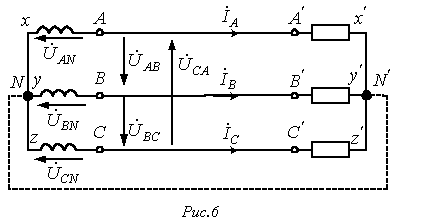
Linear called the wire connecting the beginning of the phases of the winding of the generator and receiver. The point at which the ends of the phases are connected to a common node is called neutral(in Fig. 6, N and N' are the neutral points of the generator and the load, respectively).
The wire connecting the neutral points of the generator and receiver is called neutral(shown in dotted line in Fig. 6). A three-phase system when connected to a star without a neutral wire is called three-wire, with neutral wire four-wire.
All quantities related to phases are called phase variables, to the line linear. As can be seen from the diagram in Fig. 6, when connected in a star line currents are equal to the corresponding phase currents. If there is a neutral wire, the current in the neutral wire ![]() . If the system of phase currents is symmetrical, then. Therefore, if the symmetry of the currents were guaranteed, then the neutral wire would not be needed. As will be shown below, neutral wire maintains the symmetry of the voltages on the load when the load itself is asymmetric.
. If the system of phase currents is symmetrical, then. Therefore, if the symmetry of the currents were guaranteed, then the neutral wire would not be needed. As will be shown below, neutral wire maintains the symmetry of the voltages on the load when the load itself is asymmetric.
Since the voltage at the source is opposite to the direction of its EMF, the phase voltages of the generator (see Fig. 6) act from points A, B and C to the neutral point N; ![]() - phase load voltages.
- phase load voltages.
Line voltages act between line conductors. In accordance with Kirchhoff's second law for line voltages, one can write ![]()
![]()
![]()

Note that always - as the sum of voltages in a closed loop.
On fig. 7 is a vector diagram for a symmetrical stress system. As its analysis shows (the rays of phase voltages form the sides of isosceles triangles with angles at the base equal to 300), in this case
It is usually taken into account in calculations ![]() . Then for the case direct phase sequence
. Then for the case direct phase sequence ![]() , (at reverse phase sequence phase shifts y are interchanged). With this in mind, on the basis of relations (1) ... (3), complexes of linear voltages can be determined. However, if the stresses are symmetrical, these quantities can be easily determined directly from vector diagram in fig. 7. Directing the real axis of the coordinate system along the vector (its initial phase is zero), we count the phase shifts of the linear voltages with respect to this axis, and their modules are determined in accordance with (4). So for linear voltages and we get:
, (at reverse phase sequence phase shifts y are interchanged). With this in mind, on the basis of relations (1) ... (3), complexes of linear voltages can be determined. However, if the stresses are symmetrical, these quantities can be easily determined directly from vector diagram in fig. 7. Directing the real axis of the coordinate system along the vector (its initial phase is zero), we count the phase shifts of the linear voltages with respect to this axis, and their modules are determined in accordance with (4). So for linear voltages and we get: ![]() ;
;![]() .
.
Triangle connection
Due to the fact that a significant part of the receivers included in three-phase circuits is unbalanced, it is very important in practice, for example, in circuits with lighting fixtures, ensure the independence of the operating modes of individual phases. In addition to four-wire, three-wire circuits also have similar properties when connecting the phases of the receiver into a triangle. But the phases of the generator can also be connected into a triangle (see Fig. 8).
For a symmetrical EMF system, we have
![]() .
.
Thus, in the absence of load in the generator phases in the circuit in Fig. 8 currents will be zero. However, if you swap the beginning and end of any of the phases, then a current will flow in the triangle short circuit. Therefore, for a triangle, it is necessary to strictly observe the order of connecting phases: the beginning of one phase is connected to the end of another.
The connection diagram of the generator and receiver phases in a triangle is shown in fig. 9.
Obviously, when connected to a triangle, the line voltages are equal to the corresponding phase voltages. According to the first Kirchhoff law, the relationship between the linear and phase currents of the receiver is determined by the relations
![]()

Similarly, you can express linear currents through the phase currents of the generator.
On fig. 10 shows a vector diagram of a symmetrical system of linear and phase currents. Its analysis shows that with the symmetry of the currents
In conclusion, we note that in addition to the star-star and triangle-delta connections considered, the star-triangle and triangle-star schemes are also used in practice.
Page 8 of 16
In a three-phase electrical network, linear and phase voltages are distinguished.
Linear (it is also called phase-to-phase or phase-to-phase) is the voltage between two phase wires.
Phase - between the neutral wire and one of the phase. Line voltages under normal operating conditions are the same and 1.73 times greater than phase voltages, i.e., the voltage between zero and phase wire(phase) is 58% of line voltage. Voltage three-phase network It is customary to evaluate the line voltage. For three-phase lines outgoing from the transformer substation, a nominal linear voltage of 380 V is set, which corresponds to a phase voltage of 220 V. In the designation of the nominal voltage of three-phase four-wire networks, both values \u200b\u200bare indicated, i.e. 380/220 V. This emphasizes that not only three-phase electrical receivers Rated voltage 380 V, but also single-phase at 220 V.
Three-phase system 380/220 V with grounded neutral the most widespread, but in some settlements and garden cooperatives, you can find other systems for distributing electricity. For example, three-phase with a linear voltage of 220 V and an ungrounded (isolated) neutral. Single-phase electrical receivers 220 V are connected to line voltage between any pair of phase wires, and three-phase - to three phase wires. With this system neutral wire not required, and an ungrounded neutral reduces the risk of electric shock in the event of an insulation failure. However, the detection of insulation faults in such a system is more difficult than with a grounded neutral.
Walkthrough electric current along the wires is accompanied by losses and the voltage at consumers turns out to be somewhat lower than at the beginning of the line at the transformer substation. In order to ensure acceptable voltage levels along the entire line, the voltage at the transformer substation has to be maintained above the nominal voltage, i.e. not 380/220 V, but 400/230 V. In electrical networks in rural areas, consumers, according to current standards, voltage deviations of 7 .5% of nominal value. This means that a voltage of 350–410 V is allowed on a three-phase power receiver, and 200–240 V on a single-phase one.
Voltage deviations. However, there are times when the magnitude of the voltage is out of acceptable limits. With a decrease in voltage, the intensity of electric lighting from incandescent lamps noticeably drops, and the performance of electrical heating appliances, the stability of the operation of televisions and other radio-electronic devices with power supply from the network is violated. An increase in voltage leads to premature failure of electric lamps and heating devices. Electric motors are less sensitive to voltage fluctuations.
In each branch of technology, one can always find a kind of echo of ancient times, namely, names that reflect a kind of history of the development of this direction. And few people know that this or that technical concept has a long way of becoming, getting used to, and at the very beginning of its birth it marked another, often very significant, step of technical progress. So, for example, among electrical terms one can often hear the expressions " three-phase voltage”, “line voltage”, “direct” or “alternating voltage” and many other items with the word “voltage”.
The most widespread in electrical engineering are networks AC voltage sinusoidal shape. The maximum value of the voltage during its fluctuation is called the amplitude Ua. For such a voltage, additional units of measurement are used - frequency F and phase ψ. The frequency is determined by the number of oscillations per unit time, and the phase is the time shift of the same oscillation points. It so happened historically that the term "phase" began to be called alternating voltage, if it is part of a system of many phases - usually three. were another achievement of electrical engineering and have so many advantages that it is simply impossible to pass by. And the most important of them is the ability to very simply, virtually without any effort, obtain a rotating magnetic field - the basic principle of operation of any electric motor. In distinguish between phase and linear voltage, and its feature is that each of the phases has a shift with respect to the other two +/- 120 degrees. voltage has output windings in which the phase shift is structurally specified. Each of the windings has an end and a beginning: H1-K1, H2-K2, H3-K3. IN three-phase system two options for connecting the phases are possible - "star" and "triangle".
When connecting a "star", all ends are connected to one point - "output 0", and the beginnings serve as output ends for the generator and input for the device powered by it. In such a system, the line voltage is the value measured between any pair of output ends H1, H2, H3 and is designated Ulin. There is another characteristic of a three-phase network - phase voltage. It is designated Uf and is measured between the points "0 output" and any of the output ends of K1, K2 and K3. Omitting details, it should be noted that, based on the vector diagram for a three-phase network, the relationship between these voltages is Ulin = V3 * Uf. When connecting the "triangle", the ends of the windings are connected in a ring: K1-H1-K2-H2-K3-H3-K1. Each connection "end - beginning" is a conclusion, and at the same time, the linear voltage does not differ from the phase voltage, i.e. Ulin = Uf. It is interesting to compare the constant voltage Udir and the amplitude of the alternating voltage Ua, for example, based on the same energy released in the load. For this case, Udir = V2 * Ua.
This is how knowledge about the essence and nature of electricity has been accumulating for decades, and the imperceptibly simple concept of “voltage” has acquired related terms that expand our capabilities in using natural phenomena for human needs.
 (1 ratings, on average: 5,00 out of 5)

