The use of feed-through capacitors in electromagnetic compatibility filters. What is a capacitor, types of capacitors and their designation in diagrams
Pass-through capacitors are not new in the electronics industry: they were discovered immediately after conventional double-plate capacitors and found application in high-frequency components of tube devices of communication equipment. Today, the importance of pass-through capacitors is presented in a new perspective.
Increasing the operating frequencies of digital integrated circuits is now the main sustainable trend in electronics. To reduce the influence of interference on device microcircuits, it is necessary to stabilize the supply voltage of high-frequency devices and reduce the impact of their operation on the rest of the electronic assembly (power decoupling).
Typically, multilayers are used for such purposes. ceramic capacitors, mounted directly in the power supply circuit of high-frequency units and next to multi-purpose microcircuits. At frequencies above 10 MHz, filtering efficiency pulsations drops sharply due to the impedance of the capacitor (its internal inductance) - series inductive reactance. And although practitioners install chip capacitors for power supply even at frequencies of 2...3 GHz and claim that there is no need to install smoothing capacitors at frequencies above 10 MHz (supposedly this effect can be neglected), we are talking about installing one highly efficient pass capacitor instead of several conventional chip capacitors. In cases where the power source is remote from microcircuits that operate with high-frequency signals, the installation of smoothing elements is necessary. Often seen on modern printed circuit boards“weighing” microcircuits operating at high frequencies with numerous chip capacitors connected parallel. Terminal (ceramic, disk and similar) capacitors cannot be used in this case due to the additional inductance of their terminals, which significantly affects the suppression of interference from the high-frequency unit. Interference and interference are especially well recorded by devices when the electronic high-frequency unit is removed from the power source.
To solve this problem, capacitor manufacturers produce special series of capacitors with the lowest possible equivalent inductance (ESL). In this case, the terminals of such chip capacitors are located along the long side of their housing, which makes it possible to reduce the equivalent inductance by approximately half compared to those types where the terminals are located on the short end sides of the housing.
However, if the device is intended to operate in a frequency range greater than 100 MHz, this approach is not sufficient. Japanese company "Murata" proposed its development of a series of three-terminal high-capacity pass-through capacitors. These are compact chip components measuring 2.0x1.25 mm based on the X7R dielectric.
A comparison of the capacitor of the new NFM18P series with a conventional multilayer ceramic capacitor in practice shows an almost 10-fold reduction in the impedance of the new type of capacitor at high frequencies above 100 MHz, associated with reduced structural inductance.
As an example, I will give a simple experiment that can be repeated in any equipped laboratory. You will need a power supply, a high-frequency oscilloscope and a generator with a frequency of 10 MHz, which you can assemble yourself with a technology chip CMOS. Let's connect any generator in parallel to a stabilized power source with a fixed constant voltage of 5 V. The author used a generator based on the KR1561LE5 microcircuit, which produces rectangular pulses at the output. The length of unshielded conductors from the power source to the generator is 1 m. Using an oscilloscope, we will record the level of high-frequency ripples at the power output of the microcircuit.
The ripple amplitude is approximately 1 V, and the frequency of this interference corresponds to the frequency of the generator output pulses. Now let’s connect a multilayer ceramic capacitor in parallel to the power pins of the microcircuit Murata MLCC 1206 X5R and take a look at the oscilloscope screen again. The interference is present, but its amplitude has decreased to 0.65 V. Now, instead of a multilayer capacitor with an X5R dielectric, we will turn on the pass capacitor NFM18PC105R (here the pass capacitor is included as a filter) and measure the readings with an oscilloscope at the same point - directly at the terminals of the capacitor installed near the microcircuits . The ripple level has been reduced to 0.3 V. Approximately the same effect is obtained if 10 multilayer ceramic capacitors of the brand MLCC 0201-2220 with dielectric X7R. One three-terminal capacitor of the NFM18P brand replaces ten double-plate (three-terminal output from the midpoint) multilayer capacitors in terms of high-frequency noise filtering quality. Moreover, if it is possible to change the generation frequency, you can make sure that as the frequency of high-frequency interference increases, the ripple level decreases, and vice versa
Of particular note is the high stability of capacitor capacitance in the range of 0.1-1 μF (thanks to the type of dielectric considered). Small dimensions, high load capacity (current up to 6 A), low impedance at frequencies above 10 MHz make the use of pass-through three-terminal capacitors effective and attractive in high-frequency components and practically so far have no alternative in modern compact devices, such as portable HF/microwave transmitters, radio stations, game consoles, computers and similar devices.
The table shows the main electrical characteristics some products.
Table. Basic electrical characteristics of three-terminal feed-through capacitors
|
Size, mm |
Capacity, µF |
Operating temperature range, C |
||||
|
-55 to +125 |
||||||
|
-55 to +125 |
||||||
|
-55 to +125 |
||||||
|
-55 to +125 |
||||||
|
-55 to +125 |
||||||
|
-55 to +125 |
||||||
|
-55 to +125 |
||||||
|
-55 to +125 |
||||||
|
from -20 to +80 |
from -55 to +85 |
|||||
|
from -55 to +85 |
||||||
|
from -20 to +80 |
from -55 to +85 |
|||||
|
from -20 to +80 |
from -55 to +85 |
Detailed reference data on high-capacity multilayer ceramic capacitors can be found in reference literature and on the Murata website.
Ceramic feed-through capacitors provide reliable protection from internal interference, and due to its compactness and simplified design of the circuit board, they are very suitable for use in electromagnetic compatibility (EMC) filters.
Electromagnetic interference that occurs during the operation of various electrical equipment is of two types - external and internal.
- External electromagnetic interference is interference from various external sources (for example, radios, high-voltage equipment and other devices). Special devices provide protection electrical systems from external interference, and ideally the source of external interference is also provided by an anti-interference system. Internal electromagnetic interference comes from electronic components located in one or adjacent electrical circuits. During operation, antennas, processors, software boards and other devices emit electromagnetic waves, which propagate along printed conductors and interfere with information signals, distorting them. However, it often happens that to exclude from electrical circuit source of interference is impossible, since the system will not work.
EMC filters allow electrical isolation of sources of interference from equipment that needs to be protected from this interference without affecting the functionality of the system. They eliminate interference by discharging their signals to ground. EMC filters help protect electrical equipment from both internal and external interference and prevent interference from propagating along printed circuit conductors.
Electromagnetic interference protection is usually achieved using passive components. As EMC requirements become more stringent, there is a need to improve the EMC properties of passive components.
EMC filters are based on capacitors, as well as LC or RC circuits. Filters based on LC and RC circuits do not always provide the required reduction in noise levels; they have a complex design and require a lot of space for installation. Filters based on standard ceramic capacitors also take up a lot of space and do not sufficiently reduce the level of noise in electrical circuits.
Feed-through ceramic capacitors provide reliable EMI protection and are ideal for EMC filters. With their help, you can perform good filtering and reduce interference at radio frequencies; they have compact sizes (0805 or 1206) and a simple design.
Feedthrough capacitors are made from the same material (COG, X7R) as standard ceramic capacitors, are manufactured using the same technology and have similar technical advantages: ease of operation, compact design and a wide range of operating temperatures.
Unlike standard ones, pass-through capacitors have 3 poles (4 external terminals). There is no capacitance between the 1st and 2nd poles of this capacitor (pass capacitor), but between the 1st and 3rd or 2nd and 3rd poles there is. The basic design of a pass capacitor is shown in Fig. 1, and its graphical representation is in the diagram (Fig. 2).
The operating diagram of such a capacitor is quite simple. The signal, along with the noise superimposed on it, arrives at pole 1 (input) of the capacitor. Interference is filtered out using a capacitor and discharged to ground through pole 3 (ground). The signal, cleared of interference, leaves the capacitor through pole 2 (output). A set of noise-suppressing pass capacitors is shown in Fig. 3. Capacitor sets must be used in cases where several communication lines are connected to equipment protected by an EMC filter. Using feed-through capacitor kits reduces installation time for the EMC filter and saves space on the printed circuit board.
A standard X7R capacitor with frame size 1206 and a nominal capacitance of 2.2 nF gives a maximum insertion attenuation of 36 dB and has a resonant frequency of about 120 MHz (Fig. 6), while a pass capacitor of the same material, with the same frame size housing and capacitance introduces a maximum attenuation of 45 dB, and its resonant frequency is approximately 280 MHz.
A similar situation is observed when higher value nominal capacitance (Fig. 7): the insertion attenuation is higher, but the resonant frequency decreases due to the increase in capacitance.
So, feed-through capacitors are great for use in EMC filters. The main properties of these capacitors:
- low electrical losses; significant suppression of interference; operation at radio frequencies; compactness; wide range of operating temperatures -40 ... +125 C; low cost compared to complex noise filters based on filter circuits.
Due to their properties, feed-through ceramic capacitors are widely used in various areas: automotive electronics, telecommunications, personal computers, laptop computers, industrial electronics, mobile phones and many others.
Magnetron power supply, in microwave oven, is carried out through a built-in filter, which consists of two inductors and two pass capacitors. This filter is designed to filter the magnetron supply voltage. Appearance and the filter circuit are shown in Figure 1., and it works approximately the same as.
Picture 1
We will not dwell on the topic of determining the malfunction of capacitors here; you can read about this in the article; we will only consider the process of replacing feed-through capacitors. The feed-through capacitors of the magnetron are placed in plastic case with a flange for fastening (Figure 2 - right side). The conductors connected to the outermost (according to the diagram) plates of the capacitors are brought out under the power terminals on one side, and under the leads for connection to the filter coils on the other. The second plate of each capacitor, inside the housing, is connected to the mounting flange. The entire structure is not dismountable and additionally serves as an insulator for the magnetron power supply terminals. The capacitor mounting flange is located inside the filter box and is attached to it using elongated rivets and fastening tabs. The terminals of the capacitors and the filter coil are connected using resistance welding.
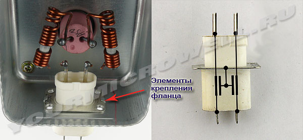
Figure 2
Any operation to replace a faulty element can be divided into two stages: dismantling the faulty element and then installing a new one. To dismantle faulty capacitors you must:
- Remove the magnetron filter box cover.
- Disconnect the leads of the filter coils from the leads of the capacitors (Figure 2). To do this, use side cutters and bite off the coil leads as close as possible to the spot welding site.
- Bend the fastening tabs. Pry up the capacitor mounting flange with a flat, sharp tool and disconnect the riveted connection.
- Remove faulty capacitors.
That's all, dismantling is complete. All that remains is to install the new part.
The installation process will be somewhat more interesting.
- Before installing working capacitors, thoroughly clean the terminals of the filter coils (remove the enamel from the wire). If you took capacitors as a donor from an old magnetron that failed for another reason, then remove the contact welding residues from the terminals and clean them just as thoroughly using a needle file or sandpaper.
- Next, you need to install the working element in its place and securely connect the capacitor mounting flange to the magnetron housing. If attempts to secure the flange using native fasteners do not lead to anything good, try another method. The flange can be placed outside the filter box and tightened using self-tapping screws of suitable length and diameter, screwing them into the rivet holes. For these purposes, you can also use ordinary M3 screws with nuts. The location of the flange relative to the filter box housing (inside or outside) will not affect the operation of the magnetron in any way. The main thing is reliable contact.
- Then, we bend the leads of the filter coils, place them on the leads of the capacitors and connect them using resistance welding.
- Close the filter box with a lid. That's it, the magnetron is ready for use.
It's simple, isn't it? But, probably, it’s just only for the happy owners of resistance welding machines, and I’m sure there are a minority of those among those reading this article. The rest are probably very confused by the third installation point. Indeed, it is not so easy to reliably connect capacitors to coils without using resistance welding. The first thing that comes to mind is to use regular soldering iron and solder the leads together. This connection method will help, but not for long. The fact is that when the magnetron operates, quite a lot of heat is released. Both the magnetron housing and all its structural elements, including filter parts, heat up. This temperature, of course, does not reach the melting point of the solder (approximately 300 degrees C), but it is quite enough to destroy the mechanical strength of the solder. After prolonged operation of the furnace, the solder will soften, and then even the slightest vibration, for example, from the operation of a fan, will complete the destructive process. The leads will fall apart and the oven will stop working again.
I would like to suggest two ways to solve this problem. Both methods have been successfully used in practice more than once. In the first case, we will still use a soldering iron. But, we will use not just soldering, but reinforced soldering. To do this, in the third installation step we perform the following steps:
A) We bend the free leads of the filter coils so that they intersect with the leads of the capacitors at a right angle (or approximately so). You may have to unwind one turn of the coil to do this. This will of course change the filter parameters somewhat, but not critically. Both conclusions must be thoroughly cleaned before this.
B) We take a small piece of ordinary, stranded (always stranded!) installation wire. We clean it of insulation. Then, using a cleaned wire, we wind the terminals of the filter coils to the terminals of the capacitors crosswise and twist them. The twist should be as tight as possible. Use side cutters to remove excess wire.
C) Using a well-heated soldering iron, carefully warm up the twisted area and fill it with solder. Thorough heating is very important; the molten solder should flow between almost every wire of the mounting wire and be evenly distributed throughout the soldering area. During the soldering process, do not skimp on flux - rosin. If during heating the solder does not spread, but turns out to be something like porridge, then you should increase the temperature of the soldering iron tip or use a more powerful one. Otherwise the connection will not be reliable.
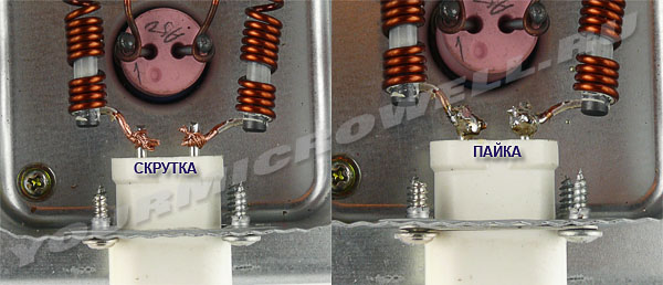
Figure 3
It should look something similar to what is shown in Figure 3 on the right. It doesn't look very aesthetically pleasing, but it's quite reliable. Anyone who is concerned about the aesthetic side of this issue can, if desired, treat the soldering area with a needle file or file, giving the connection a more attractive appearance. This soldering method allows you to slightly increase the heat capacity of the joint and significantly increase its mechanical strength.
In the second method everything is much simpler. Put the soldering iron aside and do the following:
A) Just like in the first method, we clear the conclusions. We bend the terminals of the coils, but now we place them end-to-end with the terminals of the capacitors.
B) We take two connectors with screws, such as those shown in Figure 4 on the left or others, but suitable for internal diameter. We remove them from isolation.
C) We put the connectors with one end on the terminals of the capacitors, and the other on the terminals of the coils. Tighten the mounting screws.
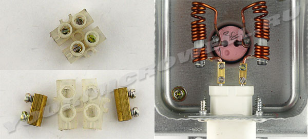
Figure 4
The output should look like shown in Figure 4 on the right. In order to avoid spontaneous loosening of the connector screws under the influence of vibration during operation of the oven, each screw should be secured with a drop of heat-resistant varnish or paint. After completing step 4 for installation, the process of replacing feed-through capacitors can be considered complete. In both the first and second cases, the magnetron is ready for further operation.
Of course, someone can use other, perhaps even better, methods for replacing feed-through capacitors. But in this article, I just shared my personal experience. In practice, to be honest, I mostly used the first replacement method. Not a single microwave oven repaired this way has ever been returned. I will be very glad if in this article you find answers to your questions. Good luck with the repair, Gentlemen!
Page 1
Pass-through capacitors are used mainly in power supply circuits of high-frequency stages of equipment. In this case, the capacitor, using the bushing mentioned above, is attached to the hole in the metal screen (chassis, panel) of the cascade or unit, in the power circuit of which filtering of the high-frequency component is necessary; The bushing ensures reliable contact of the outer lining of the capacitor with the screen. A power current is supplied to one end of the middle rod, and a load is connected to the other.
Feed-through capacitors provide effective filtering of power supply circuits.
Pass-through capacitors are used as anti-interference capacitors in power circuits, for example, to eliminate interference to radio reception caused by sparking brushes electric machines. To do this, the current-carrying wire from the power source creating interference is connected to one end of the KBP capacitor rod, and the wire from the load is connected to the other end of the rod. In this case, the operating current (direct or alternating) from the power source passes to the load along the capacitor rod, and most of The high-frequency interference current is shorted through the capacitor to the housing, since the capacitance of the capacitor for the high-frequency interference current is small. Even if the operating alternating current has a higher frequency (on the order of hundreds of hertz), the capacitance of the capacitor for this current is much higher than for the high-frequency interference current.
Pass-through capacitors are used to filter high-frequency currents in power circuits and for various blocking applications, the action of which must be effective over a very wide frequency range.
Pass-through capacitors C, which provide decoupling of the control circuit from external circuits by control current, can be designed differently depending on the frequency range, in particular, in the form of a design gap in the current-carrying conductor. When using microstrip lines, pass capacitors are installed in the gap between the strip conductors and can provide an SWR of no more than 1 05 in a wide frequency band reaching several octaves. Blocking capacitors Sb are designed to decouple the switch channels from the power circuits, and also to ensure that the input impedance of the power source does not affect the transmission of microwave energy through the switch.
Feed-through capacitors SZ, C4 and C5 prevent high-frequency oscillations from the generator compartment from entering the low-frequency circuits, as well as the emission of radio interference.
Capacitors(from Lat. condenso - I compact, thicken) - these are radioelements with concentrated electrical capacity, formed by two or more electrodes (plates) separated by a dielectric (special thin paper, mica, ceramics, etc.). The capacitance of the capacitor depends on the size (area) of the plates, the distance between them and the properties of the dielectric.
An important property of a capacitor is that for alternating current he is resistance, the value of which decreases with increasing frequency.
The main units for measuring the capacitance of capacitors are: Farad, microFarad, nanoFarad, picofarad, the designations on capacitors for which look like: F, μF, nF, pF.
Like resistors, capacitors are divided into capacitors of constant capacitance, capacitors of variable capacitance (VCA), tuning and self-regulating capacitors. The most common are fixed capacitors.
They are used in oscillating circuits, various filters, as well as for separating DC and AC circuits and as blocking elements.
Fixed capacitors
Conditional graphic designation of a constant capacitor - two parallel lines - symbolizes its main parts: two plates and a dielectric between them (Fig. 1).
Rice. 1. Fixed capacitors and their designation.
Near the capacitor designation on the diagram, its nominal capacity is usually indicated, and sometimes Rated voltage. The basic unit of capacitance is the farad (F) - the capacitance of such an isolated conductor, the potential of which increases by one volt with an increase in charge by one coulomb.
This is a very large value, which is not used in practice. In radio engineering, capacitors with capacities ranging from fractions of a picofarad (pF) to tens of thousands of microfarads (μF) are used. Recall that 1 µF is equal to one millionth of a farad, and 1 pF is one millionth of a microfarad or one trillionth of a farad.
According to GOST 2.702-75, the nominal capacitance from 0 to 9,999 pF is indicated on the circuits in picofarads without designating the unit of measurement, from 10,000 pF to 9,999 μF - in microfarads with the designation of the unit of measurement by the letters mk (Fig. 2).
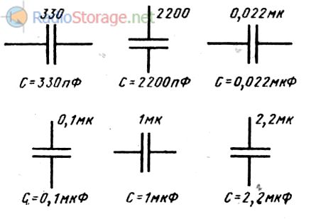
Rice. 2. Designation of units of measurement for capacitance of capacitors in the diagrams.
Capacitance designation on capacitors
The rated capacitance and the permissible deviation from it, and in some cases the rated voltage, are indicated on the capacitor housings.
Depending on their size, the nominal capacity and permissible deviation are indicated in full or abbreviated (coded) form.
The full designation of capacitance consists of the corresponding number and unit of measurement, and, as in the diagrams, capacitance from 0 to 9,999 pF is indicated in picofarads (22 pF, 3,300 pF, etc.), and from 0.01 to 9,999 µF - in microfarads (0.047 µF, 10 µF, etc.).
In abbreviated marking, the units of measurement of capacitance are designated by the letters P (picofarad), M (microfarad) and N (nanofarad; 1 nano-farad = 1000 pF = 0.001 μF).
Wherein Capacitance from 0 to 100 pF is indicated in picofarads, placing the letter P either after the number (if it is an integer) or in place of the decimal point (4.7 pF - 4P7; 8.2 pF - 8P2; 22 pF - 22P; 91 pF - 91P, etc.).
Capacitance from 100 pF (0.1 nF) to 0.1 µF (100 nF) is indicated in nanofarads, and from 0.1 µF and above - in microfarads.
In this case, if the capacitance is expressed in fractions of a nanofarad or microfarad, the corresponding the unit of measurement is placed in place of zero and comma(180 pF = 0.18 nF - H18; 470 pF = 0.47 nF - H47; 0.33 µF - MZZ; 0.5 µF - MbO, etc.), and if the number consists of an integer part and a fraction - at the decimal point (1500 pF = 1.5 nF - 1H5; 6.8 µF - 6M8, etc.).
Capacitances of capacitors, expressed as an integer number of corresponding units of measurement, are indicated in the usual way (0.01 μF - 10N, 20 μF - 20M, 100 μF - 100M, etc.). To indicate the permissible deviation of capacitance from the nominal value, the same coded designations are used as for resistors.
Features and requirements for capacitors
Depending on the circuit in which capacitors are used, different requirements apply to them. requirements. Thus, a capacitor operating in an oscillating circuit must have low losses across operating frequency, high stability of the container over time and with changes in temperature, humidity, pressure, etc.
Capacitor losses, determined mainly by losses in the dielectric, increase with increasing temperature, humidity and frequency. Capacitors with a dielectric made of high-frequency ceramics, with mica and film dielectrics have the lowest losses, while capacitors with a paper dielectric and ferroelectric ceramics have the highest losses.
This circumstance must be taken into account when replacing capacitors in radio equipment. Change in capacitance of a capacitor under the influence of environment(mainly its temperature) occurs due to changes in the dimensions of the plates, the gaps between them and the properties of the dielectric.
Depending on the design and dielectric used, capacitors are characterized by different temperature coefficient of the container(TKE), which shows the relative change in capacitance with a change in temperature by one degree; TKE can be positive or negative. Based on the value and sign of this parameter, capacitors are divided into groups, which are assigned the corresponding letter designations and body paint color.
To maintain the tuning of oscillatory circuits when operating over a wide temperature range, sequential and parallel connection capacitors in which TKE have different signs. Due to this, when the temperature changes, the tuning frequency of such a temperature-compensated circuit remains practically unchanged.
Like any conductors, capacitors have some inductance. The longer and thinner the capacitor leads are, the greater the larger sizes its plates and internal connecting conductors.
They have the highest inductance paper capacitors, in which the facings are made in the form of long strips of foil, rolled together with the dielectric into a round or other shaped roll. Unless special measures are taken, such capacitors do not perform well at frequencies above a few megahertz.
Therefore, in practice, to ensure the operation of the blocking capacitor in a wide frequency range, a ceramic or mica capacitor of small capacity is connected in parallel with the paper capacitor.
However, there are paper capacitors with low self-inductance. In them, strips of foil are connected to the terminals not in one, but in many places. This is achieved either by strips of foil inserted into the roll during winding, or by moving the strips (linings) to opposite ends of the roll and soldering them (Fig. 1).
Feed-through and reference capacitors
To protect against interference that can penetrate into the device through the power supply circuits and vice versa, as well as for various interlocks, so-called pass capacitors. Such a capacitor has three terminals, two of which are a solid current-carrying rod passing through the capacitor body.
One of the capacitor plates is attached to this rod. The third conclusion is metal case, to which the second plate is connected. The body of the pass-through capacitor is fixed directly to the chassis or screen, and the current-carrying wire (power circuit) is soldered to its middle terminal.
Thanks to this design, high-frequency currents are connected to the chassis or screen of the device, while direct currents pass unhindered.
Used at high frequencies ceramic feed-through capacitors, in which the role of one of the plates is played by the central conductor itself, and the other is the metallization layer deposited on the ceramic tube. These design features are also reflected by the conventional graphic designation of a pass-through capacitor (Fig. 3).
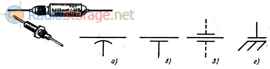
Rice. 3. Appearance and image on the diagrams of feed-through and support capacitors.
The outer lining is designated either in the form of a short arc (a), or in the form of one (b) or two (c) straight line segments with leads from the middle. The last designation is used when depicting a pass-through capacitor in the screen wall.
For the same purpose as checkpoints, they are used reference capacitors, which are a kind of mounting racks mounted on a metal chassis. The plate connected to it is distinguished in the designation of such a capacitor by three inclined lines, symbolizing “grounding” (Fig. 3d).
Oxide capacitors
To operate in the audio frequency range, as well as to filter rectified supply voltages, capacitors are needed, the capacitance of which is measured in tens, hundreds and even thousands of microfarads.
Such capacity with sufficiently small dimensions has oxide capacitors(old name - electrolytic). In them, the role of one plate (anode) is played by an aluminum or tantalum electrode, the role of a dielectric is played by a thin oxide layer deposited on it, and the role of the other plate (cathode) is a special electrolyte, the output of which is often the metal body of the capacitor.
Unlike others most types of oxide capacitors are polar, i.e. they require for normal operation polarizing voltage. This means that they can only be switched on in DC or pulsating voltage circuits and only in the polarity (cathode to minus, anode to plus) indicated on the housing.
Failure to comply with this condition leads to failure of the capacitor, which is sometimes accompanied by an explosion!
Oxide capacitor switching polarity are shown in the diagrams with a “+” sign, depicted near the plate that symbolizes the anode (Fig. 4,a).
This is the general designation for a polarized capacitor. Along with it, specifically for oxide capacitors, GOST 2.728-74 established a symbol in which the Positive plate is depicted as a narrow rectangle (Fig. 4.6), and the “+” sign can be omitted in this case.
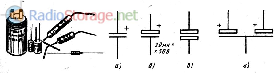
Rice. 4. Oxide capacitors and their designation on circuit diagrams.
In circuits of radio-electronic devices, you can sometimes find the designation of an oxide capacitor in the form of two narrow rectangles (Fig. 4, c). This is a symbol of a non-polar oxide capacitor that can operate in alternating current circuits (i.e. without polarizing voltage).
Oxide capacitors are very sensitive to overvoltage, so diagrams often indicate not only their rated capacitance, but also their rated voltage.
In order to reduce the size, two capacitors are sometimes placed in one housing, but only three leads are made (one is common). The symbol of a dual capacitor clearly conveys this idea (Fig. 4d).
Variable capacitors (VCA)
Variable capacitor consists of two groups metal plates, one of which can move smoothly relative to the other. During this movement, the plates of the moving part (rotor) are usually inserted into the gaps between the plates of the stationary part (stator), as a result of which the area of overlap of one plate by another, and therefore the capacitance, changes.
Dielectric In the KPI, air is most often used. In small-sized equipment, for example, in transistor pocket receivers, CPE with a solid dielectric, which is used as films of wear-resistant high-frequency dielectrics (fluoroplastic, polyethylene, etc.), are widely used.
The parameters of PCBs with a solid dielectric are somewhat worse, but they are much cheaper to produce and their dimensions are much smaller than PCBs with an air dielectric.
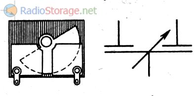
WITH symbol We have already met KPI - this is the symbol of a constant-capacity capacitor crossed out by a regulation sign. However, from this designation it is not clear which of the plates symbolizes the rotor and which symbolizes the stator. To show this in the diagram, the rotor is depicted as an arc (Fig. 5).
Rice. 5. Designation of variable capacitors.
The main parameters of the KPI, which allow us to evaluate its capabilities when operating in an oscillatory circuit, are the minimum and maximum capacitance, which, as a rule, are indicated on the diagram next to the KPI symbol.
In most radio receivers and radio transmitters, KPI blocks consisting of two, three or more sections are used to simultaneously tune several oscillatory circuits.
The rotors in such blocks are mounted on one common shaft, by rotating which you can simultaneously change the capacity of all sections. The outer plates of the rotors are often split (along the radius). This allows you to adjust the unit at the factory so that the capacities of all sections are the same in any position of the rotor.
The capacitors included in the KPI block are shown separately in the diagrams. To show that they are combined into a block, i.e., controlled by one common handle, arrows indicating regulation are connected by a dashed line of mechanical connection, as shown in Fig. 6.
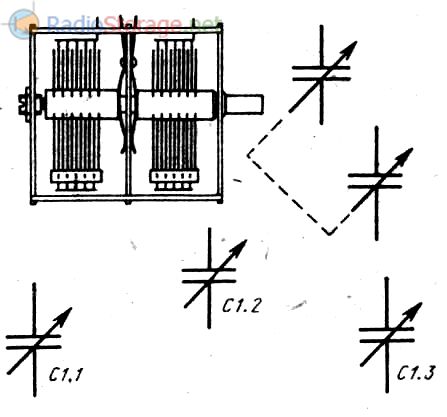
Rice. 6. Designation of dual variable capacitors.
When depicting the block's KPIs in different parts of the diagram that are far apart from each other, the mechanical connection is not shown, limiting itself only to the corresponding numbering of sections in the position designation (Fig. 6, sections C 1.1, C 1.2 and C 1.3).
In measuring equipment, for example in the arms of capacitive bridges, so-called differential capacitors(from Latin differentia - difference).
They have two groups of stator and one rotor plates, arranged so that when the rotor plates exit the gaps between the plates of one stator group, they at the same time enter between the plates of the other.
In this case, the capacitance between the plates of the first stator and the rotor plates decreases, and between the plates of the rotor and the second stator increases. The total capacitance between the rotor and both stators remains unchanged. Such capacitors are depicted in diagrams, as shown in Fig. 7.
Rice. 7. Differential capacitors and their designation on the diagrams.
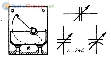
Trimmer capacitors. To set the initial capacitance of the oscillating circuit, which determines the maximum frequency of its tuning, tuning capacitors are used, the capacitance of which can be changed from a few picofarads to several tens of picofarads (sometimes more).
The main requirement for them is a smooth change in capacity and reliable fixation of the rotor in the position set during adjustment. The axes of trimming capacitors (usually short) have a slot, so adjusting their capacitance is only possible with the use of a tool (screwdriver). In broadcasting equipment, capacitors with a solid dielectric are most widely used.
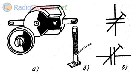
Rice. 8. Trimmer capacitors and their designation.
Ceramic design trimmer capacitor(PDA) of one of the most common types is shown in Fig. 8, a. It consists of a ceramic base (stator) and a ceramic disk (rotor) movably mounted on it.
The capacitor plates—thin layers of silver—are applied by burning onto the stator and outer side rotor. The capacity is changed by rotating the rotor. In the simplest equipment, wire tuning capacitors are sometimes used.
Such an element consists of a segment copper wire with a diameter of 1 ... 2 and a length of 15 ... 20 mm, on which it is wound tightly, turn to turn insulated wire with a diameter of 0.2... 0.3 mm (Fig. 8,b). The container is changed by unwinding the wire, and to prevent the winding from slipping, it is impregnated with some kind of insulating compound (varnish, glue, etc.).
Trimmer capacitors denoted on the diagrams by the main symbol crossed out by the tuning control sign (Fig. 8, c).
Self-regulating capacitors
Using special ceramics as a dielectric, the dielectric constant which strongly depends on the tension electric field, you can get a capacitor whose capacitance depends on the voltage on its plates.
Such capacitors are called varicondas(from English words vari (able) - variable and cond (enser) - capacitor). When the voltage changes from a few volts to rated capacity variconda changes 3-6 times.
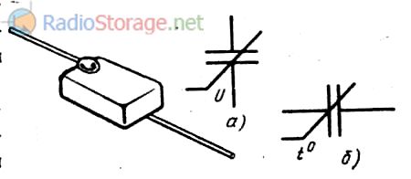
Rice. 9. Varicond and its designation on the diagrams.
Varicondas can be used in various automation devices, in swing frequency generators, modulators, for electrical adjustment of oscillatory circuits, etc.
Symbol for variconda- a capacitor symbol with a sign of nonlinear self-regulation and the Latin letter U (Fig. 9, a).
The designation of thermal capacitors used in electronic devices is constructed in a similar way. wristwatch. The factor that changes the capacitance of such a capacitor—the temperature of the medium—is designated by the symbol t° (Fig. 9, b). However, what is a capacitor is often searched for
Literature: V.V. Frolov, Language of radio circuits, Moscow, 1998.
 (1 ratings, on average: 5,00 out of 5)