Capacitor charging time. Relative dielectric constant. Capacitor device. What does capacity depend on?
Capacitoris an element electrical circuit, which is capable of accumulating electric charge. Important feature The property of a capacitor is not only to accumulate, but also to release charge, almost instantly.
According to the second law of commutation, the voltage across a capacitor cannot change abruptly. This feature is actively used in various filters, stabilizers, integrating circuits, oscillatory circuits, etc.
But there are other components that serve to accumulate electrical energy, namely the capacitor that we will introduce today and the inductor that we will introduce later. These two components form a group called "reagents", and when they are ideal, that is, they have no losses, which can be considered resistive components, never heat up. They accumulate and exchange energy between them.
Remember when we charge a metal body with positive and negative charges? And then we connect them to a metal rod. The organs were discharged by circulating electrons from the negative to the positive body until both were in the same electric potential. Internal structure The capacitor reminds us of this experience. In fig. 1 you can see two metal balls forming an elemental capacitor.
The fact that voltage cannot change instantly can be seen from the formula
If the voltage at the moment of switching changed abruptly, this would mean that the rate of change du/dt = ∞, which cannot happen in nature, since a source of infinite power would be required.
Capacitor charging process

With the help of this simple device we're going to establish some very precise concepts. To charge our device, we can keep its top bar on the positive end of the battery and its terminal below the negative one. Immediately, electrons circulate from the stack to the lower ball and from the upper ball to the stack.
This circulation is only instantaneous when the bars are maintained; after some time the circulation stops because a balance of charges has occurred. If we could measure the voltage between two rods using an infinite meter internal resistance, we would notice that the metal balls have a potential difference, equal to voltage cells.
The diagram shows an RC (integrating) circuit powered from a constant power source. When the key is closed to position 1, the capacitor is charged. The current passes through the circuit: “plus” of the source – resistor – capacitor – “minus” of the source.
The voltage on the capacitor plates changes exponentially. The current flowing through the capacitor also changes exponentially. Moreover, these changes are reciprocal; the higher the voltage, the less current flowing through the capacitor. When the voltage on the capacitor is equal to the source voltage, the charging process will stop and the current in the circuit will stop flowing.
The most interesting thing is that the voltage at which the elementary capacitor was charged is never lost even after disconnecting the device from the battery. If the formed capacitor is perfect and the meter has infinite resistance, it can measure the same voltage every other hour.
As you know from our specialty, everyone has a representation through a diagram. In Figure 2 we can observe a representation of our elementary capacitor with a very characteristic shape forming a circuit that will allow us to charge and discharge the capacitor. The element that converts the charge circuit into a discharge circuit is called an inverter switch and has a metal foil that is in physical contact with one or another section of the circuit.

Now, if we switch the key to position 2, then the current will flow in the opposite direction, namely through the circuit: capacitor - resistor - “minus” of the source. This will discharge the capacitor. The process will also be exponential.
An important characteristic of this circuit is the product R.C., which is also called time constantτ . During time τ, the capacitor is charged or discharged by 63%. In 5 τ, the capacitor gives up or receives the charge completely.
This is a difficult circuit for a beginner; so let's explain it in detail. These blades rotate on the two terminals on the left and alternately connect the top or bottom terminals on the right. Luis Davila with the title "Using a Multimeter". In fact, an oscilloscope allows you to watch how the voltage changes across a capacitor over time. We can say that it is a density plotter, equivalent to measuring with a counter every second and plotting the result.
Explaining a procedure in words is extremely tedious, so we use a procedure summarized in symbolic form. Finally, left-click on the battery transfer and drop down to the desktop where you want to find the battery. Then go to the diagram as indicated in the previous lesson.
Let's move on from theory to practice. Let's take a 0.47 uF capacitor and a 10 kOhm resistor.
Let's calculate the approximate time for which the capacitor should charge.
Now let's collect this diagram in multisim and try to simulate
![]()
The assembled circuit is powered by a 12 V battery. By changing the position of switch S1, we first charge and then discharge the capacitor through a resistance R = 10 KOhm. To clearly see how the circuit works, watch the video below.
After assembling the circuit or at the moment of gluing each component, you need to assign it a value. Double click on the selected component and a dialog box will appear as shown in the figure. In the same way, we double click on the capacitor and the dialog box in Figure 5 will appear with the power units. To do this, select the icon with the colored stripes and then open the graphic below the outline. When you click on the image, a screen appears that allows you to select scales.
Predisposing him to the next drawing. The desired plot can be seen in Figure 7. In fact, the capacitor does not discharge, ever remaining charged with a value that drops 38.4% from the value having 1 µS before. This type of curve is called exponential and always occurs when a reactive component combines with a resistive component. In our charge and discharge circuit, we use a double switch to disconnect the two terminals of our capacitor.
One of the most frequently used electronic components are capacitors. And in this article we will have to figure out what they consist of, how they work and what they are used for :)
Capacitor Charge Curve
In fact, both the negative terminal of the battery and the lower terminal of the resistor and the lower terminal of the capacitor can be permanently connected to ground, as this is enough to interrupt at one point in the circuit to stop the current. Just as a capacitor discharges exponentially, it also charges exponentially when there is a resistor between the battery and the capacitor known value. In fig. 10, a circuit can be observed in which the capacitor is charged from a 10V source or discharged to ground when the switch is moved.
Let's first look at capacitor device, and then we will smoothly move on to their main types and characteristics, as well as to the charging/discharging processes. As you can see, we have a lot of interesting things to explore today 😉
So, simple capacitor consists of two flat conducting plates located parallel to each other and separated by a dielectric layer. Moreover, the distance between the plates should be much smaller than, in fact, the dimensions of the plates:
When the switch is raised the capacitor is charged and the voltage rises, when it falls the resistor is connected and the voltage is low. Here we need to explain two very important things about simulation. You can actually select the key you want because by double-clicking the key, a dialog box will appear that will ask you which key you want to control. Secondly, it is impossible to open and close a key in two millionths of a second. Of course we take seconds between pressed and pressed.
It happens that the simulation does not run in real time. In fact, the circuit is not actually assembled, but solves equations, but at such a speed that they can be represented on a graph; although not in real time. The simulated time can be read at the bottom of the screen where it says "time". Can you easily explain why the voltage changes exponentially as a capacitor discharges? You must use mathematics to prove this, but it is preferable to anticipate the motive before performing a purely academic demonstration.

Such a device is called flat capacitor, and the plates - capacitor plates. It is worth clarifying that here we are considering an already charged capacitor (we will study the charging process itself a little later), that is, a certain charge is concentrated on the plates. Moreover, the greatest interest is in the case when the charges of the capacitor plates are identical in magnitude and opposite in sign (as in the figure).
Analyzing our example, we can say that when a capacitor is charged at 10V and a 1 ohm resistor is connected across it, the current flowing through the resistor is 10A and therefore the voltage drop across the resistor is equal to the source voltage. When a capacitor discharges across a resistor, the voltage is less and therefore each time it draws less current, and then it makes sense that the capacitor takes longer to discharge. For example, when a microsecond passed a voltage of 3.8 V and only a resistance of 3.8 A by a resistor.
Is it possible to charge a capacitor linearly? Sure, but it must be charged by a constant current source, not a constant voltage source like a battery. What is a constant current source? A constant voltage source is a voltage whose output voltage does not change with the load current. Instead the source direct current is any source that provides a constant output current regardless of load resistance. For example, a 1A DC source will deliver this current either into a 1 ohm charge or into a 10 ohm load.
And since the charge is concentrated on the plates, a electric field, depicted by arrows in our diagram. The field of a flat capacitor is mainly concentrated between the plates, however, an electric field also arises in the surrounding space, which is called a leakage field. Very often its influence in tasks is neglected, but you should not forget about it :)
Note that when charging a capacitor at constant current, the exponential curve converts to a straight line, resulting in many useful schemes, which we gradually learn. The same result can be obtained using the DC source symbol. In fact, if you want, you can consider DC supplies to be just an electronic abstraction, since they don't exist as a real component. As shown in FIG. 11, circuit change can work with constant current source.
Because the student can observe that the circuits generate the same signal across the capacitor and are therefore equivalent. In this lesson we met the second most important character in electronics. In fact, we are only presenting it because we have not yet explained how a real capacitor is made.
To determine the magnitude of this field, consider another schematic illustration flat capacitor:
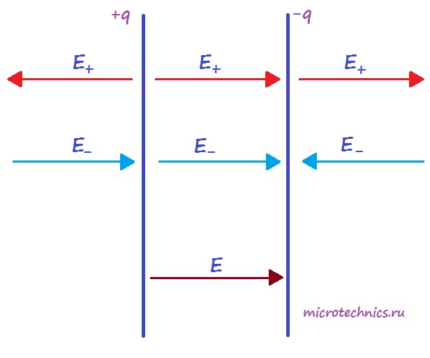
Each of the capacitor plates individually creates an electric field:
The expression for the field strength of a uniformly charged plate is as follows:
So far our capacitor is two metal balls separated by an insulator, which is air. We never specify the size of these balls needed to create a 1uF capacitor like the one we used in the explanation. This capacitor should have a diameter of about several kilometers. But fortunately, the current industry offers us solutions as small as a cylinder with a diameter of 3 mm by 3 heights.
In the next lesson we will finish the topic explaining what it is ceramic capacitor, polyester and electrolytic capacitor, and first of all, we will focus on the last one, because it is one of the components with highest level failures and for the fact that it has the peculiarity of being a polarized component.
Here is the surface charge density: . A is the dielectric constant of the dielectric located between the plates of the capacitor. Since the area of the capacitor plates is the same, as well as the amount of charge, then the voltage modules electric field, are equal to each other:
![]()
We have flat capacitor circular radio plates separated by distance. Current flows into the capacitor. Calculate the bias current inside the capacitor. This electric field is time dependent, and the displacement current is proportional to the time derivative of the electric flux of this field. This is because the charge carrying the current cannot pass through the capacitor and is deposited on the capacitor plate.
We then assume that the electric field between the plates of the capacitor is uniform and perpendicular to the plates. The vector is a unit vector that comes from the positive to the negative plate. In paragraph 2 we saw that the field created between two plates with charge densities of the same absolute value and opposite signs, was.
But the directions of the vectors are different - inside the capacitor the vectors are directed in one direction, and outside - in the opposite direction. Thus, inside the plates the resulting field is defined as follows:
What will be the voltage outside the capacitor? And everything is simple - to the left and right of the plates, the fields of the plates compensate each other and the resulting tension is 0 :)
Where σ is the surface charge density. The area of the plates is the capacitor. Then the electric field between the plates can be written down. Let's calculate the bias current flowing through the capacitor. The electric flux through the surface parallel to the plates is.
Since the electric field is uniform, we have. Displacement current. But this value is equal to the current that reaches the plates. We then see that the bias current between the plates of the capacitor is equal to the conduction current in the cable. This fact makes the Ampere-Maxwell law applicable to any surface supported by a closed curve.
Processes of charging and discharging capacitors.
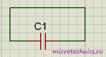
We've figured out the device, now let's figure out what happens if we connect a DC source to the capacitor. On fundamental electrical diagrams a capacitor is designated as follows:
 So, we have connected the capacitor plates to the poles of the DC source. What will happen?
In a figure system, consider two surfaces supported on a closed curve Γ. Although, if we do two on the surface, we have. It should be noted that the fact that the conduction current in the cable and the displacement current inside the capacitor are numerically equal does not mean that we can also write the Ampere-Maxwell law.
The leading current and bias current appear in different places. Conduction in the cable and displacement inside the capacitor. Diodes can be connected in such a way that they change the sign of one of the half-cycles. Thus, instead of eliminating the half-cycle, it can be used to obtain the maximum input current output.
Free electrons from the first plate capacitor will rush to the positive pole of the source, and therefore there will be a lack of negatively charged particles on the plate and it will become positively charged. At the same time, electrons from the negative pole of the current source will move to the second plate of the capacitor, as a result of which an excess of electrons will appear on it, accordingly, the plate will become negatively charged. Thus, charges are formed on the capacitor plates different sign(we considered exactly this case in the first part of the article), which leads to the appearance of an electric field, which will create a certain value between the plates of the capacitor. The charging process will continue until this potential difference becomes equal to the voltage of the current source, after which the charging process will end and the movement of electrons through the circuit will stop.
When disconnected from the source, the capacitor can retain accumulated charges for a long time. Accordingly, a charged capacitor is a source of electrical energy, which means that it can release energy into an external circuit. Let's create a simple circuit by simply connecting the capacitor plates to each other:
 In this case, the circuit will begin to flow capacitor discharge current, and electrons will begin to move from the negatively charged plate to the positive one. As a result, the voltage across the capacitor (the potential difference between the plates) will begin to decrease. This process will end at the moment when the charges of the capacitor plates become equal to each other, accordingly, the electric field between the plates disappears and current stops flowing through the circuit. This is how the capacitor discharges, as a result of which it releases all the accumulated energy into the external circuit.
As you can see, there is nothing complicated here :)
Capacity and energy of a capacitor.
The most important characteristic is electrical capacitance capacitor - physical quantity, which is defined as the ratio of the capacitor charge of one of the conductors to the potential difference between the conductors:
Capacitance is measured in Farads, but 1 F is quite large, so capacitance is most often measured in microfarads (µF), nanofarads (nF) and picofarads (pF).
And since we have already derived the formula for calculating the voltage, let's express the voltage across the capacitor as follows:
![]()
Here we have - this is the distance between the plates of the capacitor, and - the charge of the capacitor. Let's substitute this formula into the expression for the capacitance of the capacitor:
![]()
If we use air as a dielectric, then we can substitute .
The following expressions are valid for the stored energy of a capacitor:
In addition to capacitance, capacitors are characterized by another parameter, namely the amount of voltage that its dielectric can withstand. When too large values voltage, the electrons of the dielectric are separated from the atoms, and the dielectric begins to conduct current. This phenomenon is called capacitor breakdown, and as a result, the plates become short-circuited to each other. Actually, the characteristic that is often used when working with capacitors is not the breakdown voltage, but the operating voltage - that is, the voltage value at which the capacitor can operate indefinitely for a long time, and breakdown will not occur.
In general, today we looked at the basic properties of capacitors, their structure and characteristics, so this is where we end the article, and in the next one we will discuss various options capacitor connections, so visit our site again!
 (1 ratings, on average: 5,00 out of 5)

