Torque of an asynchronous motor. Derivation of the formula. Nominal, critical and starting torques
Action magnetic field per turn with current allows you to use it to determine magnetic induction module. The rotation of the coil in a magnetic field indicates that at least two forces act on it. The resultants of these forces will be applied at points A and B (Fig. 6.8). Torque, acting on the turn, will be equal to the product of one of these forces F̅ per turn radius r. This moment does not have to be calculated. It can be measured using a coil spring or other torque-measuring device connected to the coil.
Experiments show that a coil with current in a magnetic field always turns so that the direction of its normal n̅ coincides with the direction of magnetic induction of the field under study B̅. Obviously, in this case the torque will be zero. It will have a maximum value when the angle between the magnetic induction B̅ and normal n̅ will be equal to 90°.
Magnetic induction can be determined by the force effect of the magnetic field on the vi-current with current.
Without changing the current strength in the conductor, we examine how the value depends maximum torque on the coil parameters.
Having placed the coil at a certain distance from the current-carrying conductor, we measure the maximum torque Mmax for a certain current value in a turn I 1. Let's double the current in the turn. At I 2 = 2I 1 the maximum mechanical moment will be equal to M max 2 = 2M max 1. We will observe the same thing when the current increases by 3, 4, 5 times. Thus, maximum torque value, which acts on the coil with current, will be proportional to the current in the turn
M max ~I vit.
Torque , acting on a turn in a magnetic field, is proportional to the current strength in it.Material from the site
If you replace this coil with another one, with a larger or smaller area S vit, then we will notice a corresponding increase or decrease in the value of the maximum torque. Thus,
maximum torque , which acts on a turn in a magnetic field, is proportional to its area:
M max ~S vit.
Combining the results of both stages of the study, we obtain
M max ~I vit.S vit.
On this page there is material on the following topics:
The voltage U 1 applied to the stator winding phase is balanced by the main emf E 1 , the leakage emf and the voltage drop across the active resistance of the stator winding:
In a rotor winding, a similar equation will look like:
But since the rotor winding is closed, the voltage U 2 =0, and if we also take into account that E 2s = SE 2 and x 2s = Sx 2, then the equation can be rewritten as:
![]()
The current equation for an asynchronous motor repeats a similar equation for a transformer:
28 Torque of asynchronous motor
The torque in an asynchronous motor is created by the interaction of the rotor current with the magnetic field of the machine. Torque can be expressed mathematically in terms of the electromagnetic power of the machine:
Where w 1 =2pn 1 /60 - angular frequency of field rotation. In its turn, n 1 =f 1 60/R, Then
![]()
Let's substitute into the formula M 1 expression REm=Pe2/S and dividing by 9.81, we get:
![]()
Induction Motor Torque Equation
It follows that the motor torque is proportional to the electrical losses in the rotor. Let's substitute the current value into the last formula I 2 ’ :
we obtain the equation for the torque of an asynchronous motor:
Where U 1 - phase voltage of the stator winding.
29 .Mechanical characteristics of the engine is called the dependence of the rotor speed on the torque on the shaft n = f (M2). Since under load the no-load torque is small, then M2 ≈ M and mechanical characteristics is represented by the dependence n = f (M). If we take into account the relationship s = (n1 - n) / n1, then the mechanical characteristic can be obtained by presenting its graphical dependence in coordinates n and M (Fig. 1).

Rice. 1. Mechanical characteristics asynchronous motor
Natural mechanical characteristic of an induction motor corresponds to the main (certificate) circuit of its connection and the nominal parameters of the supply voltage. Artificial characteristics are obtained if any additional elements are included: resistors, reactors, capacitors. When the motor is powered with a non-rated voltage, the characteristics also differ from the natural mechanical characteristics.
The mechanical characteristics are very convenient and useful tool when analyzing static and dynamic modes electric drive.
30 Mechanical characteristics and self-regulation of the engine. The graph connecting mechanical quantities - speed and torque - is called the mechanical characteristic of an asynchronous motor (Fig. 7) n = ƒ(M). Self-regulation of an asynchronous motor is as follows. Let the engine operate stably in some mode, developing speed n1 and torque M1. With uniform rotation, this torque is equal to the braking torque M t1, i.e. M1=M T 1, n1= conset. An increase in braking torque to M2 will cause a decrease in machine speed, since the braking torque will become greater than the torque. As the speed decreases, the slip increases, which in turn causes an increase in the emf and current in the rotor. This increases engine torque. This process ends when the torque M2 developed by the engine becomes equal to M T 2. In this case, the rotation speed is set lower than n1. The property of automatically establishing a balance between braking and torque is called self-regulation.
On a laboratory bench, the engine is loaded with an electric brake, consisting of an electromagnet, in the gap of which a disk mounted on the engine shaft rotates. By changing the voltage supplying the electromagnet coil with the handle of the autotransformer, you can change the braking force, the moment of which is equal to: M BRAKE = F r (N m)
where F is the force (force) acting on the pulley circumference, (N);
r is the radius of the pulley, equal to 0.18 m. Net power on the motor shaft:
Where n- engine rotation speed, rpm.
where ƒ is the network frequency (equal to 50 Hz),
R- number of pairs of poles of the stator winding (equal to 2).
n 1 - synchronous speed of the rotating magnetic field.
The engine rotation speed is determined using a tachometer. Slip is calculated using the formula:
31 Performance characteristics called power dependencies, consumed by the engine, current consumption I, power factor, engine rotation speed, efficiency and torque M from the useful engine power delivered to the shaft. Performance characteristics determine the basic operational properties of an asynchronous motor. Performance characteristics of asynchronous motor medium power shown in Fig. 8.8. Their behavior is explained as follows. At light loads, the current consumed by the motor I (no-load current) can range from 20 to 70% of the rated current. As the load increases, the current in the rotor circuit increases, which leads to an almost proportional increase in current I in the stator circuit.

Fig.8.8 Motor torque () is also almost proportional to the load, but at high loads the linearity of the graph is somewhat disrupted due to a decrease in the engine rotation speed. The performance characteristic expresses the relationship between the power developed by the motor and the phase shift between the stator current and voltage. An asynchronous motor, like a transformer, consumes current I from the network, which is significantly out of phase with the applied voltage. For example, in idle mode. As the load on the motor shaft increases, the active components of the rotor and stator currents increase, increasing . The maximum value is reached at .
With further increase, the value will decrease slightly. This is explained by an increase in slip s, which causes an increase in the reactance of the rotor winding, and consequently, the phase shift . WITH increases and, i.e. will decrease.
Behavior performance characteristics is explained as follows. The efficiency value is determined by the ratio useful power to the power consumed from the network.
The quantity is called power loss. In addition to losses in the stator and rotor steel due to magnetization reversal and eddy currents, which together with mechanical losses can be considered constant, in an asynchronous motor there are losses in copper ,
those. in the stator and rotor windings, which are proportional to the square of the flowing current and, therefore, depend on the load. During no-load operation, as in a transformer, losses in steel predominate, since a is equal to the no-load current, which is small. At small loads on the shaft, the losses in copper still remain small, and therefore the efficiency, determined by the formula ![]() (8.5)
(8.5)
with increase, it first increases sharply. When constant losses become equal to load-dependent losses , efficiency reaches its maximum value. With a further increase in load, variable power losses increase significantly, resulting in efficiency. decreases noticeably. Nature of addiction ) can be explained from the relation . If the efficiency was constant, then between and would be linear dependence. But since the efficiency depends on and this dependence initially increases sharply, and with a further increase in load changes insignificantly, then the curve ) At first it grows slowly and then increases sharply.
32 At any electrical circuit the sum of the powers of all sources of electrical energy must be equal to the sum of the powers of all receivers and auxiliary elements. Having previously obtained the power expressions, we can write them in general view power balance equation for any electrical circuit:
Σ E → I → + Σ U ← I → = Σ E ← I → + Σ U → I → + Σ I 2 r.
Equation (1.35) can be written both for the actual directions of the emf, voltages and currents, and for the case when some of them are arbitrarily chosen positive directions. In the first case, all terms in it will be positive and the corresponding elements of the circuit will actually be sources or receivers of electrical energy. If some terms are written taking into account arbitrarily chosen positive directions, the corresponding elements must be considered as putative sources and receivers. As a result of calculation or analysis, some of them may turn out to be negative. This will mean that some of the supposed sources are actually a receiver, and some of the supposed receivers are actually a source.
33 Starting an asynchronous motor is accompanied by a transient process of the machine associated with the transition of the rotor from a state of rest to a state of uniform rotation, in which the engine torque balances the moment of resistance forces on the machine shaft. When starting an asynchronous motor, there is an increased consumption of electrical energy from the supply network, which is spent not only on overcoming the braking torque applied to the shaft and covering losses in the asynchronous motor itself, but also on imparting a certain kinetic energy to the moving parts of the production unit. Therefore, when starting, an asynchronous motor must develop increased torque. For asynchronous motor with wound rotor the initial starting torque corresponding to slip sp = 1 depends on the active resistance of the adjustable resistors introduced into the rotor circuit.
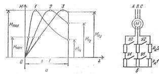
Rice. 1. Starting a three-phase asynchronous motor with a wound rotor: a - graphs of the dependence of the torque of a motor with a wound rotor on slip at various active resistances of resistors in the rotor circuit, b - diagram of the inclusion of resistors and closing acceleration contacts in the rotor circuit. Thus, with closed acceleration contacts U1, U2, i.e., when starting an asynchronous motor with short-circuited slip rings, the initial starting torque Mn1 = (0.5 -1.0) Mnom, and the initial starting current Iп = (4.5 - 7) Inom and more. Low initial starting torque asynchronous electric motor with a wound rotor may be insufficient to drive the production unit and its subsequent acceleration, and a significant starting current will cause increased heating of the motor windings, which limits the frequency of its switching on, and in low-power networks leads to a temporary voltage drop that is undesirable for the operation of other receivers. These circumstances may be the reason that precludes the use of asynchronous motors with a wound rotor with a large starting current to drive operating mechanisms. The introduction of adjustable resistors, called starting resistors, into the motor rotor circuit not only reduces the initial starting current, but at the same time increases the initial starting torque, which can reach the maximum torque Mmax (Fig. 1, a, curve 3), if the critical slip of the wound-rotor motor is skr = (R2" + Rd") / (X1 + X2") = 1, where Rd" is the active resistance of the resistor located in the phase of the motor rotor winding, reduced to the phase of the stator winding. A further increase in the active resistance of the starting resistor is impractical, since it leads to a weakening of the initial starting torque and the point of maximum torque entering the sliding region s > 1, which eliminates the possibility of acceleration of the rotor. Necessary active resistance resistors for starting a wound-rotor motor are determined based on the starting requirements, which can be easy when Mn = (0.1 - 0.4) Mn, normal if Mn - (0.5 - 0.75) Mn, and severe when Mn ≥ Mn. To maintain a sufficiently large torque by a wound-rotor motor during acceleration of a production unit in order to reduce the duration transition process and to reduce engine heating, it is necessary to gradually reduce the active resistance of the starting resistors. The permissible change in torque during acceleration M(t) is determined by electrical and mechanical conditions that limit the peak torque limit M > 0.85 Mmax, the switching moment M2 > > Ms (Fig. 2), as well as acceleration.

Rice. 2. Starting characteristics of a three-phase asynchronous motor with a wound rotor. Switching of starting resistors is ensured by alternately switching on the acceleration contactors Y1, Y2, respectively, at times t1, t2 counted from the moment the engine starts, when during acceleration the torque M becomes equal to the switching moment M2. Thanks to this, throughout the entire start-up, all peak moments are the same and all switching moments are equal to each other. Since the torque and current of an asynchronous motor with a wound rotor are mutually related, it is possible, when accelerating the rotor, to set the peak current limit I1 = (1.5 - 2.5) Inom and the switching current I2, which should ensure the switching moment M2 > Mc. Disconnecting asynchronous motors with a wound rotor from the supply network is always carried out with the rotor circuit short-circuited, in order to avoid the occurrence of overvoltages in the phases of the stator winding, which can exceed the rated voltage of these phases by 3 - 4 times if the rotor circuit is open at the moment the engine is turned off.
34 Frequency regulation. This method of speed control allows the use of the most reliable and cheapest asynchronous motors with a squirrel-cage rotor. However, to change the frequency of the supply voltage, a source of electric current of variable frequency is required. As the latter, either synchronous generators with variable frequency rotation, or frequency converters - electric machine or static, made on controlled semiconductor valves (thyristors). Currently, frequency converters have a rather complex circuit and a relatively high cost. However, the rapid development of power semiconductor technology allows us to hope for further improvement of frequency converters, which opens up prospects for the widespread use of frequency regulation. Detailed description of control laws for frequency regulation and analysis of the operation of an asynchronous motor when powered by a frequency converter are given in § 4.13 and 4.14. Regulation by changing the number of poles. This regulation allows you to obtain a stepwise change in the rotation speed. In Fig. 4.35 shown simplest scheme(for one phase), allowing you to double the number of poles of the stator winding. To do this, each phase of the stator winding is divided into two parts, which are switched from a series connection to a parallel one. From the figure it is clear that when coils 1-2 and 3-4 are connected into two parallel branches, the number of poles is halved, and therefore the frequency of rotation of the magnetic field is doubled. When switching, the number of turns connected in series in each phase is halved, but since the rotation speed doubles, the emf induced in the phase remains unchanged. Consequently, the motor can be connected to the network with the same voltage at both speeds. In order to avoid switching in the rotor winding, the latter is performed short-circuited. If you need to have three or four rotation frequencies, then another winding is placed on the stator, when switching it you can get two additional frequencies. Asynchronous motors with switching the number of poles are called multi-speed. Regulation by including a rheostat in the rotor circuit. When additional active resistances are connected to the rotor circuit R ext1, R ext2, R ext3 and others the form of dependence changes M = f(s) and mechanical characteristics n 2 = f(M) engine (Fig. 4.37, a). At the same time, a certain load moment M n match slip s 1 , s 2 , s 3 , ..., greater than slipping s e , when the engine operates at a natural characteristic (with R ext = 0). Consequently, the steady-state engine speed decreases from n e before P 1 P 2 , P 3 ,... (Fig. 4.37, b). This control method can only be used for wound-rotor motors. It allows you to smoothly change the rotation speed in within wide limits. Its disadvantages are: a) big losses energy in the control rheostat; b) excessively “soft” mechanical characteristics of the engine with high resistance in the rotor circuit. In some cases, the latter is unacceptable, since a small change in the load torque corresponds to a significant change in the rotation speed.
35 Asynchronous generator is an asynchronous electric machine (electric motor) operating in generator mode. With the help of a drive motor (in our case, a turbine engine), the rotor of an asynchronous electric generator rotates in the same direction as the magnetic field. In this case, the rotor slip becomes negative, a braking torque appears on the shaft of the asynchronous machine, and the generator transmits energy to the network. For excitement electromotive force its output circuit uses the residual magnetization of the rotor. Capacitors are used for this. Asynchronous generators are not susceptible to short circuits. An asynchronous generator is simpler than a synchronous one (for example car generator): if the latter has inductive coils placed on the rotor, then the rotor of an asynchronous generator is similar to a regular flywheel. Such a generator is better protected from dirt and moisture, and is more resistant to short circuit and overloads, and the output voltage of an asynchronous electric generator has a lower degree of nonlinear distortion. This allows the use of asynchronous generators not only to power industrial devices that are not critical to the shape of the input voltage, but also to connect electronic equipment. It is the asynchronous electric generator that is ideal source current for devices with active (ohmic) load: electric heaters, welding converters, incandescent lamps, electronic devices, computer and radio engineering. Advantages of an asynchronous generator. Such advantages include a low clearing factor (harmonic coefficient), which characterizes quantitative presence in the output voltage of the higher harmonic generator. Higher harmonics cause uneven rotation and unnecessary heating of electric motors. Synchronous generators can have a clearing factor of up to 15%, and the clearing factor of an asynchronous electric generator does not exceed 2%. Thus, an asynchronous electric generator produces almost only useful energy. Another advantage of an asynchronous electric generator is that it completely lacks rotating windings and electronic parts, which are sensitive to external influences and are quite often susceptible to damage. That's why asynchronous generator It is little subject to wear and can serve for a very long time. The output of our generators is immediately 220/380V AC, which can be used directly to household appliances (for example, heaters), to charge batteries, to connect to a sawmill, and also for parallel operation with a traditional network. In this case, you will pay the difference between what is consumed from the network and what is generated by the windmill. Because the voltage goes directly to industrial parameters, then you will not need various converters (inverters) when connecting the wind generator directly to your load. For example, you can directly connect to a sawmill and, in the presence of wind, work as if you had simply connected to a 380V network. As is known, to reduce braking time when stopping production machines and mechanisms, mechanical brakes are often used. Reducing braking time, especially in the case of a short operating cycle, leads to a significant increase in the productivity of machines and mechanisms. The disadvantages of mechanical brakes are the rapid wear of the rubbing surfaces, the complexity and need for periodic adjustment of the braking force, and the need for additional space to accommodate the brake and its connection to the mechanism. All of the listed disadvantages are eliminated if, for these purposes, instead of a mechanical brake, the properties of electric motors are used to operate in braking modes, i.e., essentially work as a generator and develop not a rotating, but a braking torque. In many lifting and transport machines (cranes, elevators, escalators, etc.), where movement under the influence of gravity is possible, a constant, steady speed of lowering loads is ensured using the braking torque of the electric motor. Electric motors direct current can operate in three braking modes:
In anti-switch mode;
In generator mode with energy output to the network;
In dynamic braking mode.
In any of the braking modes, the electric motor operates as a generator, converting, for example, the kinetic energy of moving parts or potential energy descending weight into electrical energy.
36 When reversing the engine while moving by switching the switch, the engine is first decelerated from a given speed to zero, and then accelerated in the other direction. Such braking can also be used for braking during the so-called anti-inclusion. With such reversing or braking, significant currents occur in an asynchronous motor with a squirrel-cage rotor. Therefore, based on the heating conditions for these engines, the number of reversals per hour is no more than tens. To limit currents and increase torques, a resistance is introduced into the phase rotor circuit of an asynchronous motor. Let's consider three main methods of electrical braking of asynchronous motors. Braking by counter-switching method, as stated, it is produced when the engine is switched on the fly. In this case, the magnetic field rotates in the opposite direction relative to the direction of rotation of the engine, and the torque of the engine is braking - it acts against the direction of rotation. Generator braking occurs when a multi-speed engine is switched on the go from a higher speed to a lower one, i.e. when switching a machine from a smaller number of poles to a larger one. At the first moment of switching, the engine speed turns out to be much greater than the speed of its field, i.e., the slip turns out to be negative and the machine switches to operating as a generator. Braking occurs with the conversion of the kinetic energy of rotating parts into electrical energy, which, minus losses in the machine, is sent to the network. Generator braking can also be used in a lift when lowering a heavy load, accelerating the engine to a speed exceeding synchronous speed; then the machine begins to release into the network the energy imparted to it by the descending load. Braking in generator operating mode is only possible at supersynchronous speed. If the engine must be stopped at the end of braking, then at the end of braking you should switch to mechanical braking or another type of electrical braking (dynamic, back-on). If necessary, the position at the end can only be secured using a mechanical brake. At dynamic braking The motor stator winding is disconnected from three-phase network and is connected to a direct or single-phase alternating current network. In this case, various ways of connecting the phases of the stator winding are possible. The stator winding, powered by direct current, creates a stationary magnetic field. Just as during normal operation of an engine its rotating field drags the rotor along with it, a stationary field during dynamic braking causes the rotor to quickly stop. Kinetic energy rotating parts turns into heat released in the rotor circuit due to currents induced in it by the stationary stator field. Smooth braking is ensured by regulating the voltage at the stator terminals. The braking torque of a motor with a wound rotor can also be regulated by a rheostat in the rotor circuit. The disadvantage of dynamic braking is that it requires a low voltage DC source.
37 Synchronous machine is an alternating current electric machine, the rotor speed of which is equal to the speed of rotation of the magnetic field in the air gap. The main parts of a synchronous machine are the armature and the inductor. The most common design is one in which the armature is located on the stator, and the inductor is located on the rotor separated from it by an air gap. The armature consists of one or more alternating current windings. In motors, currents injected into the armature create a rotating magnetic field, which meshes with the field of the inductor and thus energy conversion occurs. The armature field influences the inductor field and is therefore also called armature reaction field. In generators, the armature reaction field is created alternating currents induced in the armature winding from the inductor. The inductor consists of poles - direct current electromagnets or permanent magnets (in micromachines). Inductors synchronous machines have two various designs: salient-pole or non-salient-pole. A salient pole machine is distinguished by the fact that the poles are pronounced and have a design similar to the poles of a DC machine. With a non-salient-pole design, the excitation winding is placed in the grooves of the inductor core, very similar to the winding of the rotors of asynchronous machines with a wound rotor, with the only difference that between the poles there is a space left unfilled with conductors (the so-called big tooth). Non-salient pole designs are used in high-speed machines to reduce the mechanical load on the poles. To reduce magnetic resistance, that is, to improve the passage of magnetic flux, ferromagnetic cores of the rotor and stator are used. Basically, they are a laminated structure made of electrical steel (that is, assembled from separate sheets). Electrical steel has a number of interesting properties. Among other things, it has a high silicon content in order to increase its electrical resistance and thereby reduce eddy currents.
Electromagnetic rotating forces act on the rotor and stator poles.
moments that are equal in magnitude and directed in opposite directions.
The power required to rotate the stator poles at synchronous frequency is
where is the angular velocity.
The mechanical power developed by the rotor is

Where  - angular speed of the rotor.
Power difference
where R E2 - electrical losses in the rotor winding;
m 2 - number of phases of the rotor winding;
R 2 - active resistance of the rotor winding;
I 2 - rotor current.
where 
Torque:
 (12.4).
where CT is the transformation ratio of an engine with a locked rotor,
 - constant.
In Fig. Figure 12.5 shows the dependence of the electromagnetic torque on slip in the form of a solid line.

Let the actuator driven by this engine create a counteracting braking torque M2.
In Fig. 12.5 there are two points for which the equality is true M em = M 2
;
these are the dots A
And V
.
At the point A
the engine runs stably. If the engine, under the influence of any reason, reduces the rotation speed, then its slip will increase, and along with it the torque will increase. Thanks to this, the engine speed will increase and balance will be restored again. M em = M 2
;.
At the point V
engine operation cannot be stable: random deviation rotation speed will either stop the engine or cause it to reach a point A
.
Consequently, the entire ascending branch of the characteristic is the region stable operation engine, and the entire downstream part is an area of unstable operation. Dot b
, corresponding to the maximum torque, separates the areas of stable and unstable operation.
The maximum torque value corresponds to the critical slip S k
. Slipping S=1
corresponds to the starting torque. If the magnitude of the counteracting braking torque M 2
more than the starting MP, the engine will not start when turned on and will remain motionless.
The mechanical characteristic of an asynchronous motor is the dependence of the motor speed on the torque on the shaft n 2 = f (M 2). The mechanical characteristic is obtained under the condition U 1 - const, f 1 - const. The mechanical characteristic of the engine is the dependence of torque on slip, plotted on a different scale. In Fig. Figure 12.6 shows a typical mechanical characteristic of an asynchronous motor.
With increasing load, the torque on the shaft increases to a certain maximum value, and the rotation speed decreases. As a rule, an asynchronous motor has a starting torque less than the maximum. This is explained by the fact that in the starting mode, when n 2 = 0 and S = 1, the asynchronous motor is in a mode similar to a short circuit in a transformer. The magnetic field of the rotor is directed opposite to the magnetic field of the stator.
The resulting, or main, magnetic flux in the air gap of the machine in starting mode, as well as the emf in the stator and rotor E 1 and E 2, are significantly reduced. This leads to a decrease in the starting torque of the engine and a sharp increase in the starting current.
12.4. Regulating the rotation speed of asynchronous motors.
Reversing an asynchronous motor
From formula (12.2) we obtain
 . (12.11)
From formula (12.11) it is clear that the rotation speed of an asynchronous motor can be changed in three ways:
1. changing the frequency of the supply voltage;
2. changing the number of motor poles. To do this, a winding is placed in the stator slots, which can be switched to a different number of poles;
3. change in slip. This method can be used in asynchronous motors with a wound rotor. To do this, an adjusting rheostat is included in the rotor circuit. An increase in the active resistance of the rotor circuit leads to an increase in slip from S a to S g (see Fig. 12.5), and, consequently, to a decrease in engine speed.
Asynchronous motors have simple design and reliable in operation. The disadvantage of asynchronous motors is the difficulty of regulating their rotation speed.
To reverse a three-phase asynchronous motor (change the direction of rotation of the motor to the opposite), it is necessary to swap two phases, that is, swap any two linear wires suitable for the stator winding of the motor.
The voltage U 1 applied to the stator winding phase is balanced by the main emf E 1 , the leakage emf and the voltage drop across the active resistance of the stator winding:
In a rotor winding, a similar equation will look like:
But since the rotor winding is closed, the voltage U 2 =0, and if we also take into account that E 2s = SE 2 and x 2s = Sx 2, then the equation can be rewritten as:
![]()
The current equation for an asynchronous motor repeats a similar equation for a transformer:
28 Torque of asynchronous motor
The torque in an asynchronous motor is created by the interaction of the rotor current with the magnetic field of the machine. Torque can be expressed mathematically in terms of the electromagnetic power of the machine:
Where w 1 =2pn 1 /60 - angular frequency of field rotation. In its turn, n 1 =f 1 60/R, Then
![]()
Let's substitute into the formula M 1 expression REm=Pe2/S and dividing by 9.81, we get:
![]()
Induction Motor Torque Equation
It follows that the motor torque is proportional to the electrical losses in the rotor. Let's substitute the current value into the last formula I 2 ’ :
we obtain the equation for the torque of an asynchronous motor:
Where U 1 - phase voltage of the stator winding.
29 .Mechanical characteristics of the engine is called the dependence of the rotor speed on the torque on the shaft n = f (M2). Since the no-load torque is small under load, M2 ≈ M and the mechanical characteristic is represented by the dependence n = f (M). If we take into account the relationship s = (n1 - n) / n1, then the mechanical characteristic can be obtained by presenting its graphical dependence in coordinates n and M (Fig. 1).
Rice. 1. Mechanical characteristics of an asynchronous motor
Natural mechanical characteristic of an induction motor corresponds to the main (certificate) circuit of its connection and the nominal parameters of the supply voltage. Artificial characteristics are obtained if any additional elements are included: resistors, reactors, capacitors. When the motor is powered with a non-rated voltage, the characteristics also differ from the natural mechanical characteristics.
Mechanical characteristics are a very convenient and useful tool for analyzing the static and dynamic modes of an electric drive.
30 Mechanical characteristics and self-regulation of the engine. The graph connecting mechanical quantities - speed and torque - is called the mechanical characteristic of an asynchronous motor (Fig. 7) n = ƒ(M). Self-regulation of an asynchronous motor is as follows. Let the engine operate stably in some mode, developing speed n1 and torque M1. With uniform rotation, this torque is equal to the braking torque M t1, i.e. M1=M T 1, n1= conset. An increase in braking torque to M2 will cause a decrease in machine speed, since the braking torque will become greater than the torque. As the speed decreases, the slip increases, which in turn causes an increase in the emf and current in the rotor. This increases engine torque. This process ends when the torque M2 developed by the engine becomes equal to M T 2. In this case, the rotation speed is set lower than n1. The property of automatically establishing a balance between braking and torque is called self-regulation.
On a laboratory bench, the engine is loaded with an electric brake, consisting of an electromagnet, in the gap of which a disk mounted on the engine shaft rotates. By changing the voltage supplying the electromagnet coil with the handle of the autotransformer, you can change the braking force, the moment of which is equal to: M BRAKE = F r (N m)
where F is the force (force) acting on the pulley circumference, (N);
r is the radius of the pulley, equal to 0.18 m. Net power on the motor shaft:
Where n- engine rotation speed, rpm.
where ƒ is the network frequency (equal to 50 Hz),
R- number of pairs of poles of the stator winding (equal to 2).
n 1 - synchronous speed of the rotating magnetic field.
The engine rotation speed is determined using a tachometer. Slip is calculated using the formula:
31 Performance characteristics are called the dependences of the power consumed by the engine, current consumption I, power factor, engine rotation speed, efficiency and torque M on the useful engine power delivered to the shaft. Performance characteristics determine the basic operational properties of an asynchronous motor. The performance characteristics of a medium power asynchronous motor are shown in Fig. 8.8. Their behavior is explained as follows. At light loads, the current consumed by the motor I (no-load current) can range from 20 to 70% of the rated current. As the load increases, the current in the rotor circuit increases, which leads to an almost proportional increase in current I in the stator circuit.
Fig.8.8 Motor torque () is also almost proportional to the load, but at high loads the linearity of the graph is somewhat disrupted due to a decrease in the engine rotation speed. The performance characteristic expresses the relationship between the power developed by the motor and the phase shift between the stator current and voltage. An asynchronous motor, like a transformer, consumes current I from the network, which is significantly out of phase with the applied voltage. For example, in idle mode. As the load on the motor shaft increases, the active components of the rotor and stator currents increase, increasing . The maximum value is reached at .
With further increase, the value will decrease slightly. This is explained by an increase in slip s, which causes an increase in the reactance of the rotor winding, and consequently, the phase shift . WITH increases and, i.e. will decrease.
The behavior of the operating characteristic is explained as follows. The efficiency value is determined by the ratio of useful power to power consumed from the network.
The quantity is called power loss. In addition to losses in the stator and rotor steel due to magnetization reversal and eddy currents, which together with mechanical losses can be considered constant, in an asynchronous motor there are losses in copper ,
those. in the stator and rotor windings, which are proportional to the square of the flowing current and, therefore, depend on the load. During no-load operation, as in a transformer, losses in steel predominate, since a is equal to the no-load current, which is small. At small loads on the shaft, the losses in copper still remain small, and therefore the efficiency, determined by the formula ![]() (8.5)
(8.5)
with increase, it first increases sharply. When constant losses become equal to load-dependent losses , efficiency reaches its maximum value. With a further increase in load, variable power losses increase significantly, resulting in efficiency. decreases noticeably. Nature of addiction ) can be explained from the relation . If the efficiency was constant, then there would be a linear relationship between and. But since the efficiency depends on and this dependence initially increases sharply, and with a further increase in load changes insignificantly, then the curve ) At first it grows slowly and then increases sharply.
32 In any electrical circuit, the sum of the powers of all sources of electrical energy must be equal to the sum of the powers of all receivers and auxiliary elements. Having previously obtained the power expressions, we can write in general form the power balance equation for any electrical circuit:
Σ E → I → + Σ U ← I → = Σ E ← I → + Σ U → I → + Σ I 2 r.
Equation (1.35) can be written both for the actual directions of the emf, voltages and currents, and for the case when some of them are arbitrarily chosen positive directions. In the first case, all terms in it will be positive and the corresponding elements of the circuit will actually be sources or receivers of electrical energy. If some terms are written taking into account arbitrarily chosen positive directions, the corresponding elements must be considered as putative sources and receivers. As a result of calculation or analysis, some of them may turn out to be negative. This will mean that some of the supposed sources are actually a receiver, and some of the supposed receivers are actually a source.
33 Starting an asynchronous motor is accompanied by a transient process of the machine associated with the transition of the rotor from a state of rest to a state of uniform rotation, in which the engine torque balances the moment of resistance forces on the machine shaft. When starting an asynchronous motor, there is an increased consumption of electrical energy from the supply network, which is spent not only on overcoming the braking torque applied to the shaft and covering losses in the asynchronous motor itself, but also on imparting a certain kinetic energy to the moving parts of the production unit. Therefore, when starting, an asynchronous motor must develop increased torque. For asynchronous motor with wound rotor the initial starting torque corresponding to slip sp = 1 depends on the active resistance of the adjustable resistors introduced into the rotor circuit.
Rice. 1. Starting a three-phase asynchronous motor with a wound rotor: a - graphs of the dependence of the torque of a motor with a wound rotor on slip at various active resistances of resistors in the rotor circuit, b - diagram of the inclusion of resistors and closing acceleration contacts in the rotor circuit. Thus, with closed acceleration contacts U1, U2, i.e., when starting an asynchronous motor with short-circuited slip rings, the initial starting torque Mn1 = (0.5 -1.0) Mnom, and the initial starting current Iп = (4.5 - 7) Inom and more. A small initial starting torque of an asynchronous electric motor with a wound rotor may be insufficient to drive a production unit and its subsequent acceleration, and a significant starting current will cause increased heating of the motor windings, which limits the frequency of its switching on, and in low-power networks leads to undesirable operation of other receivers temporary voltage drop. These circumstances may be the reason that precludes the use of asynchronous motors with a wound rotor with a large starting current to drive operating mechanisms. The introduction of adjustable resistors, called starting resistors, into the motor rotor circuit not only reduces the initial starting current, but at the same time increases the initial starting torque, which can reach the maximum torque Mmax (Fig. 1, a, curve 3), if the critical slip of the wound-rotor motor is skr = (R2" + Rd") / (X1 + X2") = 1, where Rd" is the active resistance of the resistor located in the phase of the motor rotor winding, reduced to the phase of the stator winding. A further increase in the active resistance of the starting resistor is impractical, since it leads to a weakening of the initial starting torque and the point of maximum torque entering the sliding region s > 1, which eliminates the possibility of acceleration of the rotor. The required active resistance of resistors for starting a wound-rotor motor is determined based on the starting requirements, which can be easy when Mn = (0.1 - 0.4) Mnom, normal if Mn - (0.5 - 0.75) Mn, and heavy when Mn ≥ Mn. To maintain a sufficiently large torque by a wound-rotor motor during acceleration of a production unit in order to shorten the duration of the transient process and reduce engine heating, it is necessary to gradually reduce the active resistance of the starting resistors. The permissible change in torque during acceleration M(t) is determined by electrical and mechanical conditions that limit the peak torque limit M > 0.85 Mmax, switching moment M2 > > Ms (Fig. 2), as well as acceleration.
Rice. 2. Starting characteristics of a three-phase asynchronous motor with a wound rotor. Switching of starting resistors is ensured by alternately switching on the acceleration contactors Y1, Y2, respectively, at times t1, t2 counted from the moment the engine starts, when during acceleration the torque M becomes equal to the switching moment M2. Thanks to this, throughout the entire start-up, all peak moments are the same and all switching moments are equal to each other. Since the torque and current of an asynchronous motor with a wound rotor are mutually related, it is possible, when accelerating the rotor, to set the peak current limit I1 = (1.5 - 2.5) Inom and the switching current I2, which should ensure the switching moment M2 > Mc. Disconnecting asynchronous motors with a wound rotor from the supply network is always carried out with the rotor circuit short-circuited, in order to avoid the occurrence of overvoltages in the phases of the stator winding, which can exceed the rated voltage of these phases by 3 - 4 times if the rotor circuit is open at the moment the engine is turned off.
34 Frequency regulation. This method of speed control allows the use of the most reliable and cheapest asynchronous motors with a squirrel-cage rotor. However, to change the frequency of the supply voltage, a source of electric current of variable frequency is required. As the latter, either synchronous generators with variable speed are used, or frequency converters - electric machine or static, made on controlled semiconductor valves (thyristors). Currently, frequency converters have a rather complex circuit and a relatively high cost. However, the rapid development of power semiconductor technology allows us to hope for further improvement of frequency converters, which opens up prospects for the widespread use of frequency regulation. A detailed description of the control laws for frequency regulation and an analysis of the operation of an asynchronous motor when powered by a frequency converter are given in § 4.13 and 4.14. Regulation by changing the number of poles. This regulation allows you to obtain a stepwise change in the rotation speed. In Fig. Figure 4.35 shows the simplest circuit (for one phase), which allows you to double the number of poles of the stator winding. To do this, each phase of the stator winding is divided into two parts, which are switched from a series connection to a parallel one. From the figure it is clear that when coils 1-2 and 3-4 are connected into two parallel branches, the number of poles is halved, and therefore the frequency of rotation of the magnetic field is doubled. When switching, the number of turns connected in series in each phase is halved, but since the rotation speed doubles, the emf induced in the phase remains unchanged. Consequently, the motor can be connected to the network with the same voltage at both speeds. In order to avoid switching in the rotor winding, the latter is performed short-circuited. If you need to have three or four rotation frequencies, then another winding is placed on the stator, when switching it you can get two additional frequencies. Asynchronous motors with switching the number of poles are called multi-speed. Regulation by including a rheostat in the rotor circuit. When additional active resistances are connected to the rotor circuit R ext1, R ext2, R ext3 and others the form of dependence changes M = f(s) and mechanical characteristics n 2 = f(M) engine (Fig. 4.37, a). At the same time, a certain load moment M n match slip s 1 , s 2 , s 3 , ..., greater than slipping s e , when the engine operates at a natural characteristic (with R ext = 0). Consequently, the steady-state engine speed decreases from n e before P 1 P 2 , P 3 ,... (Fig. 4.37, b). This control method can only be used for wound-rotor motors. It allows you to smoothly change the rotation speed over a wide range. Its disadvantages are: a) large energy losses in the control rheostat; b) excessively “soft” mechanical characteristics of the engine with high resistance in the rotor circuit. In some cases, the latter is unacceptable, since a small change in the load torque corresponds to a significant change in the rotation speed.
35 Asynchronous generator is an asynchronous electric machine (electric motor) operating in generator mode. With the help of a drive motor (in our case, a turbine engine), the rotor of an asynchronous electric generator rotates in the same direction as the magnetic field. In this case, the rotor slip becomes negative, a braking torque appears on the shaft of the asynchronous machine, and the generator transmits energy to the network. To excite the electromotive force in its output circuit, the residual magnetization of the rotor is used. Capacitors are used for this. Asynchronous generators are not susceptible to short circuits. An asynchronous generator is designed simpler than a synchronous generator (for example, a car generator): if the latter has inductance coils placed on its rotor, then the rotor of an asynchronous generator is similar to a regular flywheel. Such a generator is better protected from dirt and moisture, more resistant to short circuits and overloads, and the output voltage of an asynchronous electric generator has a lower degree of nonlinear distortion. This allows the use of asynchronous generators not only to power industrial devices that are not critical to the shape of the input voltage, but also to connect electronic equipment. It is the asynchronous electric generator that is the ideal current source for devices with active (ohmic) loads: electric heaters, welding converters, incandescent lamps, electronic devices, computer and radio equipment. Advantages of an asynchronous generator . Such advantages include a low clearing factor (harmonic factor), which characterizes the quantitative presence of higher harmonics in the output voltage of the generator. Higher harmonics cause uneven rotation and unnecessary heating of electric motors. Synchronous generators can have a clearing factor of up to 15%, and the clearing factor of an asynchronous electric generator does not exceed 2%. Thus, an asynchronous electric generator produces almost only useful energy. Another advantage of an asynchronous electric generator is that it completely lacks rotating windings and electronic parts, which are sensitive to external influences and are quite often susceptible to damage. Therefore, the asynchronous generator is subject to little wear and tear and can serve for a very long time. The output of our generators is immediately 220/380V AC, which can be used directly to household appliances (for example, heaters), to charge batteries, to connect to a sawmill, and also for parallel operation with a traditional network. In this case, you will pay the difference between what is consumed from the network and what is generated by the windmill. Because the voltage goes directly to industrial parameters, then you will not need various converters (inverters) when connecting the wind generator directly to your load. For example, you can directly connect to a sawmill and, in the presence of wind, work as if you had simply connected to a 380V network. As is known, to reduce braking time when stopping production machines and mechanisms, mechanical brakes are often used. Reducing braking time, especially in the case of a short operating cycle, leads to a significant increase in the productivity of machines and mechanisms. The disadvantages of mechanical brakes are the rapid wear of the rubbing surfaces, the complexity and need for periodic adjustment of the braking force, and the need for additional space to accommodate the brake and its connection to the mechanism. All of the listed disadvantages are eliminated if, for these purposes, instead of a mechanical brake, the properties of electric motors are used to operate in braking modes, i.e., essentially work as a generator and develop not a rotating, but a braking torque. In many lifting and transport machines (cranes, elevators, escalators, etc.), where movement under the influence of gravity is possible, a constant, steady speed of lowering loads is ensured using the braking torque of the electric motor. DC motors can operate in three braking modes:
In anti-switch mode;
In generator mode with energy output to the network;
In dynamic braking mode.
In any of the braking modes, the electric motor operates as a generator, converting, for example, the kinetic energy of moving parts or the potential energy of a lowering load into electrical energy.
36 When reversing the engine while moving by switching the switch, the engine is first decelerated from a given speed to zero, and then accelerated in the other direction. Such braking can also be used for braking during the so-called anti-inclusion. With such reversing or braking, significant currents occur in an asynchronous motor with a squirrel-cage rotor. Therefore, based on the heating conditions for these engines, the number of reversals per hour is no more than tens. To limit currents and increase torques, a resistance is introduced into the phase rotor circuit of an asynchronous motor. Let's consider three main methods of electrical braking of asynchronous motors. Braking by counter-switching method, as stated, it is produced when the engine is switched on the fly. In this case, the magnetic field rotates in the opposite direction relative to the direction of rotation of the engine, and the torque of the engine is braking - it acts against the direction of rotation. Generator braking occurs when a multi-speed engine is switched on the go from a higher speed to a lower one, i.e. when switching a machine from a smaller number of poles to a larger one. At the first moment of switching, the engine speed turns out to be much greater than the speed of its field, i.e., the slip turns out to be negative and the machine switches to operating as a generator. Braking occurs with the conversion of the kinetic energy of rotating parts into electrical energy, which, minus losses in the machine, is transmitted to the network. Generator braking can also be used in a lift when lowering a heavy load, accelerating the engine to a speed exceeding synchronous speed; then the machine begins to release into the network the energy imparted to it by the descending load. Braking in generator operating mode is only possible at supersynchronous speed. If the engine must be stopped at the end of braking, then at the end of braking you should switch to mechanical braking or another type of electrical braking (dynamic, back-on). If necessary, the position at the end can only be secured using a mechanical brake. At dynamic braking The stator winding of the motor is disconnected from the three-phase network and connected to the DC or single-phase alternating current network. In this case, various ways of connecting the phases of the stator winding are possible. The stator winding, powered by direct current, creates a stationary magnetic field. Just as during normal operation of an engine its rotating field drags the rotor along with it, a stationary field during dynamic braking causes the rotor to quickly stop. The kinetic energy of the rotating parts turns into heat, released in the rotor circuit due to the currents induced in it by the stationary stator field. Smooth braking is ensured by regulating the voltage at the stator terminals. The braking torque of a motor with a wound rotor can also be regulated by a rheostat in the rotor circuit. The disadvantage of dynamic braking is that it requires a low voltage DC source.
37 Synchronous machine is an alternating current electric machine, the rotor speed of which is equal to the speed of rotation of the magnetic field in the air gap. The main parts of a synchronous machine are the armature and the inductor. The most common design is one in which the armature is located on the stator, and the inductor is located on the rotor separated from it by an air gap. The armature consists of one or more alternating current windings. In motors, currents injected into the armature create a rotating magnetic field, which meshes with the field of the inductor and thus energy conversion occurs. The armature field influences the inductor field and is therefore also called armature reaction field. In generators, the armature reaction field is created by alternating currents induced in the armature winding from an inductor. The inductor consists of poles - direct current electromagnets or permanent magnets (in micromachines). Synchronous machine inductors have two different designs: salient-pole or non-salient-pole. A salient pole machine is distinguished by the fact that the poles are pronounced and have a design similar to the poles of a DC machine. With a non-salient-pole design, the excitation winding is placed in the grooves of the inductor core, very similar to the winding of the rotors of asynchronous machines with a wound rotor, with the only difference that between the poles there is a space left unfilled with conductors (the so-called big tooth). Non-salient pole designs are used in high-speed machines to reduce the mechanical load on the poles. To reduce magnetic resistance, that is, to improve the passage of magnetic flux, ferromagnetic cores of the rotor and stator are used. Basically, they are a laminated structure made of electrical steel (that is, assembled from separate sheets). Electrical steel has a number of interesting properties. Among other things, it has a high silicon content in order to increase its electrical resistance and thereby reduce eddy currents.
 (1 ratings, on average: 5,00 out of 5)

