Manufacturing of reels to order. Winding coils and chokes. Manufacturing of individual parts
Clone PI-W and, now, it came to making a mono search coil. And since I am currently experiencing some financial difficulties, I was faced with not an easy task- make the reel yourself from the cheapest materials possible.
Looking ahead, I’ll say right away that I coped with the task. As a result, I got this sensor:
By the way, the resulting ring coil is perfect not only for Clone, but also for almost any other impulse generator (Koschei, Tracker, Pirate).
I will tell you in great detail, since the devil is often in the details. Moreover, short stories making coils is a dime a dozen on the Internet (like, we take this, then we cut it off, wrap it, glue it together and you’re done!) But you start doing it yourself and it turns out that the most important thing was mentioned in passing, and something else was completely forgotten to be said... And it turns out that that everything is more complicated than it seemed at the very beginning.
This won't happen here. Ready? Go!
Idea
Easiest for self-made I thought this design: take a disk from sheet material thickness ~4-6 mm. The diameter of this disk is determined by the diameter of the future winding (in my case it should be 21 cm).
Then we glue two disks of slightly larger diameter to this pancake on both sides to make a bobbin for winding wire. Those. such a coil greatly increased in diameter, but flattened in height.
For clarity, I’ll try to depict this in a drawing: 
I hope the main idea is clear. Just three disks glued together over the entire area.
Material selection
I planned to use plexiglass as the material. It is perfectly processed and glued with dichloroethane. But, unfortunately, I couldn’t find it for free.
All sorts of collective farm materials such as plywood, cardboard, bucket lids, etc. I immediately discarded them as unsuitable. I wanted something strong, durable and preferably waterproof.
And then my gaze turned to fiberglass...
It's no secret that fiberglass (or glass mat, fiberglass) can be used to make whatever your heart desires. Even motor boats and car bumpers. The fabric is impregnated epoxy resin, give her the required form and leave until completely hardened. The result is a durable, water-resistant, easy-to-handle material. And this is exactly what we need.
So, we need to make three pancakes and ears for attaching the barbell.
Manufacturing of individual parts
Pancakes No. 1 and No. 2
Calculations showed that to obtain a sheet 5.5 mm thick, you need to take 18 layers of fiberglass. To reduce epoxy consumption, it is better to pre-cut the fiberglass into circles of the required diameter.
For a disk with a diameter of 21 cm, 100 ml of epoxy resin was just enough.
Each layer must be thoroughly coated, and then the entire stack must be placed under the press. The greater the pressure, the better - the excess resin will be squeezed out, the mass of the final product will become a little less, and the strength will be a little greater. I loaded about a hundred kilograms on top and left it until the morning. The next day I ended up with this pancake: 
This is the most massive part of the future coil. He weighs - be healthy! 
Then I’ll tell you how using this spare part it will be possible to significantly reduce the weight of the finished sensor.
A disk with a diameter of 23 cm and a thickness of 1.5 mm was made in exactly the same way. Its weight is 89 g.
Pancake #3
There was no need to glue the third disk. I had a sheet of fiberglass at my disposal. suitable size and thickness. It was printed circuit board from some ancient device: 
Unfortunately, the fee was with metallized holes, so I had to spend some time drilling them out.
I decided that this would be the top disk, so I made a hole in it for the cable entry. 
Ears for barbell
There was just enough leftover textolite for the ears to attach the sensor housing to the rod. I cut out two pieces for each ear (to make it durable!) 
You should immediately drill holes in your ears for the plastic bolt, as it will be very inconvenient to do this later. 
By the way, this is a mounting bolt for the toilet seat.
So, all the components of our coil are ready. All that remains is to glue it all together into one big sandwich. And don't forget to run the cable inside.
Assembly into one piece
First, the upper disk made of holey fiberglass was glued to the middle pancake made of 18 layers of fiberglass. This took literally a few milliliters of epoxy - this was enough to coat both surfaces to be glued over the entire area. 


Ear mounting
I cut the grooves using a jigsaw. Naturally, I overdid it a little in one place: 
To make the ears fit well, I made a small bevel on the edges of the cuts: 
Now we had to decide which option is better? Ears can be placed in different ways... 
Reels industrial production Most often they are made according to the right version, but I like the left one better. In general, I often make leftist decisions...
In theory, the right method is better balanced, because The rod mount is closer to the center of gravity. But it is far from a fact that after lightening the coil, its center of gravity will not shift in one direction or another.
The left mounting method looks more visually pleasing (IMHO), and in this case total length The folded metal detector will be a couple of centimeters smaller. For someone who plans to carry the device in a backpack, this may be important.
In general, I made my choice and started gluing. He generously smeared it with bauxite, securely fixed it in the desired position and left it to harden: 
After hardening, I sanded off everything sticking out from the back side with sandpaper: 

Cable entry
Then, using a round file, I prepared grooves for the conductors, inserted the connecting cable through the hole and glued it tightly: 

To prevent strong kinks, the cable at the entry point needed to be somehow reinforced. For these purposes, I used this little rubber thing that I got from God knows where: 
In short, I cut some fiberglass: 
and mixed it thoroughly with bauxite with the addition of ballpoint pen paste. The result was a viscous substance similar to wet hair. With this composition you can cover any cracks without problems: 
Pieces of fiberglass give the putty the necessary viscosity, and after hardening they provide increased strength glue seam.
So that the mixture is properly compacted, and the resin saturates the turns of the wire, I wrap it all with electrical tape tightly: 
The electrical tape must be green or, at worst, blue.
After everything froze thoroughly, I wondered how strong the structure turned out to be. It turned out that the reel could easily support my weight (about 80 kg).
In fact, we don’t need such a heavy-duty reel; its weight is much more important. Too much mass of the sensor will definitely cause shoulder pain, especially if you plan to conduct a long search.
Facilitating
To reduce the weight of the coil, it was decided to cut out some sections of the structure: 
This manipulation allowed me to lose 168 grams excess weight. At the same time, the strength of the sensor has practically not decreased, as can be seen in this video:
Now, with hindsight, I understand how the coil could have been made a little lighter. To do this, it was necessary to make large holes in the middle pancake in advance (before gluing everything together). Something like this: 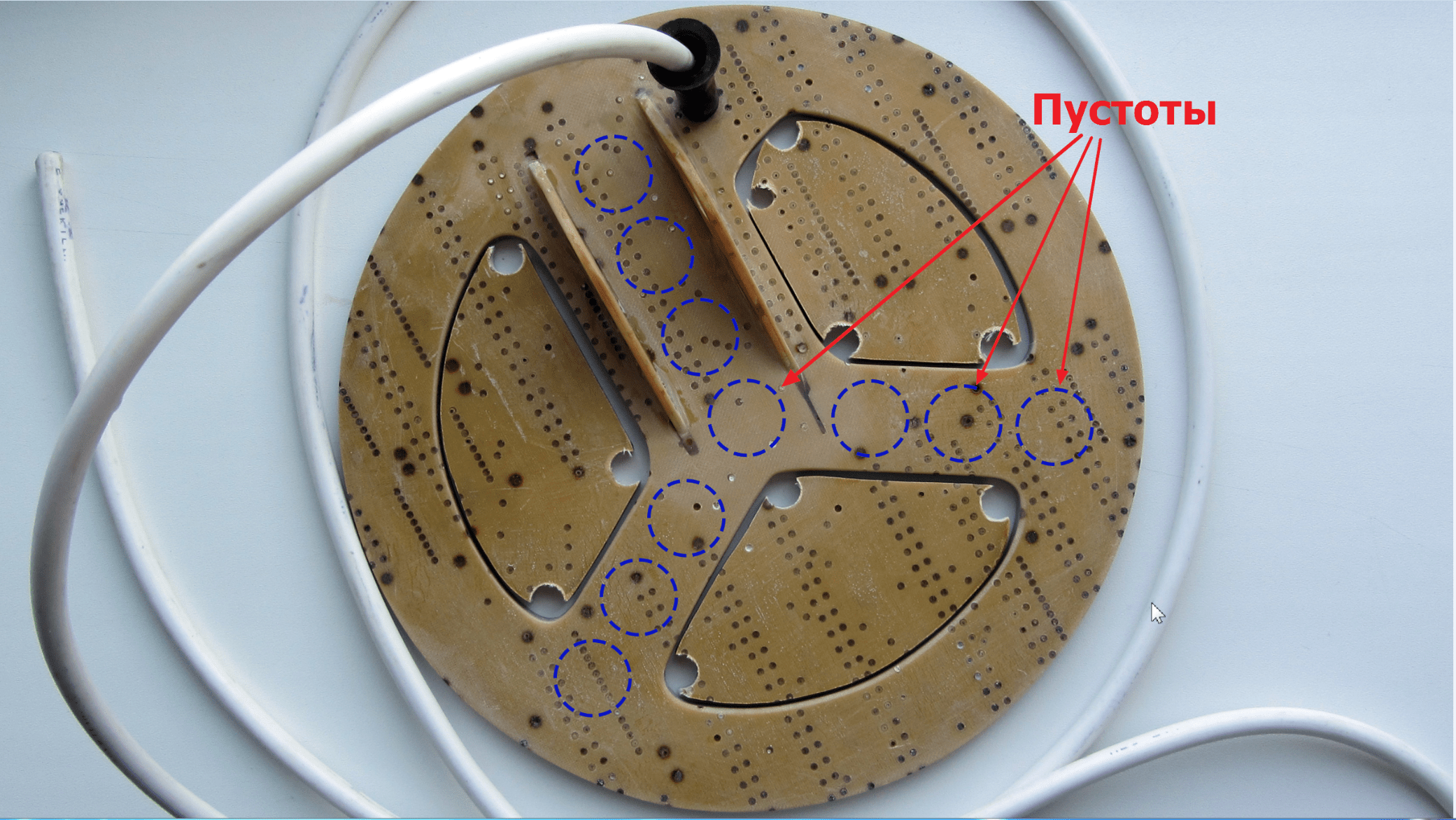
The voids inside the structure would have almost no effect on the strength, but would reduce the total mass by another 20-30 grams. Now, of course, it’s too late to rush around, but I’ll keep it in mind for the future.
Another way to simplify the design of the sensor is to reduce the width of the outer ring (where the wire turns are laid) by 6-7 millimeters. Of course, this can be done now, but there is no such need yet.
Finish painting
Found excellent paint for fiberglass laminate and fiberglass products - epoxy resin with the addition of a dye of the desired color. Since the entire structure of my sensor is made on the basis of bauxite, the resin-based paint will have excellent adhesion and will fit like original.
I used alkyd enamel PF-115 as a black dye, adding it until the required hiding power was obtained.
As practice has shown, a layer of such paint holds very firmly, and looks as if the product was dipped in liquid plastic: 

In this case, the color can be any depending on the enamel used.
Final weight search coil together with the cable after painting - 407 g 
The cable separately weighs ~80 grams.
Examination
After our homemade reel was completely ready for the metal detector, it was necessary to check it for the absence of an internal break. The easiest way to check is to use a tester to measure the winding resistance, which normally should be very low (maximum 2.5 Ohms).
In my case, the resistance of the coil together with two meters of connecting cable turned out to be around 0.9 Ohm.
Unfortunately, this in a simple way It will not be possible to detect an interturn short circuit, so you have to rely on your accuracy when winding. A short circuit, if there is one, will immediately manifest itself after starting the circuit - the metal detector will consume increased current and have extremely low sensitivity.
Conclusion
So, I think that the task was completed successfully: I managed to make a very durable, waterproof and not too heavy reel from the most waste materials. List of expenses:
- Fiberglass sheet 27 x 25 cm - free;
- Sheet of fiberglass, 2 x 0.7 m - free;
- Epoxy resin, 200 g - 120 rubles;
- Enamel PF-115, black, 0.4 kg - 72 RUR;
- Winding wire PETV-2 0.71 mm, 100 g - 250 rub;
- Connecting cable PVS 2x1.5 (2 meters) - 46 rubles;
- Cable entry is free.
Now I am faced with the task of making exactly the same rogue barbell. But that's already it.

The Tochnost enterprise produces high-precision coils, as well as other winding products with a wire diameter of 0.01-0.5 mm and an outer winding diameter of up to 450 mm. Such elements are used in the radio engineering and electronics industries.
The technical equipment of the production allows you to maintain a given number of turns with precision up to the turn and quickly produce products in large and small batches.
Winding coils to order is possible if the design documentation is available: electrical diagram, assembly drawing or product sketch.
Winding machines "Meteor"
To work with winding products, high-tech Swiss Meteor machines are used: they meet all the necessary requirements for equipment of this type.
The METEOR winding machine has the following characteristics:
- It is capable of winding custom coils with an accuracy of +1 turn;
- Suitable for ordinary, sectional and other types of winding;
- The total number of turns reaches 15,000;
- Winding width ranges from 0.2 to 70 millimeters;
- The wire diameter is 0.01-0.5 mm;
- Outside diameter windings fluctuates within 50 mm.
The built-in drive allows you to adjust the winding mode depending on the type of product and easily reprogram it to the required parameters. The design of the machine is designed to ensure maximum winding accuracy and operational stability. High productivity ensures prompt order fulfillment, regardless of the batch size, as well as reduced cost of the final product.
All this allows customers of Tochnost LLC to receive all the benefits of the company’s flexible pricing policy.
LLC "Accuracy" is modern production radio engineering coils and winding products for watches, electronics and complex industrial equipment. Our high professionalism and many years of experience are a guarantee that you will like the result of our cooperation!
You can get specialist advice or leave a request by phone
Sergey Komarov, UA3ALW
To perform Universal winding, you need an enameled winding wire in silk or lavsan insulation of the types PELSHO, PESHO, LESHO, PELO, LELO. Additional fibrous insulation performs two functions: it prevents the wire from sliding off the frame and from each other with obliquely located turns, and allows subsequent impregnation with polystyrene varnish, paraffin or ceresin to rigidly fix the arrangement of turns of the multilayer coil, which ensures high stability of its inductance.
With some skill, winding can be easily done by hand. To do this, you need to mark the frame itself, as shown in Figure 1, or wrap it in cable paper with markings applied to it. At the winding site, two circular lines are drawn, the distance between which will determine the width of the winding. Next, draw two diametrically opposite lines AB and CD. The distance between them should be exactly equal to half a turn. If you plan to wind several sections or inductively coupled coils on the frame, then markings are made for all windings at once. Markings should be made with non-conductive electricity dye (a simple pencil is not suitable, since its lead is made of graphite).
Next, using tape outside the markings, we secure the wire at the beginning of winding so that it passes through point A, and with a slight tension, we lay it diagonally along half a circle from point A to point D. At point D we bend the wire at an obtuse angle and, holding it nail angle thumb(for girls and young wives this is especially good), with less tension, we lay the wire obliquely in the opposite direction to point A. Having arrived at point A, we cross the wire of the beginning, pressing it with a new turn, and immediately bend it at an obtuse angle, but now already in the opposite direction and begin to lay the second turn close to the first, to the right of it. At the same time, again, use your thumbnail to hold the bend angle of the wire from sliding towards the center of the winding. Once you have acquired the skill, you can do this with the wire of the next turn, first bending it a little in outside(to tighten the angle of the previous turn) and only then, pressing it with a fingernail, at an obtuse angle, inward, and laying it parallel to the previous turn.
During the winding process, with each bend in the wire, it is necessary to tighten the bend angle to the ring marking line. Since the turns of the winding are arranged obliquely, and when the wire is tensioned, the winding tends to narrow, winding is carried out with a slight tension. To obtain an even section of the winding, it is necessary to place all the bend angles of the wire exactly on the line of the ring markings, and make the bend sharp, holding the wire with the nail of the thumb of your left hand.
Before you start winding Universal coils with a thin winding wire, you should practice performing such cross winding, for example, on the mounting wire MGShV-0.2, winding it on any round rod or tube with a diameter of 15...20 mm and marking the width of the winding 12…15 mm. To do this, you need to take a wire 3.5...4 meters long and wind a narrow, high and even section of the winding exactly according to the markings - a kind of “pancake”, laying the entire length of the wire in the winding (Fig. 2).

After several attempts, the winding will begin to turn out smooth, and the necessary skills will appear, as they say, “at your fingertips.” Now you can try to wind 150 turns into a 5 mm wide section with PELSHO-0.25...0.3 wire on a frame with a diameter of 8...10 mm. For thinner wires, the winding width should be proportionally smaller. But don't get carried away right away thin wires and narrow sections, not yet having well-established skills. This winding requires patience, accuracy, attentiveness, fine coordination of finger movements, and if you rush, you can end up with disappointment instead of skills. If the section turns out smooth, neat and exactly according to the markings, you can assume that you have learned how to wind reels with a “Universal” winding.
At frequencies of the long wave range, where the number of turns in the winding to achieve the required inductance is in the hundreds, it makes sense to wind the winding with a double pattern along the width of the winding (crosswise) and wind it twice as wide. (Fig. 3).

The marking of the frame is almost the same as in the first case, but in the middle of the winding we draw another one ring line. Winding is done like this. We secure the wire with tape at the beginning of winding so that it passes through point A, and with tension, we lay the wire obliquely along half a circle from point A to the middle of the CD line. Next, we continue winding so that a full turn of wire ends at point B. We bend the wire at an obtuse angle and, holding the angle with our thumbnail, continue winding to the middle of the CD line, where we cross the wire of the previous turn and continue winding further. We finish the second turn at point A, where we cross the wire from the start of winding, immediately bend it at an obtuse angle and lay the third turn close and parallel to the first, to the right of it. Then we continue winding, laying the wire of the new turn parallel and to the right of the previous one, and at points A and B crossing the previous one. In the middle of the CD line, the turns will intersect without bending and, as the number of winding turns increases, the point of each new intersection will shift towards the winding. When the displacement reaches a full revolution around the frame, further winding will continue with a second layer on the already wound turns of the first layer. Here, as in the first case, it is necessary to constantly tighten the bend angles of the wire to the side lines of the ring markings and acquire the skill of maintaining the required tension force of the wire so that the coil is tight and so that it does not narrow from turn to turn and from layer to layer.
To secure the external output of the coil, 10...15 turns before the end of winding, a cotton sheet folded in half is placed across the turns. sewing thread, thickness No. 20, as shown in the figure, and winding continues on top of it.

The location of the thread on the winding circle must be chosen so that the end of the last turn of the winding is exactly in the place and on the edge where the thread loop is located. The end of the wire is cut with a margin required length and thread it through a thread loop. After this, having pulled the terminal, tighten the loop on the back side of the winding and tie both ends of the thread together into two knots. The thickness of the double knot will not allow the thread to jump out to the other side of the winding between the turns that press it. Fixing the external terminal is simple and durable.
After winding, it is advisable to impregnate the coil turns with your choice of: liquid polystyrene varnish (a solution of polystyrene in acetone or dichloroethane), paraffin (melt in tin can sizes more reel part of a household lighting candle, heating the jar on a soldering iron and dipping a wound coil into liquid paraffin) or ceresin (the technology is the same). The coil should not be impregnated with other compounds to avoid deterioration of frequency properties.
If such coils will be used frequently in your radio circle or by you personally, it makes sense to make a homemade manual machine for winding Universal coils, descriptions and drawings of which have been repeatedly published in Radio magazine. A detailed description of working with the machine and methods for setting it up for a specific winding are also given in the articles.
It will not be possible to buy such a machine for anyone or for every radio circle. Nobody produces them, and those that are produced are intended for large factories, designed for mass production of the same type of coils, take up a lot of space, are excessively functional, incredibly difficult to operate, cost astronomical sums and are absolutely inappropriate in a radio circle, and even more so in a home radio laboratories.
Now about the inductance of coils with Universal winding. Knowing dimensions coils and the number of turns, its inductance can be calculated with very high accuracy. Figure 4 shows calculation formula, size ratios and a table of practical inductance values of actually wound coils.
This table was compiled as follows: 150 turns of the “Universal” winding were wound onto a frame of the indicated diameter D1 with the indicated wire; The outer diameter of the resulting winding was measured with a caliper and its inductance with an E12-1A device. Then, 10 turns were unwound and the measurements were repeated 11 times until the remaining 50 turns. And so four times, with different wires, on different frames. Thus, four columns of the table were compiled.

Since for inductances of 20...40 μH or less, it is better to use single-layer winding, and it is hardly reasonable to wind less than 50 turns in a coil with a “Universal” winding, measurements with a smaller number of turns were not carried out. However, calculations of the inductance of coils with a smaller number of turns can be easily carried out using the given formula. With careful winding according to the markings, the calculation of inductance gives a good agreement (accuracy of about 1%) with the measurement results.
When calculating a multi-section coil, it is necessary to take into account the mutual induction between the sections. With the same winding direction, the total inductance of two sections located close to each other (one section is partially in the magnetic field of the other) will be determined as follows:
Ltotal =L 1 +L2+2M
If there are three sections under the same conditions, then: Ltotal =L 1 +L2+L 3 + 2M 1-2 + 2M 2-3 + 2M 1-3; Where:
M 1-2- mutual induction between the first and second sections;
M 2-3- mutual induction between the second and third sections;
M 1-3- mutual induction between the first and third sections.
If the sections are arranged in a row, one after the other, at the same distance, then M 1-2 =M 2-3. Mutual induction through the section - M 1-3, will be very small due to long distance between sections and the quadratic nature of the tension decline magnetic field depending on the distance between them. When calculating the inductance of multi-section coils with practical accuracy, the mutual inductance between sections located at a distance greater than their outer diameter can be safely neglected. The mutual inductance of coils spaced at a distance greater than their diameter should be taken into account only in cases where communication between circuits is carried out through it.
It follows that in order to obtain maximum inductance of a multi-section coil, the sections must be positioned as much as possible closer friend to each other, then, with the same number of turns and active resistance of the wire, the total inductance will be greater due to mutual inductance. However, you should not place the sections at a distance closer than 2 mm, since when winding the next section close to the previous one, it is very difficult to lay the turns and bend the wire accurately.
The optimal ratio of the coil shape for obtaining minimum active resistance with maximum inductance is when the width of the section is equal to the thickness of the winding, and the average diameter of the winding is 2.5 times the width of the section. It should be noted that at high frequencies the minimum active resistance does not coincide with the optimum for obtaining the maximum quality factor, and for coil sizes acceptable for compact design, there is a tendency for the quality factor to increase with increasing average diameter, while maintaining equality in the width and thickness of the winding.

For example, let’s calculate the inductance of a five-section choke with “Universal” winding with a section width of 5 mm, a distance between sections of 2.5 mm, containing in each section 100 turns of PELSHO - 0.25 wire, wound on a resistor VS-2W with R ≥ 1 MΩ.
Since the surface of the resistor is slippery, we wrap it with two layers of cable paper 37 mm wide, 55 mm long and mark the winding sections on it. In this case D 1 = 8.5 mm. For PELSHO-0.25 wire, the insulation diameter is 0.35 mm, the winding leakage coefficient is k n= 1.09 (experimental value; can be calculated from the table in Fig. 5).
Winding dimensions: C =n(k nd) 2/l = 100 x (1.09 x 0.35) 2 / 5 = 2.9 mm. D2=D1+2C= 8.5 + 2 x 2.9 = 14.3 mm. D = (D2+D 1) / 2= (14.3 + 8.5) / 2 = 11.4 mm; l= 5 mm = 0.5 cm;
Inductance of one section (Fig. 4):
L 1 = 0.0025 πn 2D2/(3D+9l + 10 c)= 0.0025 π 100 2 11,4 2 / (3x11.4 + 9x5 + 10x2.9) = 94.3 μG.
Interestingly, measuring the inductance of a coil wound according to the specified dimensions gives a result of 95 μH (Fig. 5). Taking into account the inaccuracies during manual winding, this is a very good match.
To determine the mutual inductance between sections, we calculate the ratio (Fig. 6):
r 2 / r 1 = √([(1 – a /A) 2 + B 2 /A 2 ] / [(1 + a/A) 2 + B 2 /A 2 ]) for five pairs of points.
Average section radius: a = (8.5 + 14.3) / 4 = 5.7 mm;
For points 0-1: A = a = 5.7 mm; B = 7.5 mm.
r 2 /r 1 = √{(7,5 2 / 5,7 2 ) / [(1 + 1) 2 + 7,5 2 / 5,7 2 ]} = √(1,7313/5,7313) = 0,5496;
Hello Dear friends. I decided to dedicate this article to those who have problems with winding high voltage coil V . Here you can find detailed description regarding the manufacture of such a reel, I don’t think any questions will arise, and if they do, feel free to contact us! We will look at several of the most well-known options for making coils. Let's look at the first one. So, a high-voltage transformer can be made on plates of transformer iron collected in a package. Then you need to look for a marker that will fit the core with the primary winding. Winding is carried out turn to turn (the secondary winding is wound first) 500 - 2000 turns with PEL wire with a diameter of 0.08...0.25 mm. The primary winding contains 20 turns with a diameter of 0.5-0.7 mm. It is better to make interlayer insulation from several turns of thin (0.1 mm) fluoroplastic tape, but capacitor paper is also suitable - it can be obtained from high-voltage non-polar capacitors (the turns can also be insulated with tape in 2-3 layers).After winding the windings, the transformer is filled with epoxy resin. Before pouring, it is advisable to add a few drops of condenser oil (plasticizer) to the resin and mix well. In this case, there should be no air bubbles in the glue filling mixture. And for ease of filling, you will need to make a cardboard frame (dimensions 55x23x20 mm) according to the dimensions of the transformer, where the sealing is performed. A transformer made in this way provides a voltage amplitude of more than 90,000 V in the secondary winding, but it is not recommended to turn it on without a protective spark gap, since at such a voltage a breakdown inside the coil is possible. A protective spark gap (whisker) can be seen on any factory stun gun. If you want to create a coil that will serve faithfully for years, then do not be lazy and carefully fill it with epoxy resin to avoid winding breakdowns. This is the most common option.

Now consider the option of manufacturing a sectional high-voltage coil from a plastic hose. I must say right away that such a fuel assembly can be found in a xenon headlight unit, and I have spoken about this more than once in articles about. As has already become clear, instead of layers in our transformer there will be sections. First you need to get a polypropylene tube with a diameter of 20mm. They are sold in plumbing stores as a replacement for regular ones. water pipes. Attention! We need a plastic tube. There is a very similar one, but metal-plastic will not work. You need a piece of only 5-6cm in length, so you need to persuade the seller to agree to sell you a small piece. By complex process this piece should become a sectional frame. This is done in the following way - we take a drill into which we clamp a drill or bolt close in diameter to fit into the tube, wrap electrical tape around it to ensure that the tube sits tightly and evenly. Next, we take a cutter that can be made from a steel plate, emery cloth, etc. and begin to make the grooves, figuring out so as not to cut through the pipe. The result should be sections approximately 2x2 mm, i.e. 2 mm deep and wide. To make them smoother after sharpening, you can sharpen them a little with a needle file. After that, we take a paper knife and make a 2-3mm wide cut along the entire frame; be careful, as you can cut through the pipe wall, which can lead to rework. Now winding, and for it we need a wire with a diameter of about 0.2 mm. It can be in the power supply, or by disassembling the network transformer, take the network winding and much more. This wire needs to be wound around all sections of our frame, without being too zealous, so that the wire does not extend beyond the section, or better yet, a little short.

Before winding, a small one is again soldered to the beginning of the wire. stranded wiring, which needs to be fixed well with glue so that it does not come off if something happens. We do not connect the end of the wire to anything yet. Now we need to find a ferrite rod with a diameter of about 10 mm and a length of about 50. We need a 2000NM ferrite; a horizontal scan transformer from a domestic TV is suitable for these purposes. We need to remove everything unnecessary from it. Then carefully split it. If the stitch is made of small halves, then they can be glued together with superglue to obtain a longer rod. To process ferrite, you need to use a sharpener (emery wheel) to end up with a round rod with a diameter of about 10 mm and a length of about 50. The process is very difficult and requires nerves. Instead of a rod, you can use many small ferrite rings glued together - some people find it easier to buy them, and they are also made from 2000NM ferrite :-)?. It is possible and even convenient to use ferrite from a radio receiver; if you don’t have one, you can also use the heart version on the transformer plates, which were mentioned above. We pre-install thick insulation on the ferrite or iron core insulating tape, and then we shake primary winding. It contains 15 - 20 turns of wire 0.7 mm turn to turn. After completion, the primary should be insulated with the same thick electrical tape. Then we insert the rod into the hole of our sectional frame. Anyone who wants to know how many turns need to be wound in the secondary winding will say - there is no specific number, it is wound depending on the length of the arc that you want to get. Secondary winding I always wind about 700 turns and my arcs are up to 3 millimeters. But you shouldn’t wind many turns for great effect; remember, as the number of turns increases, the danger of breakdown increases. It is better to place the finished coil in a pre-made plastic or cardboard case and fill it with epoxy resin. I hope this was helpful - AKA.
30.03.2015
The pole coils that act as field windings in an electric machine are divided into two main types:
- pole coils of synchronous machines;
- coils of the main and additional poles of DC machines.
Based on the specifics of the connection circuit, they distinguish the following types coils of poles with winding:
- shunt (with parallel winding);
- serial (with series winding);
- compound (with mixed winding).
The production of parallel wound coils is carried out from rectangular or round insulated wire; production of coils with series winding - from non-insulated rectangular. Compound coils are a combination of two separately wound coils (series and parallel wound) that are assembled together, insulated and treated with impregnation. Depending on the manufacturer and its technical regulations, the conditions for rewinding the electric motor must be fulfilled exactly on time.
Frame and frameless reels
The main pole coils - both series and parallel wound - are frame-type. They're getting wrapped up in steel frame and poles are mounted on it on the core. Before winding, the frame is manually insulated with several layers of micafolium, after which a lead plate is attached to it, which is soldered to the beginning of the winding wire.
Upon completion of winding, the coils are dried and impregnated, then varnished and dried again (in the open air).
Frameless coils refer to coils with additional poles. Winding of products is carried out on special wooden or steel templates that serve exclusively for this operation. During repairs electric machines wooden ones are used for winding coils of small machines, steel ones for medium and large ones. To prevent abrasion of the coil body insulation on the surface of the pole core, a special flange made of metal or cardboard is inserted between the coil and the core.
After winding frameless reels are subjected to the same set of operations (drying, impregnation, varnishing, drying). IN electrical machines Frameless reels are predominantly used.
The PromElectroRemont company provides services using both framed and frameless coils.
 (1 ratings, on average: 5,00 out of 5)

