Do-it-yourself sliding gate control diagram. Do-it-yourself automation for swing gates: diagram and manufacturing tips. Installing the rack
On the Internet there are interesting developments for controlling swing gates. I offer another development for consideration, Soir software+ advisory support. Aleksandrovich - installation, setup, finishing. Tests have shown that the device works great. The basis of the design is the ATmega8 microcontroller. Automatic swing gates - circuit diagram(click to enlarge):
The device allows you to control the gate directly from the buttons on the automation unit panel (or remote control) or, by connecting radio control modules, control remotely. Control is carried out by three buttons: open - stop - close. The stop button allows you to stop the gate movement in any position. As soon as the gate begins to open, the lighting turns on, the lighting will remain on until the gate closes. The control panel contains LEDs to indicate the position of the limit switches. The LED lights up when the limit switch contacts are closed (the gate leaf is in the extreme position). The LCD displays the operation of the limit switches, and in the settings menu you can set time intervals for the operation of the gate control mechanism. For remote control The gate used a ready-made 433 MHz transmitter-receiver module. The battery is used as backup power. The backup power circuit with battery recharging is assembled on L200+LM358 and works perfectly.

The project does not end here, the free legs 24-27 of the controller are planned for modification, installation of an electric lock, current protection, uninterruptible power supply 12-36 volts. But this is in further materials. You can download the automation controller in one archive.

1. Description of automatic gate operation
1.1. When you press the OPEN button, the gate leaves open. After the opening limit switch operates, the actuator operates for another 2 seconds, then stops. The display shows the position of each leaf. The position is determined by the specified operating time of the actuator, which is set in the settings for each leaf. If the limit switch does not operate within the specified time, the position indicator of the corresponding leaf flashes on the indicator. Since the control system was developed for swing gates, then the order of opening/closing of the valves matters. The left wing begins to open immediately after pressing the button. Right leaf after a delay time set in the settings. The delay timer starts counting after the contacts of the limit switch for opening the left leaf open.

1.2. When you press the CLOSE button, both leaves begin to close immediately, but after the left leaf takes the position specified by the “Waiting” parameter, the left actuator stops and waits until the limit switch for closing the right leaf operates. When the limit switch for closing the right leaf is triggered and the leaf closes further within 2 seconds, the left leaf will continue closing (until the limit switch operates + 2 seconds for additional closing).
1.3. The STOP button can be used to pause the operation of the actuators. Work is resumed by pressing OPEN /CLOSE.

1.4. During opening/closing, the display shows symbol valve positions and remaining time.

1.5. The gate can be controlled with one RC (Remote Control) button. Depending on the state of the limit switches, the button opens the gate if both closing limit switches are closed. Closes if both opening limit switches are closed. Stops movement, and pressing again resumes movement in the original direction.

1.6. If at least one of the shutter closing limit switches is open, the light turns on. The light will turn off after both closing limit switches have been activated.

2.1. Pressing the SET button puts the device into settings mode. First, set the movement time of the left leaf, then the right one, then the delay time, and then the waiting time for the left leaf when closing. Switch between modes by pressing SET again. The movement time is used only to visualize the gate control process.

2.2. Installation is done using the PLUS and MINUS buttons. Setting limits - 0-99 sec. For the waiting time of the left leaf from 0 to the time of movement of the left leaf.

2.3. After 10 seconds from the last button press, new setting values will be written to non-volatile memory, and the device will exit the installation mode.

For a video that clearly shows the process of working a homemade automatic gate, see below:
In general, material for gate posts, except brickwork, a channel can serve, steel pipe, strong wooden beam or ready concrete pillar. The most important thing when installing pillars is preparing the foundation. The foundation must be at least a meter deep, otherwise your pillar may later tilt or move. Authors of the project: Alexandrovich and Soir.
Discuss the article SWING AUTOMATIC GATES
Video of the process of laying electrical wiring for sliding gates:
The first thing you don’t need to do is take thick wires - “old-school” electricians lay wires with a cross-section of 2.5 mm2 or more, up to 6 mm2 of copper, including for photocells, a key button, and other low-current. The only relatively thick wire that is needed for automatic sliding gates is the power cable, and even then no thicker than 1.5mm2.
The figure above shows typical terminal contacts on the gate automation control board, the maximum wire cross-section that can be clamped into them without additional tricks is 1.5 mm, however, it should be taken into account that some wires have to be twisted together and then clamped into the terminal. On photocells these terminals are even smaller.
So, first, let's look at the wiring diagram for sliding automatic gates.

At first glance, nothing is clear about it. Everything is fine - that's the way it should be. Let's try to figure it out if we want to save our money. The first thing you need to understand is that all the wires come to the electric drive in the diagram, it is indicated by a green rectangle. It is recommended to leave free ends of 1-1.5 m. It makes sense to place the drive immediately behind the roller carriage of the one closest to the opening. In this way, you will reduce the consumption of the rack and you will not need to move far from the opening to get to the drive if necessary.
So, we have determined that all the wires go to the drive and come out in plastic corrugations from the place where the drive is installed. In practice, this is implemented as shown in the photo below:


Let's consider the first cable coming from the drive - this is 220V power supply, it makes sense to make it a PVS 3x1.5 cable. This the wire goes from the drive to the socket or machine. It is recommended to install a voltage stabilizer on the gate automation.
The second cable is from the drive to the signal lamp, in the diagram it is designated 2x0.75 (you can take 2x0.5 or even less, the amperage on the lamp is small). This cable goes from the drive to the top of the post closest to the drive, if it is possible to better hide it in the post. If there is a decorative cap at the top of the post, route the wire to the face of the post directly under the cap.
Next comes the wiring of the photocell cables. It is this stage that causes the greatest difficulties, so let us dwell on it in more detail. Wiring for photocells is best done with a 4x0.22 “intercom signal cable”. The above-mentioned PVS 2x0.5 is also suitable, just do not forget that the photocell closest to the drive requires 4 wires, and the far one 2.
The first thing that causes difficulties is where to install the photocells. Photocells are installed at the ends of the poles, at the same height of 500-600mm from the ground. See photo:

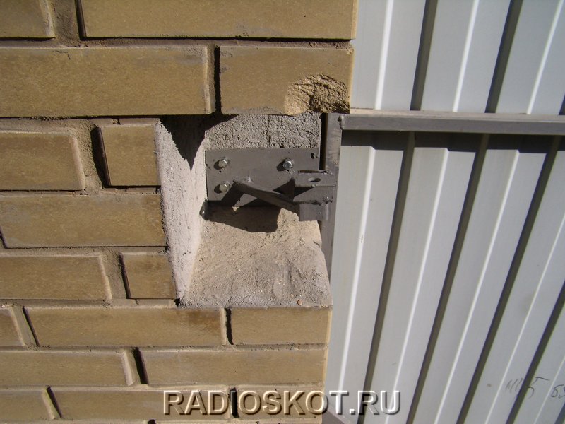
The photocell closest to the electric drive (receiver, RX) requires a 4-wire wire - 2 wires for power supply, and 2 more control contacts. In the diagram this wire is designated 4x0.35. It goes from the pole to the drive. They often forget that 4-wire cables are needed and put 2-wire cables, be careful. If possible, it is better to hide this cable in a pole, leaving a free end of 15-20 cm. If this is not possible, you need to strengthen the wire on the pole, fortunately there are now enough fasteners for the wire. Often this wire is laid in the seams between bricks and then sealed with mortar.
The photocell on the pole farthest from the drive (TX) requires a 2-core cable; in the diagram it is designated 2x0.35. It is better to do the wiring again with the same signal wire 4x0.22, you can use 2 wires, or you can use all the wires by twisting them in pairs. The wire of this photocell passes under the opening, so make sure that it is reliably protected, because vehicles will pass from above.
Still have questions? Call and our managers will be happy to advise you on all questions! Call or request a consultation.
The automatic gate connection diagram begins with the following steps:
- Preparing pillars for support.
- Preparing the foundation for automatic gates.
- Carrying out wiring for automation.
- Gate manufacturing.
- Carrying out installation.
The first priority is reliable support
The first thing you need to do is to correctly install the pillars under the support, where you will later need to attach automatic gates. The material for the pillars can be brick, concrete, channel or oak beams. It is recommended to concrete the pillar (depth) from 1 meter, then all the pillars are installed at the same level and filled with mortar. The curing time for concrete varies within seven days.
Important! Using pillars made of concrete or brick, provide for the placement of metal mortgages, three on each of them, equally spaced from the edge 10 centimeters from the side of the opening.
Preparing the foundation
To pour the foundation under the base of the gate, we use a channel, the width of which should be 20 centimeters, and reinforcement with a cross-section of 12-16 millimeters. We cut the reinforcement to 1 or 1.2 meters in length, then weld both sides to the channel flanges.
Our next action is to dig a hole, the length of which will be 50 percent of the width of the sliding gate opening. The dimensions of the pit itself should not exceed:
- width – 40 centimeters;
- depth - up to 1.5 meters.
The channel should be installed with the shelves facing downwards, and then concrete is poured into the hole. Having done everything as needed, we get the foundation for automatic (sliding gates).
Attention! The period for laying the foundation according to all norms and rules is 28 calendar days.
Without automation, nowhere
The electrical circuit of automatic gates depends on their type. So, today, there are three main types of automatic (sliding) gates, the connection diagrams of which are shown in the figures below.


Important! To avoid damage to the transformer, motor or control board and ensure stable operation of automatic gate automation, install voltage stabilizers. Thus, the price for possible repairs will be significantly reduced.
Do-it-yourself automatic gates, manufacturing diagram
The very first thing to decide is the type of material that we will use. To make a gate frame you will need profile pipe. So, armed with a grinder, we remove scale from the pipes.
Attention! When working with an angle grinder, do not forget to use special glasses to protect your eyes.

Having finished, we begin the process of welding the frame of our gate. A drawing diagram of an automatic gate, or as it is also called an automatic gate diagram, will help us in this matter. garage doors. As an example, see the picture below.


Having formed the outer frame, we weld the inner frame inside, which will give the structure rigidity and will serve for future fastening of wood, metal, corrugated sheets...
For a frame placed inside, pipes of 20*30, 20*40 millimeters are ideal. We weld them with tacks of two centimeters at intervals of 20 or 30 centimeters. A guide is welded at the bottom. We attach the guide and pipes in a checkerboard pattern.
We clean the welds and reapply anti-corrosion primer to the areas that were damaged. We wait for the soil to dry and begin painting the gate.
Important! It is better to apply the paint in two layers.

After completing the painting work, we sew up the canvas using self-tapping screws or rivets, attaching it to the pipe that is located inside.

What? Where? How? Or do-it-yourself gate installation
After the foundation is in place, we proceed to installation work. To avoid any difficulties during the process, you can ask advice from specialists or find information on the Internet simply by entering automatic gates, installation diagram or automatic gates, installation diagram into a search engine.
The procedure itself is quite simple and consists of welding the hinges to the load-bearing bases and sashes.
When performing installation, do not forget to leave a gap between the doors and a gap in the middle of the ground and the canvas, which can later be hidden by the speed bump. The bolts that will secure the doors should be welded to the internal frame.

You will learn about the assembly electrical diagram control with your own hands. We'll tell you how to connect different types engines and assemble starting equipment, and also reveal secrets soft start and stopping automatic sliding gates.
Depending on the selected engine type, you can use different ways connections. Not only the scheme will be different electrical connections, but also valid parameters current
Attention! When working with electrical part do not forget about safety precautions: weld a bolt to the stationary frame, which will be used to connect to the ground loop.
Motor connection
Three-phase motor on Rated voltage 380/220 V must have a star connection when connected to three-phase network nutrition. You can change the direction of rotation by swapping the connection of any two of the three phases.
If you are trying to connect three phase motor To single-phase network, give preference to the capacitive method. In this case, use a starting capacitor with a obviously higher capacity (2-3 times) and add a pair of compensating capacitors for the two remaining windings in working assembly, or consider turning off starting capacitor using a time relay. The capacity of the working capacitor is selected at the rate of 70-80 uF per 1 kW of power, and the nominal value is 450 V.

Single phase capacitor motor has four wires in the assembly, that is, two ends of the starting and working windings. The standard terminal block pin markings are as follows:
- Terminals U1 and U2 (or B1 and B2) are the main winding.
- Terminals W2 and V2 (or C1 and C2) - starting winding.
- Terminals V2 and V1 are the starting capacitor.
Connection starting winding remains constant, while the polarity of the power supply to the working winding can be changed to change the direction of rotation.
Note: The polarity is determined by the position of the jumpers on the motor terminal strip, the closure of which will be performed remotely through the contactor.
Launch equipment
To assemble the electrical circuit you will need two magnetic starter IEK KMI 1121 with a coil supply voltage of 230 V, or one reversing starter PML 2561 (the advantage of the latter is the presence of a mechanical interlock). There should be three main contacts.
It is also necessary to have a block of an auxiliary contact group, including one normally open and one normally closed contact. Additionally, you will need an IEK KP103 push-button housing with three buttons “Start”, “Reverse” and “Stop”. To install the post on the street side, it is recommended to equip it with key-locked buttons. All switching electrical equipment must be mounted in a metal box with a degree of protection IP54 and glands for wires.

Connect the input contacts of the two starters in parallel, supplying them with phase and neutral from the 220 V network through a circuit breaker. On the back side of the starters, connect two power wires to the starting winding.
Using the AIR 80 engine as an example, power must be supplied to terminals V1 and W2. Please note that the polarity remains the same regardless of which starter is turned on. Terminals U1 and U2 belong to the ends of the working winding and must be connected to the two starters in different sequences.
Power to the coils of each starter must be supplied through its own normally open and normally closed contacts of the second starter. This will ensure self-catching and keep the coil in the on state, and also provide electrical blocking of the oncoming start.
Push-button stations and limit switches
The drive is controlled by one or more push-button stations. Phase wire is passed through the series-connected normally closed contacts of the “Stop” buttons, which is necessary to be able to break the coil holding circuit from any button.
Next, power is supplied to the normally closed contacts of the “Start” and “Reverse” buttons, then from the terminals of each button power is supplied to the normally open pair of the opposite one. These contacts control the activation of the coils of the corresponding starters. Cross-connection via normally open contacts is necessary to avoid unintentional switching of starters.
In order for the drive to turn itself off in a timely manner when the gate reaches the extreme points of opening and closing, the electrical circuit must be supplemented with limit switches. VPK-2112 or ME 8104 switches with one normally closed contact. It is recommended to use products equipped with a roller.
Limit switches must be rigidly fixed to the stationary gate frame so that the roller is 1-2 mm from any longitudinal element of the gate. This can be a supporting frame or a rail guide, the main thing is that side surface was absolutely smooth. The gate must be placed first in the open, then in the closed position and mark the points of contact with the rollers.
Note! Since massive gates continue to move by inertia, it is recommended to move the marks a few centimeters in the opposite direction so that the limit switch is triggered with a slight advance.
According to the applied marks, you need to weld small protrusions, the height of which will be sufficient for reliable operation of the switch. It is also important that the tag is of sufficient length and holds the roller, and does not slip through it, briefly turning on the limit switch. The switch must be in the trip position until it begins to move in the opposite direction, when it leaves the mark and closes the circuit again.
The electrical connection of limit switches can be done in two ways.
 Connection diagram for push-button posts and limit switches
Method number 1. The normally closed contacts are connected in series and are included in the holding circuit of the contactor coils. The switching point is located between the series-connected “Stop” buttons and the normally open contacts of the starters. The disadvantage of this method is that when turning on the gate, you need to hold the button pressed for a certain time until the switch leaves the operation position.
Method number 2. It implies independent activation of limit switches in the coil holding circuits of each starter. The normally closed contact of the switch is located according to the scheme between the normally open auxiliary contact of the starter and the coil terminal. It is also allowed to place the switch in the electrical interlocking circuit: between the coil of one and the normally closed contact of the second starter. Thus, the switches operate independently of each other, which means that there is no time delay required when turning on the drive.
Gate control via frequency converter
Since frequency converters are Lately are becoming more and more accessible and popular, it is appropriate to use them to control the gate drive, especially since there is more than one reason for this:
- Since the frequency converter supplies the drive three phase voltage, you save by buying a more common engine of lower power.
- Engine speed does not matter.
- Difficulties with connecting a three-phase motor are eliminated.
- You avoid problems with starting the drive under load.
- The converter smoothly but quickly accelerates and stops the gate, opening occurs in a matter of seconds.
- No need to buy and install a gearbox.
- No need for starters, simple electrical circuit.
- The service life of the engine is significantly increased.
The average cost of a device with an output power of 2-2.5 kW is $250-300, so its purchase is quite justified taking into account the refusal to purchase a gearbox and starters.
The CFM-240 frequency converter is a budget option device, it also has the most common connection and control scheme. Following his example, you can easily understand similar devices.
 Frequency converter connection
Terminals L and N are used to supply, respectively, phase and zero from the 220 V network; it is important to observe polarity here. Terminals U, V and W provide the output voltage for three-phase power supply asynchronous motor for a voltage of 380/220 V, the windings of which are connected in a triangle. Control occurs by closing one of the control contacts DI1-DI3 to the common GND terminal. Accordingly, when DI1 and GND are closed, the motor starts, DI2 and GND will start the drive in the opposite direction, and DI3 and GND will stop it.
Principle of setting the frequency converter
Configuring the converter is done by changing the values of each of the 70 parameters. Full description functions and set values are indicated in the device passport. To adjust the values, you need to enter the parameter selection menu by pressing the “Mode” button until P--- is displayed on the display. Then you need to press “enter” and use the “up” and “down” arrows to select the number of the desired parameter, press “enter” again, set the desired value and press “enter” again to save.
Using a frequency converter gives some additional features. For example, you can use the positioning function by transferring data from the gate position sensor to the inverter. This will allow you to use the device in stepper motor mode. It will smoothly accelerate the gate and gently stop it at the extreme point, remembering both extreme positions of the door leaf. This is a more convenient and advanced replacement for the limit switch system. You only need to install a “quadrature encoder” type counter on the drive mechanism shaft.
The meter has two power wires that connect to the +12V and GND terminals, as well as two signal wires that connect to terminals DI5 and DI6. The positioning function is enabled by setting the value “2” to parameter 60. Next, you need to set the value “1” to parameter 61 to set desired type sensor Then, changing the values of parameters 62 and 63, determine the relationship between the number of pulses and the distance traveled.
For example, the motor shaft can move the gate 25 cm per revolution, and the encoder mounted on the shaft produces 200 pulses per revolution. This means that for every 1000 mm set in parameter 62, there will be 800 sensor pulses set in parameter 63.
Parameter 66 determines the type of braking; it must be assigned the value “1”. Parameter 67 determines the engine speed to which the maximum operating speed will be reduced, and the value of parameter 68 determines the required braking distance. Having configured the specified parameters, you can go to the main menu and specify the distance that the gate must travel, in millimeters. After completing the task, the counter will be reset to zero and will be ready for a new cycle, counting in both directions.
The rated motor rotation speed is set by the output frequency (Hz) in the main menu of the program. You can change it in real time and increase it as long as the transmission mechanism remains stable. Also remember that too much acceleration will not allow the converter to effectively reduce speed at the end of the path. Drive acceleration time to maximum speed is specified by the value in seconds of parameter 10.
Setting gate braking using a frequency converter
Gates that are too massive require braking by the drive. For this purpose, the frequency converter has a function enabled by parameter 21. The braking force and the time required to complete a stop are set by parameters 27 and 28, respectively. When braking by the drive, load compensation must be used. To do this, to power terminals Br you need to connect power resistors with a resistance of at least 70 Ohms and a power of over 350 W (they can also be replaced with a bunch of 4-5 incandescent lamps connected in series).
Now you have several options for connecting the motor and can choose the method that suits your needs. Each connection method can have a remote control circuit, which we will discuss in the next article.
 (1 ratings, on average: 5,00 out of 5)

