Intentional electrical connection. About functional grounding
Protective measures in electrical installations. Protective measures for indirect contact
An important measure to ensure the electrical safety of personnel servicing electrical installations is protective grounding or grounding of metal non-current-carrying (structural) parts of electrical installations and electrical equipment that are not normally energized, but may become energized relative to the ground in emergency modes (in the event of insulation damage).
Grounding called deliberate electrical connection any point in the network, electrical installation or equipment with a grounding device.
Grounding is divided into:
- working grounding;
- protective grounding.
PUE give the following basic definitions regarding grounding:
Working grounding is called the grounding of a point or points of current-carrying parts of an electrical installation, performed to ensure the operation of the electrical installation (to ensure proper operation of the installation in normal and emergency modes).
Working grounding can be carried out directly or through special devices(resistances, arresters, reactors, etc.)
Protective grounding in electrical installations with voltages up to 1 kV, the deliberate connection of open conductive parts with solidly grounded neutral generator or transformer in networks three-phase current, with solidly grounded source output single-phase current, with a grounded source point in networks direct current performed for electrical safety purposes.
Neutral protective conductor- a protective conductor in electrical installations up to 1 kV, intended for connecting open conductive parts to the solidly grounded neutral of the power source.
Zero working (neutral) conductor (N)- a conductor in electrical installations up to 1 kV, intended for powering electrical receivers and connected to a solidly grounded neutral of a generator or transformer in three-phase current networks, with a solidly grounded terminal of a single-phase current source.
Grounding device- a set of grounding conductors and grounding conductors.
Grounding conductor- a conductor connecting the grounding point to the ground electrode.
Ground electrode - a conductive part or a set of interconnected conductive parts that are in electrical contact with the ground directly or through an intermediate conductive medium.
Voltage on the grounding device - voltage that occurs when current flows from the ground electrode into the ground between the point of current input into the ground electrode and the zero potential zone.
Grounding device resistance - the ratio of the voltage on the grounding device to the current flowing from the ground electrode into the ground.
Grounding serves to convert a frame fault into a ground fault in order to reduce the voltage across the frame relative to ground to a safe value.
Protective grounding
Main purpose protective grounding:
- eliminating the risk of injury electric shock in case of touching the housing or other non-current-carrying metal parts of the electrical installation that are energized.
Protective grounding is used in 3 phase networks up to 1 kV s isolated neutral and in networks above 1 kV with any neutral mode. The schematic diagram of protective grounding is shown in Fig. 4.7.

Fig.4.7. Schematic diagrams protective grounding (a) in a network with an isolated neutral and (b) in a network with a grounded neutral.
1 - protective equipment housings;
2 - protective grounding conductor;
3 - ground electrode of the working grounding of the neutral of the current source; R3 and Ro - resistance of protective and working grounding.
The operating principle of protective grounding is based on reducing the voltage between the energized housing and the ground to a safe value.
Let us explain this using the example of a network up to 1 kV with an isolated neutral.
If the body of electrical equipment is not grounded and it is in contact with a phase, then touching such a body by a person is tantamount to touching phase wire. In this case, the current passing through a person can be determined by formula (2.5).

With low resistance of shoes, floor and wire insulation relative to the ground, this current can reach dangerous values.
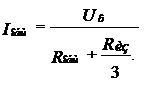
If the body is grounded, then the current passing through a person when R rev= Rn= 0 can be determined from the following expression:
 (4.1)
(4.1)
This expression is obtained as follows:
from a grounded case (Fig. 4.8), the current flows into the ground through the ground electrode ( I z) and through a person ( Ih). The total current is given by:
Where:
R total - total resistance of parallel connected R z And R h:
![]()
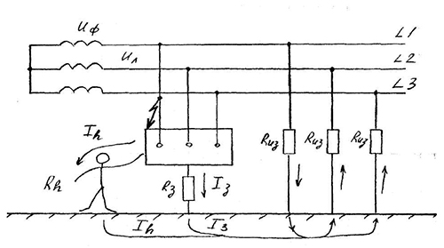
Fig.4.8. On the question of the principle of protective grounding in a network with an isolated neutral.
From the diagram in Fig. 4.8
I h ×R h =I z R z = I total ×R total, where the current through the human body will be:

Having performed the simplest transformations, we obtain expression (4.1).
At low R z compared with R h And R from this expression simplifies:
 (4.2)
(4.2)
Where:
R z- housing grounding resistance, Ohm
At R z= 4 Ohm, R h=1000 Ohm, R from=4500 Ohm, the current through the human body will be:
![]()
This current is safe for humans.
The touch voltage in this case will also be insignificant:
U pr=I h × R h = 0.00058×1000=0.58 V
The less R z- the better the protective properties of protective grounding are used.
Content:During the operation of electrical equipment, the need arises to use grounding devices. Depending on the purpose, protective and working grounding can be used. In the first case, the safety of personnel working at electrical installations is ensured, and in the second case we are talking about normal operation devices in normal and emergency modes. Both grounds are different and cannot be used together. In order to better understand the purpose and principle of operation, you need to take a closer look at each of them.
What is called protective grounding
Protective grounding devices are made by making a deliberate electrical connection to the ground metal parts, to which electric current is not supplied and which may unexpectedly become energized.
The main function of protective grounding is considered to be reliable protection people from electric shock in case of contact with metal non-current-carrying parts that are energized by various reasons mainly due to insulation damage.
Protective grounding should not be confused with working and re-grounding, zero protective conductor. Its action is primarily aimed at reducing step and touch voltages generated during a short circuit to the housing to a safe value. This is achieved by reducing the potential of the grounded equipment by reducing the resistance of the grounding device. At the same time, the potentials of the base where the person is located and the grounded equipment itself are equalized.
Protective earthing is used in the following areas:
- V, voltage up to 1 kV s.
- In single-phase two-wire networks alternating current, isolated from the ground, with voltage up to 1 kV.
- In two-wire DC networks, in which the middle point of the current source windings is isolated.
- In AC and DC networks with any modes of current source windings at a voltage of more than 1 kV.
Direct contact with the ground or its equivalent is carried out using grounding conductors. They are divided into two main types:
- Artificial ground electrodes. Used for grounding purposes only. They are made from various steel structures and should not be painted. To protect against corrosion, galvanized coating, an increased number of grounding conductors, and a special electrical protection. In some cases, electrically conductive concrete can be used as a grounding conductor.
- Natural grounding. For this purpose, electrically conductive parts of networks and communications in buildings and structures that are in contact with the ground are used. It is recommended that electrical installations be grounded first of all. natural grounding agents. Water supply pipes and heating systems, structures of buildings and structures made of metal and reinforced concrete, rail tracks, lead cable sheaths, etc. should be used. Do not use pipelines that carry flammable liquids, gases or mixtures.
What is called working grounding?
Working grounding is considered to be the intentional connection to the ground of certain points found in electrical circuits. First of all, these are the neutral points of generator and transformer windings. Reliable conductors are used as connections, as well as special equipment in the form of breakdown fuses, arresters, resistors, etc.

The main purpose of working grounding is to create obstacles to failures and short circuits, to maintain the system in the event of an emergency. Under its influence there is a decrease electrical voltage in parts and parts of the mechanism that are directly under voltage. Taken measures help localize electrical faults, remove them and prevent further spread.
In accordance with safety regulations, it is prohibited to combine protective and working grounding. This is due to the fact that various interference currents, such as atmospheric electrical discharges, can superimpose on the currents flowing in single-wire circuits. This may lead to violations external relations devices and even equipment damage. In addition, such combinations may render the voltage protection ineffective. When emergency situations it will function as a worker or will not function at all.
The working ground resistance should be no more than 4 ohms. This limitation is associated with the magnitude of the voltage arising relative to the ground at neutral wire, during the flow of ground fault current through the working ground. This is especially true when the high voltage transformer winding is shorted to the low voltage winding.
Functional grounding.. Protective grounding.. Sources of interference in grounding networks.. Methods of protecting equipment from interference.. Network with isolated neutral.. Galvanic power supply isolation.. Isolating transformer.. Equipment electromagnetic compatibility (EMC).. Functional grounding options. . Reconstruction of existing facilities.. Design of new facilities.. Independent functional grounding.. Main grounding bus (GZSh).. Functional grounding bus (SFZ).. Zero potential zone.. Protective bus PE.. Functional bus FE.. Potential equalization bus .. Functional grounding resistance.. Justification of design solutions.. Functional grounding box..
Functional (working) grounding is used for the normal functioning of an electrical installation or equipment, i.e. for their normal operation, not for electrical safety purposes, therefore its use as the only grounding system is strictly prohibited.
This type of grounding can be combined with protective grounding or performed in addition to it based on the requirements of the equipment manufacturer, customer or regulatory documents.
Protective grounding is often a source of overvoltages and conducted interference in low current systems automatic control, measuring, information or other interference-sensitive equipment, which prompts a search effective ways protection of such equipment from various types of interference and overvoltage.
Methods for protecting information equipment from interference
1. Network with isolated neutral.
A radical solution to the problems described above with protective grounding interference is the use of galvanic isolation from the power supply (IT network) with separate grounding of the power and measuring parts of the system, which eliminates the flow of interference currents from the power ground.
Galvanic isolation can be carried out using an isolating (isolating) transformer or using autonomous power supplies: galvanic batteries and batteries.
The basic idea of galvanic isolation is that in electrical circuit The path through which conducted interference can be transmitted is completely eliminated. Since in such a network there is no galvanic connection between the ground, phase and neutral, a closed current loop with the ground is not formed and touching any of the power outputs of the isolation transformer is safe. Ground leakage currents are microamps, which is significantly less than the safety current level and does not pose a threat to humans.
The isolation transformer, in addition, is good protection against pulse and lightning overvoltages, which provides more reliable operation connected equipment.
Thus, high reliability, electrical safety and noise immunity of networks with an isolated neutral are their undeniable advantages.
At the same time, use of isolation transformers with insulation monitoring systems (IMS) requires quite a lot of expenses and a legitimate question arises about the appropriateness of such expenses. This topic deserves.
2. Electromagnetic compatibility of equipment (EMC).
In most cases, failures and failures in the operation of automation systems, computing and measuring equipment can be avoided by complying with the requirements electromagnetic compatibility equipment and rules for grounding such systems:
Use of equipment that meets the requirements of relevant electromagnetic compatibility (EMC) standards;
Application of surge protection devices in supply feeder circuits;
Connection of metal sheaths of cables to a combined potential equalization system;
Separation of power and signal cables and correct execution their intersections;
The use of signal and information cables that meet the manufacturer’s requirements for electromagnetic compatibility;
Power and signal cables must be separated from the down conductors of the lightning protection system minimum distance or by shielding in accordance with IEC 62305-3.
Low-current microprocessor devices must be powered from uninterruptible power supplies (UPS) that have noise-suppressing network filters.
Extended external power supply networks must be laid with a cable with a shielding sheath connected to the existing protective grounding circuit.
The connection of the functional and protective grounding conductors in order to equalize the potentials between them must be carried out at one point on the SUP or GZSh bus - leakage currents along the PE conductor should not fall on the cable screens.
3. Correctly performed grounding. This is one of the main and available methods for reducing impulse noise and overvoltage, which lead to malfunctions during the operation of low-current microprocessor equipment. Proper grounding usually solves the problem O most of the issues of reducing overvoltages and interference.
4. Potential equalization between grounding devices for various purposes is the main condition for ensuring the electrical safety of personnel. In rooms intended for the operation of equipment sensitive to interference, a potential equalization system must be installed. Along the inner perimeter of the building there should be a ring connecting conductor connected to the main grounding bus. Ring potential equalization conductors should also be located on each floor. An example of the internal circuit of a potential equalization system around the perimeter of a building is shown in rice. 1.

Rice. 1
Functional grounding options
1. Reconstruction of existing facilities.
In this case, due to the operating conditions of information equipment, a low-impedance grounding conductor is often required, which is performed in addition to the existing protective grounding of the building's electrical installation.
According to PUE 1.7.55 " First of all, the requirements for protective grounding must be met." In other words, the first place must be to protect people’s lives and health. Accordingly, the functional grounding bus (FGB) must be connected to the protective grounding on the main grounding bus (GGB) of the main potential equalization system of the electrical installation of the building, as shown in rice. 2.
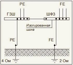 This grounding scheme allows you to ensure electrical safety in accordance with the requirements GOST R 50571-4-44-2011 (IEC 60364-4-44), and PUE ch. 1.7 provided that the existing protective grounding is carried out in full accordance with the PUE.
Experience in the reconstruction of existing facilities shows that almost all facilities, especially those that have been in operation for 10 years or more, exhibit certain grounding deficiencies: corrosion of grounding devices, non-compliance with grounding resistance requirements, non-compliance with electromagnetic compatibility requirements...
Therefore, before installing information equipment it is necessary to conduct an inspection of protective grounding devices. The inspection of grounding devices includes: external inspection, opening (if necessary) of conductors located in the ground, as well as a set of measurements of the parameters of grounding devices.
Based on measurement results An appropriate amount of work must be carried out to restore the protective grounding parameters, which is advisable to combine with the installation of functional grounding and the transition (if necessary) to a TN-S or TN-C-S power supply system.
Low resistance functional grounding conductor in this case, it is advisable to perform it according to a “radial” grounding scheme, which ensures stable operation of the equipment. In cramped conditions, it is possible to use a composite, deep ground electrode.
Functional grounding has its own requirements for grounding resistance, corresponding to the requirements of the equipment manufacturer or departmental standards. For example, for computer technology and information science, according to SN 512-78 Grounding resistance should be no more than 1 Ohm, for highly sensitive medical equipment in accordance with Design manual for SNiP 2.08.02-89– no more than 2 Ohms, etc.
2. Design of new facilities.
 Rice. 3
When designing new objects, it becomes possible perform a grounding device for repeated protective grounding at the entrance to the electrical installation of the building at required functional grounding resistance
, which must be simultaneously used for all types of building equipment.
Grounding device diagram repeated protective grounding to the required functional grounding resistance is shown in rice. 3.
In a buiding a main grounding bus (GZSh) is installed, to which the following are connected: a grounding conductor for repeated protective grounding, a PEN conductor, a conductor of the potential equalization system, a PE bus of the supply line in the TN system, a grounding device for the lightning protection system of the 2nd and 3rd categories, as well as a bus functional grounding (SFG).
Such a scheme V Lately is widely used in the design of new facilities and corresponds to high level electrical safety.
3. Independent functional grounding.
Sometimes the functional grounding conductor must be placed separately, outside the influence zone of natural and artificial grounding conductors of the building's electrical installation.
Performing functional grounding not associated with the protective grounding device and the main building potential equalization system, should be treated as a special case,in which special measures must be taken to protect people from electric shock, excluding the possibility of simultaneous contact with parts connected to the potential equalization system of the electrical installation of the building and to parts of equipment connected to an independent grounding device for functional grounding.
There is always the possibility of a potential difference occurring between separate grounding systems, if these grounding systems are within the non-zero potential zone. A dangerous potential difference can arise, for example, when short circuit on the housing of electrical equipment in the TN-S network (before the protection system is triggered), when lightning protection is triggered (step voltage), when exposed to external electromagnetic fields, etc.
From an electrical safety point of view option of independent functional grounding (not associated with a protective grounding device) is acceptable And m, if the equipment is powered by an isolation transformer or the grounding switches for different purposes are located at such a distance that there is a zone of zero potential between them. The distance between these two earthing conductors must be ≥ 20 m.
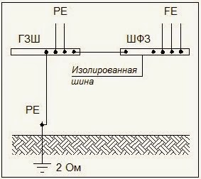
More details about geographically close and independent grounding devices, see the articleThe independent functional grounding diagram is shown in rice. 4.
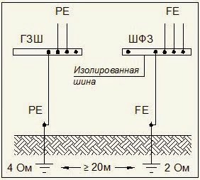 The need for independent functional grounding may arise, for example, when the manufacturer of information equipment directly indicates the need for autonomous grounding (without a separate “functional ground” the equipment does not work). In this case, the manufacturer provides two grounding bars in the equipment cabinet:
protective PE;
functional FE.
Function bus FE isolated from the cabinet body. The shields of the signal (control) cables are connected to it. The FE bus is connected with a copper insulated cable (to avoid contact with metal structures building) with a cross-section of at least 1x25 mm2 with a grounding conductor located at a distance of at least 20 m from the protective (or any other) grounding conductor. Protective grounding of the cabinet body is carried out with a PE conductor to the potential equalization bus connected to the main grounding bus. Note that this FE bus inside the cabinet is provided by the equipment manufacturer itself.
By way of illustration on rice. 5 a variant of independent functional grounding not associated with a protective grounding device is presented. 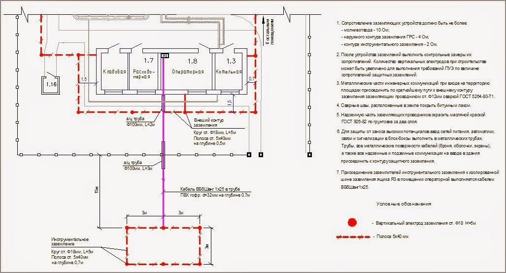
Rice. 5
Justification of design decisions
To avoid any difficulties with the approval and delivery of the project, you need to be careful when receiving the design specifications. If equipment that is sensitive to interference is used at the facility being designed, then you must immediately request certificates from the customer or manufacturer for this equipment, where the need for an independent grounding device must be justified and the required functional grounding resistance must be indicated. Passports (certificates) for the equipment used are attached to the project and serve as justification for design decisions at all stages of project approval.
Independent functional grounding is carried out according to the diagram on rice. 4.
If an independent functional grounding switch is not provided by the equipment manufacturer, then in this case functional grounding must be performed according to one of the schemes ( rice. 2, 3) taking into account the requirements for electromagnetic compatibility. In this case, an isolated functional grounding bus can be installed in a separate grounding box, which prevents simultaneous contact with parts that may be exposed to a dangerous potential difference if the insulation is damaged.
Example such a functional grounding box is shown in rice. 6.
 (1 ratings, on average: 5,00 out of 5)

