Isolated neutral circuit. Isolated neutral. Device and work. Application
Electrical networks, as you know, are divided depending on the voltage class - up to and above 1000V. Neutral is a common winding point for transformers and generators connected in a star. If the winding circuit is a triangle and zero is needed, then we can recall the circuit. We will only consider networks alternating current.
Types of neutral grounding in networks up to 1 kV
IN electrical networks voltage up to 1000V, it is customary to use three neutral grounding systems - these are TN, IT, TT. Each of the letters has a specific meaning, let's figure it out:
- The 1st letter describes how the neutral of the power supply is grounded.
- T (terra) - dead-earthed neutral
- I (isolate) - neutral is isolated (and - isolated, easy to remember)
- The 2nd letter shows the method of grounding exposed conductive parts (HFC) to earth
- N (neutral) - HFCs are grounded through a solidly grounded neutral of the power supply
- T - HRE are grounded regardless of the power supply
In turn, the TN system is divided into three subsystems - TN-C, TN-S and TN-C-S. Within the framework of this subsystem, the third letters (C - combine, S - separe) denote the combination or separation in one wire of the functions of the zero protective (PE) and zero working (N) conductor.
Let us now consider each system in more detail.
TN earthing system
In this system, the neutral is solidly grounded, and the exposed conductive parts are grounded through this solidly grounded neutral. Solidly grounded - this means that the neutral is connected directly to the grounding device (by bolt, welding) or through a low resistance (current transformer).
In networks up to 1 kV, a grounded neutral is used to power single-phase and three-phase loads.
TT earthing system

The TT system assumes that the power supply neutral is solidly grounded, and the equipment HREs are grounded by a grounding device that is not electrically connected to the source neutral. That is, a protective PE conductor is created at the consumer himself, and does not come from a power source.
IT grounding system
In an IT system, the neutral of the generator or transformer is isolated or grounded through high impedance devices, and the HREs are independently grounded. This system is not recommended for residential buildings, used where the first earth fault does not require power interruption. These can be electrical installations with increased requirements for the reliability of electricity supply.
Types of neutral grounding in power networks above 1kV
In networks with voltages above 1000V, an isolated (ungrounded) neutral, an effectively grounded neutral and a resonantly grounded neutral are used. A dead-earthed neutral is used only in networks up to 1kV.

Historically the first grounding system. The neutral point of the power supply is not connected to the grounding device. The windings are connected in a triangle and it turns out that there is no zero point. It is used for voltage 3-35kV.
This type of grounding is used in networks with voltages above 110 kV. The advantage is that for single-phase faults on undamaged phases, the voltage to earth will be 0.8 phase-to-phase in normal operation. In this system, the ground loop itself is made taking into account the flow of high short-circuit currents, which makes it complicated and expensive.
It is used in networks 3-35kV. Used to reduce the magnitude of short circuit currents. Historically, it was the second way to ground the neutral. Grounding through a resistor is used all over the world, through a reactor - in the countries of the former Soviet Union.
Grounding through the reactor - in the absence of a short circuit, the current through the reactor is small. When a phase-to-earth fault occurs, a capacitive short-circuit current and an inductive reactor current flow through the fault. If their value is equal, then there is no current in the place of the circuit (resonance phenomenon).
Grounding through a resistor can be low-resistance and high-resistance. The difference in the amount of current generated by the resistor when a ground fault occurs. High-resistance is used in networks with low capacitive currents, in which case the short circuit does not need to be turned off immediately. Low-resistance grounding, on the contrary, is used for high capacitive currents.
The choice of types of neutral grounding depends on the following factors:
- network capacitive current value
- admissible value of single-phase short circuit
- the possibility of switching off a single-phase circuit
- type and type of relay protection
- personnel safety
- availability of a reserve
If you do not want to lose this material, then share it with your friends on social networks!
Another way to prevent the occurrence of an arc and the associated overvoltages during a single-phase earth fault is dead earthing of the neutral. A solidly grounded neutral is a transformer or generator neutral connected directly to a grounding device.
Single-phase earth fault (e.g. phases A) in systems with deaf grounded neutral(Fig. 1.5) is a short circuit, since the damaged phase is short-circuited through the ground and neutral of the transformer or generator. The current at the fault location is limited only by the resistances of the power supplies and is therefore a short circuit current. At the same time, the fault current is practically not: it depends on the value of the insulation resistance and the capacitance of the system relative to the ground, since Y 0 » Y A ; Y 0 » Y B ; Y 0 » Y c ; Y 0 = l/r 3 , so the current. single-phase short circuit earth , e.g. phases A, is defined by the expression
those. with deaf grounding of the neutral (r 3 -> 0; Y 0 -> ∞) the value I 3 A may have very great importance(thousands of amps). The voltages of the undamaged phases relative to earth are determined by the geometric sum of the normal stresses U " B And U " C and small additional components due to the resistance of the windings of transformers and supply wires; but the quantities U " B And U " C less than 0.8 U L .
In the event of a single-phase earth fault in a system with a dead-earthed neutral, the single-phase short-circuit current suppresses the capacitive current and activates the relay protection, which disconnects the damaged section of the system.
I 3A U’ C U’ B
Rice. 1.5. System voltage above 1000 V with solidly grounded neutral:
a-design equivalent circuit in emergency mode; b- vector diagram of stresses.
The reduction of single-phase short-circuit currents in a system with a solidly grounded neutral is achieved by neutral grounding at some system transformers or by introducing a current-limiting resistance (active R or inductive L). Unearthing the neutral at some of the transformers in the system aims to reduce the current of a single-phase short circuit to the value of the current of a three-phase short circuit, which determines the necessary breaking capacity of the circuit breakers. However, in some cases, reducing the number of dead-grounded neutrals does not reach the goal, and the operation of the system becomes more complicated. Then you have to resort to grounding the neutral of the system transformers through resistance of one kind or another. But at the same time, it is not possible to completely get rid of overvoltages or an increase in the voltage of the “healthy” phases relative to the ground in emergency modes.
When grounding the neutral through inductive reactance X R(reactor), the current at the fault location will be significantly greater than the capacitive earth fault current, but not more than the permissible values, limited by the possibility of a stable arc fault to earth. The voltages of undamaged phases relative to earth in emergency mode are (0.8 ... 1.0) U l (insulation level - as in systems with isolated neutral). Neutral reactors increase the stability of the system in case of single-phase earth faults and limit switching overvoltages to acceptable limits.
When grounding the neutral through active resistance R current at the fault location will be greater than the capacitive earth fault current (but less than when earthing the neutral through X R), and the voltages of undamaged phases relative to earth can be higher than in a system with an isolated neutral (1.73 ... 1.9) £ / f. With the correct value R the stability of the system with single-phase earth faults is usually higher than with a dead-earthed neutral. From the point of view of switching overvoltages, systems with a neutral earthed through R are similar to systems with a solidly earthed neutral (the lowest). Neutral grounding via R is an effective measure to prevent overvoltages during ground fault transients, as R shunts the capacitance of the network, causing an aperiodic discharge process (the best results in this respect occur at a value of R, equal X C =1 / jЗωС or close to it. Reliability of neutral earthing through R higher than through x p. Current-limiting active and reactive resistances, grounding the neutral, usually choose such a value at which the earth fault current exceeds the possible maximum load current.
Systems with neutral earthed through R, compared to a system whose neutral is earthed through X R, have the following disadvantages: in order to achieve the same degree of limitation of the earth fault current, a large resistance value is required ( R), since the reactor resistance ( x p) is added arithmetically with the inductive reactance of the system, and consequently, the voltage in the system and the power loss during short circuits are greater; constructively fulfillment R more difficult, especially in high voltage and high power systems, and the cost of construction is higher than for reactors (cooling becomes more difficult).
Thus, the introduction of a single-phase short circuit into the neutral of the reactor to limit the current is a more economically feasible measure that has received appropriate distribution. The scope of the neutral grounding method through active resistance is limited mainly to generators and generator voltage networks.
The main advantages of a system with dead neutral grounding are as follows: the neutral potential is stabilized and the possibility of stable grounding arcs and their consequences is eliminated; the operation of insulation during earth faults and transients is facilitated, which makes it possible either to reduce the level of insulation (and therefore save in costs), or to increase the reliability of installations as a result of a greater margin of safety in insulation while maintaining the insulation level compared to other methods of neutral grounding; the implementation of clear, reliable, selective and fast relay protection is ensured; the operation of the system in relation to the neutral mode is facilitated.
However, a system with dead neutral grounding has a number of disadvantages: any single-phase ground fault is a short circuit and the relay protection immediately disconnects the damaged section, i.e. the uninterrupted power supply is disrupted, which requires the use of high-speed automatic reclosure devices to limit dead breaks and the implementation of redundant systems for the most responsible consumers, this leads to increased costs, additional investment and damage from undersupply of products; there is a significant electromagnetic effect on communication lines, which leads to an increase in the cost of protecting the latter; the cost of relay protection increases due to its three-phase design; short-circuit currents can reach very high values (exceed the currents of three-phase short circuits) during ground faults, which is the cause of dynamic destructive forces that extend to a significant part of the system (damage to the stator iron during insulation breakdown on the case, cable sheath breaks, destruction of insulator strings on power lines, etc.); at high short-circuit currents, the synchronizing torque decreases (synchronous motors can slow down, and stations operating in parallel can go out of synchronism); there is a risk of injury to people due to high contact and step voltages due to short-circuit currents during a single-phase earth fault; significantly increase the cost of grounding devices.
Blind grounding of the neutrals of electrical installations not only prevents the occurrence of arc surges in them, but also leads to lighter insulation in relation to the ground, which makes it possible to reduce costs, and the savings increase with increasing network voltage. In this regard, the dead-earthed neutral has found wide application in systems with a voltage of 110 kV and higher. If it is necessary to limit the current of a single-phase short circuit, the neutral of a part of the transformers is grounded.
Networks with dead-earthed neutral are also used in systems with voltages up to 1000 V. It is advisable to use it in three-phase power systems with a voltage of 220 and 380 V with a significantly branched network.
In modern power systems, networks of 110 kV and above are operated with effective grounding of winding neutrals power transformers. Networks with a voltage of 35 kV and below operate with an isolated neutral or grounding through arcing reactors.
Each type of grounding has its advantages and disadvantages.
In networks with isolated neutral single-phase short circuit to ground will not cause a short circuit. A small current flows at the fault due to the capacitance of the two phases to ground. Significant capacitive currents are usually compensated in whole or in part by the inclusion of an arcing reactor in the neutral transformer. The residual low current as a result of compensation is not able to maintain the arc at the fault, so the damaged area, as a rule, does not turn off automatically. A metallic single-phase earth fault is accompanied by an increase in voltage on undamaged phases to linear, and when a fault occurs through an arc, overvoltages may occur that spread to the entire electrically connected network, which may contain areas with weakened insulation. To protect transformers operating in networks with isolated neutral or with compensation capacitive currents, from the effects of increased voltages, the insulation of their neutrals is performed for the same voltage class as the insulation of the linear inputs. With this level of isolation, no means of protecting neutrals are required, except for valve-type arresters connected in parallel with the arcing reactor.
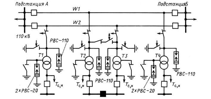
In networks with effective neutral grounding (Fig. 1.19), a single-phase ground fault leads to a short circuit. Current short circuit(Short circuit) runs from the fault location through the ground to the grounded neutrals of the transformers T1 And T2 distributed inversely with the resistance of the branches. The damaged section is put out of operation by the action of earth fault protection. Through transformers (TK And T4), the neutrals of which do not have a deaf ground, the current of a single-phase short circuit does not pass.
Taking into account the fact that a single-phase short circuit is frequent (up to 80% of short circuit cases in power systems are single-phase short circuits) and a severe type of damage, measures are taken to reduce short circuit currents. One such measure is the partial earthing of transformer neutrals.
The neutrals of autotransformers are not grounded, as they are designed to work with the mandatory grounding of the ends of the common winding.
The number of grounded neutrals in each section of the network is established by calculations and is taken as a minimum. When choosing grounding points for neutrals in the power system, they are guided both by the requirements of relay protection in terms of maintaining earth fault currents at a certain level, and by ensuring the protection of the insulation of grounded neutrals from surges. The latter circumstance is due to the fact that all 110-220 kV transformers of domestic plants have a reduced level of neutral insulation. So, for 110 kV transformers with voltage regulation under load, the neutral insulation level corresponds to the standard voltage class of 35 kV, which is due to the inclusion of switching devices with an insulation class of 35 kV from the neutral side. Transformers 220 kV also have a neutral insulation level lowered by a class. In all cases, this gives a significant economic effect, and the greater the higher the voltage class of the transformer.
The choice of the specified level of isolation of the neutrals of transformers intended for operation in networks with an effectively grounded neutral is technically justified by the voltage value that may appear on the neutral during a single-phase short circuit. And it can reach almost 1/3 of the line voltage (for example, for 110 kV networks, about 42 kV - effective value). Obviously, the 35 kV class insulation of the earthed neutral needs to be protected from overvoltages. In addition, during open-phase trips (or connections) of unloaded transformers with isolated neutral transition process accompanied by short-term surges. Enough reliable protection neutrals from short-term overvoltages is the use of valve arresters. The neutrals of 110 kV transformers are protected by 2xRVS-20 arresters with the highest permissible effective quenching voltage of 50 kV.
However, practice shows that not only short-term overvoltages can affect the neutral of transformers. Neutrals can be affected by power frequency phase voltage (for networks 110 kV 65-67 kV), which is dangerous both for the insulation of the transformer and for the arrester in its neutral. Such a voltage may appear and remain unnoticed for a long time (tens of minutes) in open-phase switching modes by switches, disconnectors and separators of unloaded transformers, as well as in some emergency modes.
Rice. 1.19..
Open-phase switching of unloaded transformers. On fig. 1.20 shows a three-phase transformer with isolated neutral. From vector diagram it can be seen that with a symmetrical mains voltage and circuit parameters, the magnetization currents and magnetic fluxes in the core are also symmetrical, i.e., , and the voltage on the neutral is zero.
When a transformer is switched phase by phase, its electrical and magnetic state changes. Turning on the transformer from the side of the winding connected to the star, with two phases (Fig. 1. 20, b) leads to the disappearance of the flow F With and the appearance on the neutral and on the disconnected phase of a voltage equal to half the phase: ![]()
![]()
Voltage at open contacts switching device
When voltage is applied in one phase, all windings of the transformer and its neutral will be energized by the switched phase. Between the open contacts of the apparatus, the voltage D U
=
U
l .
In operation, the delay in the elimination of open-phase modes of unloaded transformers has repeatedly led to accidents. The best measure to protect the reduced insulation of transformers from dangerous voltages is the deaf grounding of their neutrals. Therefore, before switching on or disconnecting from the network (disconnectors, separators or air circuit breakers) of 110-220 kV transformers, in which the neutral is protected by valve-type arresters, it is necessary to ground the neutral of the winding that is energized or disconnected, if another transformer with a grounded neutral is not connected to the same buses or to the supply line.
Tests have established that the deaf grounding of the transformer neutral facilitates the processes of switching off and on the magnetizing currents. The arc burns less intensely when the transformer is turned off and quickly goes out.
Disconnection of the earthing switch in the neutral of a transformer operating normally with a grounded neutral protected by a surge arrester should be carried out immediately after switching on the voltage and checking the full-phase switching on of the switching device. It is impossible to leave the grounded neutral for a long time, if this is not provided for by the network operation mode. By grounding the neutral, a change is made to the distribution of zero-sequence currents and the selectivity of the protection against single-phase earth faults is violated.
Power supply schemes from single and double passing lines of 110-220 kV substations, made according to simplified schemes, are now widely used. The number of transformers connected to the line is not regulated and reaches four or five. If two or more transformers are connected to the line (Fig. 1.21), then it is advisable to constantly (or for the duration of operations) have at least one of them have a dead neutral ground (transformers T2 And TK in fig. 1.21). This will avoid the appearance of dangerous voltages on the isolated neutrals of other transformers in the event of an open-phase voltage supply to the line along with the transformers connected to it.
Yes, at single-phase connection(phase IN) supply line under voltage (Fig. 1.22, a) in the cores of the disconnected phases of a transformer with a dead-earthed neutral T 1
close magnetic flux F
B undisconnected phase. He will induce in the phase windings A And WITH approximately equal emf mutual induction E
A And e With. Transformer T 1
will be in balanced single-phase mode.
With a single-phase symmetrical system of voltages at the linear terminals of the transformer (the sum of these voltages is zero), the voltage at the ungrounded neutral T2 relative to the ground is also zero: ![]()
Where ![]()
With two-phase switching (phases A And IN) supply line (Fig. 1.22, b) the core of the disconnected phase closes the total magnetic flux F
A +F
B =-F
C, which will induce mutual induction EMF in the winding of the disconnected phase E
C, equal in value and direction to the phase voltage U
c if it was enabled. Thus, a symmetrical three-phase voltage system is formed at the line inputs of all transformers connected to the line, at which the voltage on the isolated neutral of the transformer T2 equals zero: ![]()
Where ![]()
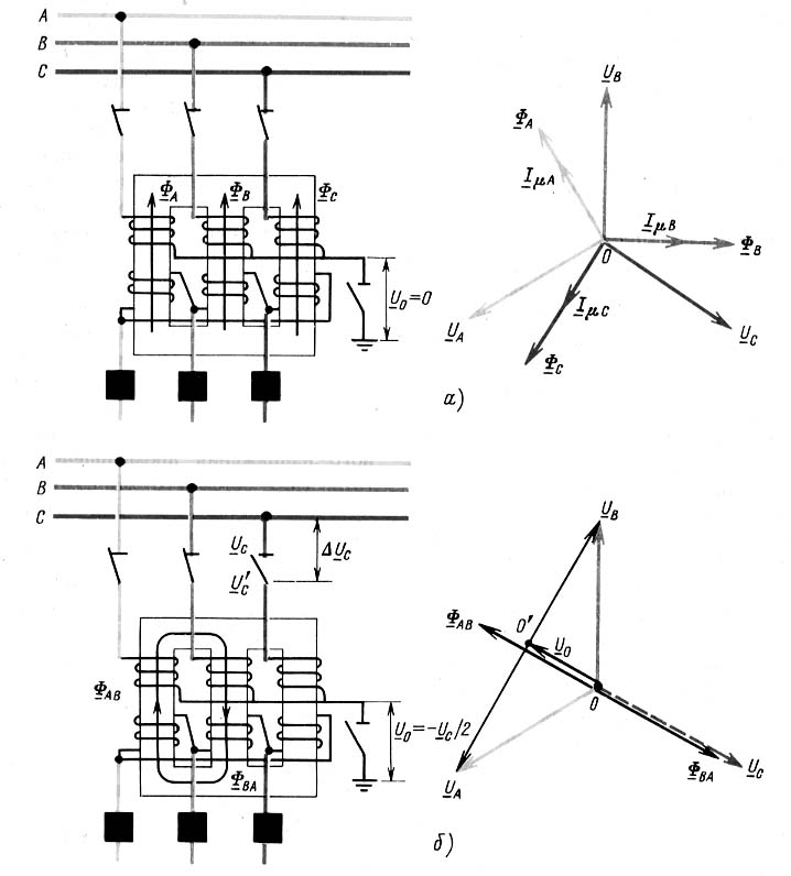
Rice. 1.20. Full-phase (a) and two-phase (b) modes of switching on an unloaded transformer with an isolated neutral
Rice. 1.21.
In networks with an effectively grounded neutral, transformers subject to dangerous overvoltages in emergency conditions, when, for example, when a wire is broken and connected to the ground, for one reason or another, a section of the network is allocated that does not have a grounded neutral on the side of the power source. In such a section, the voltage on the neutrals of the transformers becomes equal in value and reciprocal in sign of the EMF of the grounded phase, and the voltage of the undamaged phases relative to the ground rises to linear. The overvoltages arising in this case as a result of the oscillatory recharge of the phase capacitances to the ground represent a serious danger for the insulation of transformers and other equipment of the site.
In networks with an effectively grounded neutral, in case of a part of the network switching to an isolated neutral mode from ground faults, protections are provided that respond to zero sequence voltage 3
U O, which appears at the open delta terminals of the voltage transformer when the phase is connected to earth. The protections act to trip the breakers of transformers with an ungrounded neutral. Ground fault protection in the network is configured so that in case of a single-phase fault, the transformers supplying the network with an isolated neutral are switched off first, and then the transformers with a grounded neutral. At those 110 kV substations where power transformers cannot be fed from the side of MV and LV, such protection against earth faults is not installed, and dead grounding of neutrals is also not performed.
Recommendations for operating personnel. Based on the foregoing, the following recommendations can be made to operational personnel.
When power transformers are taken out for repair, as well as changes in substation circuits, it is necessary to monitor the preservation of the neutral grounding mode adopted in the power system, and not to allow, when switching in networks with an effectively grounded neutral, the allocation of sections without neutral grounding at the transformers supplying the network.
In order to avoid the automatic allocation of such sections on each substation busbar system, where it is possible to supply power from a network of a different voltage, it is desirable to have a transformer with a grounded neutral with a current protection zero sequence. If a transformer whose neutral is grounded is taken out for repair, it is necessary to first ground the neutral of another transformer operating in parallel with it.
Without changing the position of the neutrals of other transformers, transformers with an isolated neutral are disconnected (old-fashioned transformers with equal-strength lead insulation) or a neutral protected by a valve arrester.
Network with effective neutral grounding - a network in which grounded most of neutral windings of power transformers. In case of a single-phase short circuit in such a network, the voltage on undamaged phases should not exceed 1.4 phase voltage of the normal operation of the set. In the USSR, networks with a voltage of 110 kV and above, operating, as a rule, with a solidly grounded neutral, are classified as networks with an effectively grounded neutral.
Open-phase disconnection (switching on) is called switching, in which switches, disconnectors or separators in the circuit turn out to be switched on not by three, but by two or even one phase
In the process of transmission, distribution and consumption electrical energy a symmetrical 3-phase system is used. Such symmetry can be achieved by bringing the linear and phase voltages. Therefore, a uniform current load is created on all phases, an equal phase shift of voltages and currents.
But during the operation of such a system, emergency modes often occur, leading to various malfunctions of the conductors. As a result, there is a violation of symmetry three-phase system. Such violations must be quickly corrected. It has big influence relay protection speed.
Its correct functioning depends on neutrals, which are insulated or solidly grounded. Each of them has its own disadvantages and advantages, and is used in appropriate working conditions. Its normal operation depends on the technical condition of the relay protection.
Device
Isolated neutral creates a mode that has found application in Russian power systems for, as well as generators. Their neutral points are not connected to the ground loop. In high voltage networks (from 6 to 10 kV), a neutral point is not required, since the transformer windings are made according to the triangle scheme.
According to the rules, it is possible to limit the isolated neutral mode to the capacitance current. This current occurs when one phase is closed.
The fault current can be compensated by using arc quenching reactors in the following cases:
- Current more than 30 A, voltage from 3 to 6 kV.
- The current is more than 20 A, the voltage is 10 kV.
- Current more than 15 A, voltage from 15 to 20 kV.
- Current more than 10 A, voltage from 3 to 20 kV, with power transmission line supports.
- All power supply networks for voltage 35 kV.
- In the "generator-transformer" group with a load of 5 A and a voltage on the generator from 6 to 20 kV.
It is allowed to compensate for the fault current to the grounding circuit by replacing it with neutral grounding with a special resistor. In this case, the order of the relay protection will change. The isolated neutral was first earthed in electrical devices with a small amount of voltage.
In domestic power networks, an isolated neutral is used:
In 2-wire DC networks.
In 3-phase AC networks up to 1 kV.
In 3-phase networks from 6 to 35 kilovolts, provided admissible current closures.
In low-voltage networks with protective devices in the form of separating transformers, protective insulation, to create a safe human environment.
Operating principle
Isolated neutral is used in power supply circuits in cases of connection secondary windings transformers according to the triangle scheme, as well as when it is impossible to turn off the power in case of an accident. Therefore, there is no neutral point.
A phase-to-earth fault is not considered short-circuited in an isolated-neutral network, as there is no connection between earth and the network conductors. But this does not mean that there will be no leakage current when closed.
This is because the cable insulation is not an absolute dielectric, like other insulators, which have a certain minimum conductivity. The longer the line, the higher the leakage current. Imagine a cable core with a capacitor lining. The second layer will be the ground. Air and insulation will be the dielectric between live parts without voltage, and the cable. The capacitance of such an imaginary capacitor will be the higher, the longer the transmission line.
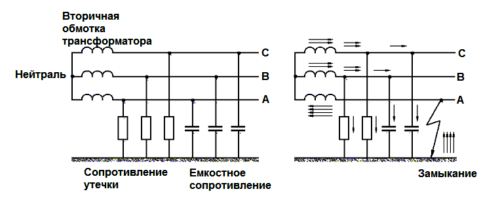
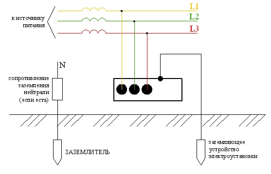
A network with an isolated neutral is a replacement circuit, taking into account the specific electrical capacity of the network and the insulation resistance. This is shown in the figure.
Such circuit components create a leakage current. At various conditions in such networks of 380 volts, the leakage current is negligible, and amounts to a few milliamps. Despite this, such a short circuit leads to a network failure, although the network may still work for some time.
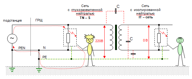
We must not forget that in similar networks, when the 1-phase is closed to the ground, the voltage between the ground and the serviceable phases increases significantly. This voltage approaches 380 volts (line voltage). This fact may lead to electric shock electrical workers.
Also, an isolated neutral, when one phase is shorted to ground, contributes to the breakdown of insulation and the appearance of a short circuit on other phases, that is, an interphase short circuit can occur with high currents. To provide protection in such a situation, fuse links or circuit breakers are needed.
A double ground fault is very dangerous for network workers. Therefore, if there is a single-phase short circuit in the network, then such a network is considered emergency, since the safety conditions are sharply reduced. The presence of "ground" increases the risk of electric shock when touching live parts. Therefore, short circuits of even one phase to earth must be immediately eliminated.
The insignificant value of the 1-phase fault current with an isolated neutral is the reason for such a factor that such a fault cannot be disconnected and. Therefore, auxiliary relay electrical installations will be required that will warn of emergency operation.
This power system requires a significant number of alarms and protective devices, and high qualification requirements are imposed on the workers who serve the networks.
Advantages
Isolated neutral mode has the advantage of not needing to promptly trip the first 1-phase ground fault. A small current appears at the fault points, provided small capacity current to ground.
This mode is used to a limited extent, as it has several serious drawbacks.
Flaws
- Difficult troubleshooting.
- All electrical installations must be isolated to line voltage.
- If the circuit continues for a long time, then there is a real danger of electric shock to a person.
- With 1-phase short circuits, the normal functioning of relay protection is not ensured, since the value of the actual fault current directly depends on the operation of the power supply network, namely on the number of connected circuit branches.
- The service life of insulation is reduced due to the gradual accumulation of defects due to exposure to arc overvoltages for a long time.
- Damage may appear in various places due to insulation breakdown in other places where arc overvoltages appear. Therefore, many cables fail, just like electric motors and other electrical installations.
- Arc surges, low current arcs may occur in places of a 1-phase ground fault.
As a result, it can be said that a significant number of disadvantages outweigh all the advantages of this grounding mode. But under certain conditions, this method fully shows its effectiveness and does not violate the requirements of the rules of electrical installations.
It is known that in cable and overhead lines nutrition transformer substations there are high voltages, during the transmission of which it is especially important to observe safety precautions. Like 380 Volt power supply systems, high-voltage lines (VL) are switched on according to schemes that provide effective protection from damage by voltages acting in the circuit. At the same time, in accordance with PUE requirements the neutral point of the supply transformer (neutral) is most often reliably grounded, that is, it is connected to a grounding device specially equipped for this purpose - a charger.
Ways to turn on the neutral
The specifics of the operation of high-voltage (HV) systems is that in the event of a break or damage to the line, accompanied by a short circuit separate wire ground, leakage currents can be very high. Accordingly, the protective measures taken in such networks are markedly different from those in end-user circuits.
For networks of 6-35 kilovolts, the neutral grounding modes listed below are typical:
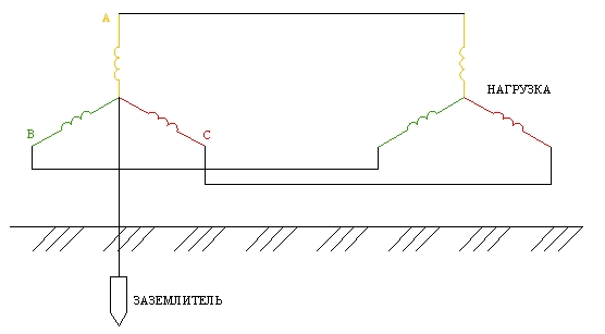
- direct connection to the charger, equipped directly at the substation or at the high-voltage pole (solidly grounded ground neutral);
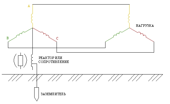
- connection through a special arcing reactor or compensator;
- the use of a grounding system for these purposes, in which the neutral is connected through a resistor;
- without connection to the charger within the boundaries of the protected line or object (isolated neutral).
The installation of special compensating elements in the neutral conductor connection circuit helps to reduce the capacitive components of the short circuit currents. During the operation of such a circuit, these currents can be neutralized due to a smooth change in the inductance of the coil, the voltage in which has a reverse phase.
At a certain value, the inductance drops to zero. To improve the efficiency of such grounding, a resistor is connected in parallel with the inductance, which provides conditions for the flow of the active component of the current used to operate the high-voltage protection relay. Other options for switching on the neutral will be discussed separately below.
Each of these schemes requires a mandatory device on the receiving side of a separate charger that provides re-grounding of the neutral and creates safe conditions VL operation.
Without this device, the switching circuits used cannot effectively fulfill their protective functions, because in the event of an accidental break in the neutral conductor, the power equipment of substations will remain unprotected.
Another option is possible, in which the neutral grounding in 6-35 kV networks is carried out through the inclusion common point into the supply network, called effective grounding and implemented through the creation of practically ideal conditions to drain current to ground. However, it is considered too expensive and is usually used only at supply substations with input voltages of 110 kilovolts and above.
Systems with isolated neutral from earth
The mode of operation of networks with an isolated neutral is quite common in most regions of Russia. With this method of connection, the neutral point of the supply generator (transformer) with the arrangement of the windings according to the "triangle" scheme remains ungrounded.
The reason for the demand for the option under consideration is that with this neutral connection scheme, any phase-to-ground short circuit cannot be considered short (due to the lack of communication through the ground). Moreover, in such an emergency mode, the high-voltage network can operate without much damage for several hours.
Other advantages of this circuit include low currents at the point of one-phase-to-earth fault (OSZ) due to the insignificant capacitance of the network relative to the ground.
Important! Surge currents at this option switching on is much less than in the case of phase-to-phase faults, which is another advantage of these networks.
In this regard, such systems do not need special fast-acting means of protection against SPE, which significantly reduces the cost of their operation.
To the number significant shortcomings such a connection should include:
- the possibility of overvoltage formation with arc effects and relatively small currents (up to tens of amperes) at the point of SPZ;
- the associated possibility of damage to cable or high-voltage equipment due to the destruction of insulation due to arc overvoltages;
- the requirement to take into account the increased (linear 380 Volts) voltage, if necessary, to reliably isolate the linear electrical equipment;
- difficulty in identifying exact location damage.
Thus, before choosing this method of connecting the neutral, all the pros and cons must be taken into account, as well as calculated possible consequences emergency modes.
through low resistance
Grounding the neutral with a small nominal resistor is widely practiced in only a few countries (in Russia and Belarus, in particular). At the same time, it seems more logical to use a high-resistance resistor (RB-mode) in these circuits, which provides a low level of overvoltages in the SFG mode.
Other types of neutral grounding involve the use of combined options for its connection using inductance (LB plus RB modes).
But upon careful study of these approaches, it turns out that high-resistance resistors differ not only in significant dimensions, but also have a decent weight and cost. The variant of the installation of arc-quenching reactors considered above also has its own characteristics and disadvantages characteristic of it.
As a result, before choosing a mode with a low-resistance resistor, comprehensive studies and calculations should be carried out, taking into account all the above factors.
 There are two known ways to implement low-resistance grounding, one of which involves the installation of a resistive element in these circuits, which ensures the operation of current protection in the event of a fault. The second approach uses inductance-grounded circuits designed to protect against double phase faults.
The resistive version takes into account additional current components in the neutral, exceeding capacitive values OZZ approximately 3 or more times. In circuits with reactive (inductive) grounding, the level of these components should not exceed the sum of the operating currents from double circuits and capacitive short circuit at SPE.
We also note that according to the PUE, the operating modes under consideration are usually divided into short-term and long-term. In the latter case, the grounding elements are permanently placed in the neutral connection chain. The use of this connection method in accordance with safety requirements is allowed only with sufficiently high-quality grounding (RЗ ≤ 0.5 Ohm), which is inappropriate both for economic reasons and for labor costs.
 (1 ratings, on average: 5,00 out of 5)

