Electrical circuit for switching on a single-phase electric motor. Single-phase asynchronous
Hello, dear readers and guests of the Electrician's Notes website.
I am often asked how one can distinguish the working winding from the starting winding in single-phase motors when there are no markings on the wires.
Each time you have to explain in detail what and how. And today I decided to write a whole article about this.
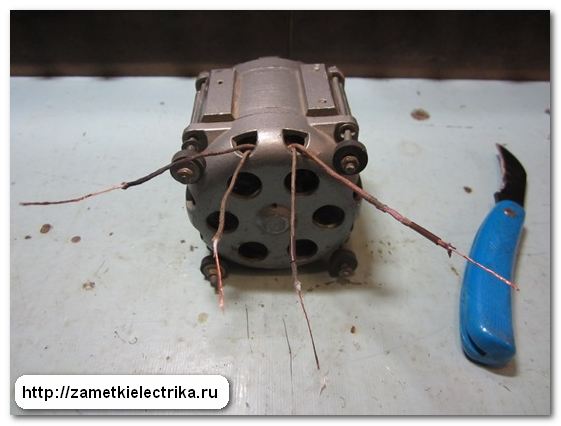
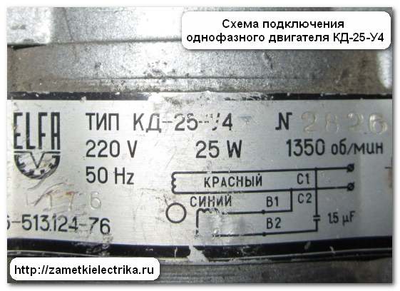
As an example, I’ll take a single-phase electric motor KD-25-U4, 220 (V), 1350 (rpm):
- KD - capacitor motor
- 25 - power 25 (W)
- U4 - climatic version
Here is his appearance.


As you can see, there are no markings (color and numbers) on the wires. On the engine tag you can see what markings the wires should have:
- working (C1-C2) - red wires
- starting (B1-B2) - blue wires
![]()
First of all, I will show you how to determine the working and starting windings of a single-phase motor, and then I will assemble a circuit diagram for its connection. But this will be the subject of the next article. Before you start reading this article, I recommend that you read: connecting a single-phase capacitor motor.
So let's get started.
1. Wire cross-section
Visually check the cross-section of the conductors. A pair of wires with a larger cross-section belong to the working winding. And vice versa. Wires with a smaller cross-section are classified as starting wires.
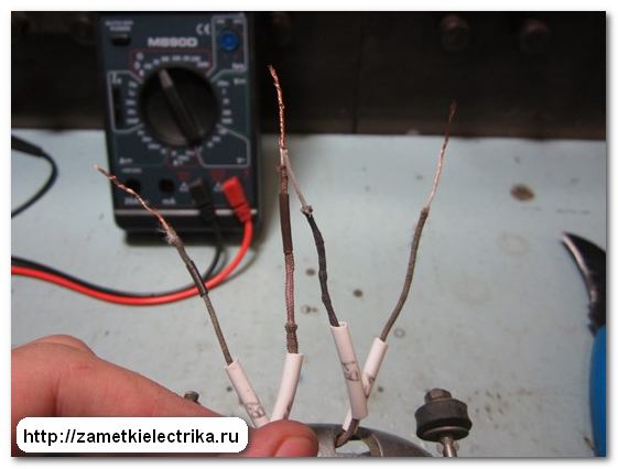
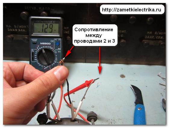
Then we take the multimeter probes and measure the resistance between any two wires.
![]()
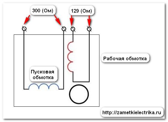
If there is no reading on the display, then you need to take another wire and measure again. Now the measured resistance value is 300 (ohms).

We found the conclusions of one winding. Now we connect the multimeter probes to the remaining pair of wires and measure the second winding. It turned out to be 129 (Ohm).

We conclude: the first winding is the starting winding, the second is the working winding.
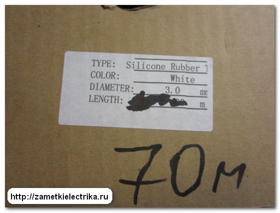
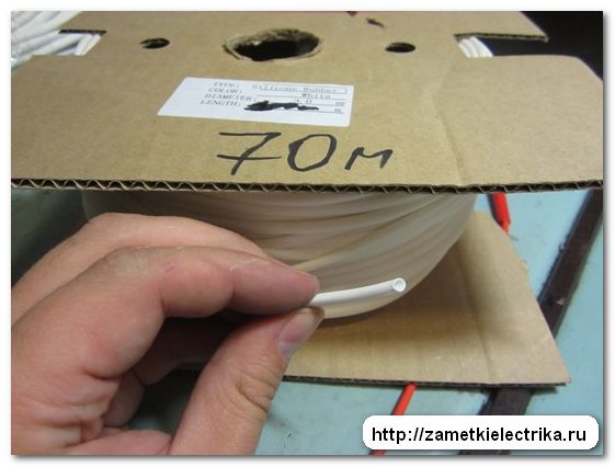
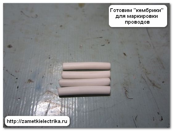
In order not to get confused in the wires when connecting the motor in the future, we will prepare tags (“cambrides”) for marking. Usually, as tags I use either loom PVC or silicone tube (Silicone Rubber) of the diameter I need. In this example, I used a silicone tube with a diameter of 3 (mm).
According to new GOSTs, the windings of a single-phase motor are designated as follows:
- (U1-U2) - working
- (Z1-Z2) - launcher
The KD-25-U4 engine, taken as an example, digital marking done the same way:
- (C1-C2) - working
- (B1-B2) - launcher
To avoid any discrepancies between the wire markings and the diagram shown on the engine tag, I left the old markings.
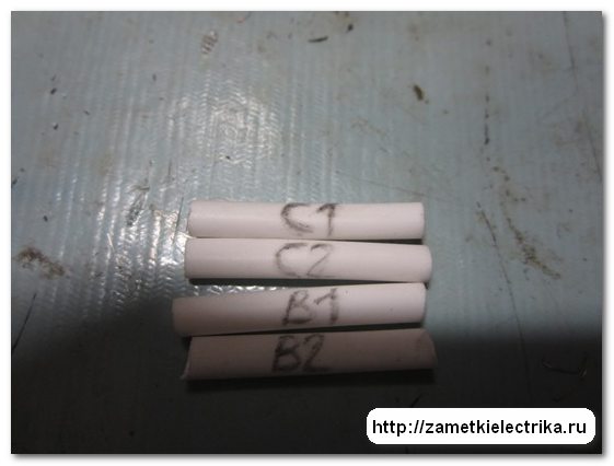
I put tags on the wires. This is what happened.


For reference: Many people are mistaken when they say that the rotation of the motor can be changed by rearranging the power plug (changing the poles of the supply voltage). It is not right!!! To change the direction of rotation, you need to swap the ends of the starting or working windings. The only way!!!
We considered the case when 4 wires are connected to the terminal block of a single-phase motor. And it also happens that only 3 wires are connected to the terminal block.
In this case, the working and starting windings are connected not in the terminal block of the electric motor, but inside its housing.
What to do in this case?
We do everything the same way. We measure the resistance between each wire. Let's mentally label them as 1, 2 and 3.

![]()
Here's what I got:
- (1-2) - 301 (Ohm)
- (1-3) - 431 (Ohm)
- (2-3) - 129 (Ohm)

From this we draw the following conclusion:
- (1-2) - starting winding
- (2-3) - working winding
- (1-3) - starting and working windings are connected in series (301 + 129 = 431 Ohm)
For reference: With this connection of the windings, reversing a single-phase motor is also possible. If you really want, you can open the motor housing, find the junction of the starting and working windings, disconnect this connection and bring out 4 wires into the terminal block, as in the first case. But if your single-phase motor is capacitor-based, as in my case with KD-25, then it
Often the focus is on studying three-phase electric motors, partly due to the fact that three-phase electric motors are used more often than single-phase electric motors. Single-phase electric motors have the same operating principle as three-phase electric motors, only with lower starting torques. They are divided into types depending on the starting method.
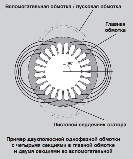
A standard single-phase stator has two windings located at an angle of 90° to each other. One of them is considered the main winding, the other is the auxiliary or starting winding. In accordance with the number of poles, each winding can be divided into several sections.
The figure shows an example of a two-pole single-phase winding with four sections in the main winding and two sections in the auxiliary winding.
It should be remembered that the use single-phase electric motor- it is always a kind of compromise. The design of a particular engine depends, first of all, on the task at hand. This means that all electric motors are designed according to what is most important in each specific case: e.g. efficiency, torque, duty cycle, etc. Due to the pulsating field, single-phase CSIR and RSIR motors may have more high level noise compared to two-phase electric motors PSC and CSCR, which are much quieter because they use a starting capacitor. The capacitor through which the electric motor is started contributes to its smooth operation.
Main types of single-phase induction motors
Household appliances and low power devices operate on single-phase alternating current In addition, three-phase power supply cannot be provided everywhere. Therefore, single-phase AC motors have become widespread, especially in the USA. Very often, AC motors are preferred due to their robust design, low cost, and they also require no maintenance.
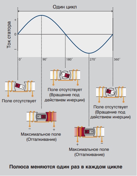
As the name suggests, a single-phase induction motor operates on the principle of induction; the same principle applies to three-phase electric motors. However, there are differences between them: single-phase electric motors, as a rule, operate at alternating current and voltage 110 -240 V, the stator field of these motors does not rotate. Instead, each time the sinusoidal voltage jumps from negative to positive, the poles change.
In single-phase electric motors, the stator field is constantly aligned in one direction, and the poles change their position once in each cycle. This means that a single-phase induction motor cannot be started on its own.
In theory, a single-phase electric motor could be started by mechanically rotating the motor and then immediately applying power. However, in practice, all electric motors start automatically.
There are four main types of electric motors:
Induction motor with capacitor start / winding operation (inductance) (CSIR),
Capacitor start/capacitor run (CSCR) induction motor
Rheostat starting induction motor (RSIR) and
Permanent Split Capacity (PSC) motor.
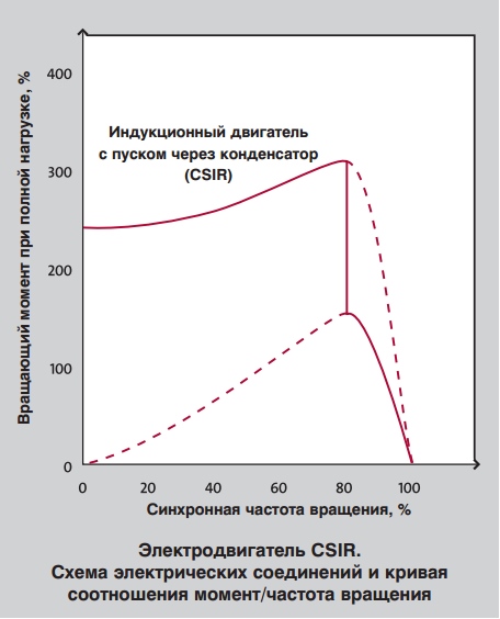
The figure below shows typical torque/speed curves for the four main types of single-phase AC motors.

Single-phase capacitor-start/inductive-run (CSIR) motor
Capacitor start induction motors, also known as CSIR motors, form the largest group of single-phase electric motors.
CSIR motors are available in several sizes: from the lowest power to 1.1 kW. In CSIR motors, the capacitor is connected in series with the starting winding. The capacitor causes some lag between the current in the starting winding and the current in the main winding.
![]()
This contributes to a delay in the magnetization of the starting winding, which leads to the appearance of a rotating field, which affects the occurrence of torque. After the electric motor picks up speed and approaches the operating speed, the starter opens. Next, the electric motor will operate in the usual mode for an induction electric motor. The starter can be centrifugal or electronic.
CSIR engines have a relatively high Starting torque, ranging from 50 to 250 percent of full load torque. Therefore, of all single-phase electric motors, these motors are best suited for applications where starting loads are high, such as conveyors, air compressors and refrigeration compressors.
Single-phase capacitor start/capacitor run (CSCR) motor
This type of motor, called CSCR motor for short, combines best properties an induction motor with a capacitor start and a motor with a permanently connected capacitor. Although these motors are somewhat more expensive than other single-phase electric motors due to their design, they remain the best option for use in difficult conditions. The starting capacitor of the CSCR electric motor is connected in series with the starting winding, as in a capacitor starting electric motor. This provides high starting torque.
CSCR motors are also similar to permanent split capacitance (PSC) motors in that they also start via a capacitor, which is connected in series with the starting winding if the starting capacitor is disconnected from the mains. This means that the engine is coping with maximum load or overload.
CSCR motors can be used to operate at low full load current and at higher efficiency. This offers several benefits, including allowing the motor to operate with less temperature fluctuations than other similar single-phase motors.
CSCR electric motors are the most powerful single-phase electric motors that can be used in difficult conditions, for example, in pumps for pumping water under high pressure and in vacuum pumps, as well as in other high-torque processes. The output power of such electric motors ranges from 1.1 to 11 kW.

Single-phase resistive start/inductance run (RSIR) motor
This type of motor is also known as “split-phase electric motor”. They are generally cheaper than other types of single-phase electric motors used in industry, but they also have some performance limitations.
The RSIR motor starter includes two separate stator windings. One of them is used exclusively for starting; the wire diameter of this winding is smaller, and electrical resistance- higher than that of the main windings. This causes a lag in the rotating field, which in turn drives the motor. A centrifugal or electronic starter disconnects the starting winding when the engine speed reaches approximately 75% of the rated speed. The motor will then continue to operate according to standard induction motor operating principles.
As mentioned earlier, there are some limitations to RSIR motors. They have low starting torques, often in the range of 50 to 150 percent of rated load. In addition, the electric motor produces high starting currents, approximately 700 to 1000% of rated current. As a result, a long starting time will cause overheating and destruction of the starting winding. This means that electric motors of this type cannot be used where large starting torques are required.
RSIR electric motors are designed for a narrow supply voltage range, which naturally limits their applications. Their maximum torques vary from 100 to 250% of the design value. It should also be noted that an additional difficulty is the installation of thermal protection, since it is quite difficult to find protective device, which would operate quickly enough to prevent the starting winding from burning out. RSIR motors are suitable for use in small chopping and grinding applications, fans and other applications where low starting torque and shaft power requirements of 0.06 kW to 0.25 kW are acceptable. They are not used where high torques or long cycles are required.

Single-phase permanent split capacitance (PSC) motor
As the name suggests, permanent split capacitance (PSC) motors are equipped with a capacitor that is constantly on during operation and connected in series with the starting winding. This means that these motors do not have a starter or capacitor that is used only for starting. Thus, the starting winding becomes an auxiliary winding when the motor reaches operating frequency rotation.

PSC motors are designed such that they cannot provide the same starting torque as motors with starting capacitors. Their starting torques are quite low: 30-90% of the rated load, so they are not used in systems with a large starting load. This is compensated by low starting currents - typically less than 200% of rated load current - making them the most suitable motor for long duty cycle applications.
Motors with permanent capacity division have a number of advantages. The operating parameters and speed of such motors can be adjusted to suit the application, and they can be manufactured for optimum efficiency and high power factor at rated load. Since they do not require a special starting device, they can be easily reversed (change the direction of rotation to the opposite). In addition to all of the above, they are the most reliable of all single-phase electric motors. That's why Grundfos uses single-phase PSC motors as standard for all applications with powers up to 2.2 kW (2-pole) or 1.5 kW (4-pole).
Continuously split capacity motors can be used for a number of different applications depending on their design. A typical example is low inertia loads such as fans and pumps.

Two-wire single-phase electric motors
Two-wire single-phase electric motors have two main windings, a starting winding and a run capacitor. They are widely used in the US with single phase power supplies: 1 ½ 115 V / 60 Hz or 1 ½ 230 V / 60 Hz. At correct connection This type of electric motor can be used for both types of power supply.

Limitations of single-phase electric motors
Unlike three-phase motors, there are some restrictions for single-phase electric motors. Single-phase electric motors should never be operated in idle mode, as they become very hot at low loads, and it is also recommended to operate the motor at a load less than 25% of the full load.
PSC and CSCR motors have a symmetrical/circular rotating field at one load point; this means that at all other points of load application the rotating field is asymmetrical/elliptical. When an electric motor operates with an asymmetric rotating field, the current in one or both windings may exceed the line current. Such excess currents cause losses, and therefore one or both windings (which often occurs when there is no load at all) heat up, even if the current in the network is relatively small. See examples.


About voltage in single-phase electric motors
It is important to remember that the voltage on the starting winding of the electric motor may be higher than the mains supply voltage of the electric motor. This also applies to symmetrical mode work. See example.

Changing the supply voltage
It should be noted that single-phase electric motors are usually not used for large voltage ranges, unlike three-phase electric motors. In this regard, there may be a need for motors that can operate with other types of voltage. To do this, it is necessary to make some design changes, for example, you need additional winding and capacitors various capacities. Theoretically, the capacitance of the capacitor for different mains voltages (with the same frequency) should be equal to the square of the voltage ratio:
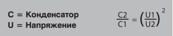
Thus, in an electric motor designed to be powered from a 230 V network, a 25 µF/400 V capacitor is used; for a 115 V electric motor model, a 100 µF capacitor is required with a lower voltage marking - for example, 200 V.
Sometimes capacitors of smaller capacity are chosen, for example 60µF. They are cheaper and take up less space. In such cases, the winding must be suitable for the specific capacitor. It must be taken into account that the performance of the electric motor will be less than with a capacitor with a capacity of 100 µF - for example, the starting torque will be lower.
Conclusion
Single-phase electric motors operate on the same principle as three-phase ones. However, they have lower starting torques and supply voltages (110-240V).
Single-phase electric motors should not be run at idle, and many should not be operated at less than 25% of maximum load, as this causes the temperature inside the motor to rise, which can lead to motor failure.
Today we will look at connecting a single-phase AC motor. These include asynchronous and synchronous motors powered by a single phase, which usually has a voltage of 220 Volts. They are very common in the domestic sphere and small-scale production, private entrepreneurship.
To accelerate an asynchronous motor, it is necessary to create a rotating magnetic field. This is easily handled by a three-phase power supply, where the phases are shifted relative to each other by 120 degrees. But if we are talking about how to connect a single-phase electric motor, then a problem arises: without a phase shift, the shaft will not begin to rotate.
Inside a single-phase asynchronous motor there are two windings: starting and working. If a phase shift is provided in them, the magnetic field will become rotating. And this is the main condition for starting the electric motor. The phases can be shifted by adding resistance (resistor) or an inductive coil. But the most commonly used capacitors are starting and/or running capacitors.
With starting capacity
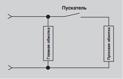
In most cases, the circuit only includes a starting capacitor. It is active only when the engine is starting. Therefore, the method is good when the launch promises to be difficult, otherwise the shaft will not be able to accelerate due to the small initial torque. After acceleration, the starting capacitor is turned off and operation continues without it.
The connection diagram for a motor with an auxiliary tank is shown in the figure above. To implement it, you will need a relay or at least one button, which you will press for 3 seconds while starting the motor. The auxiliary capacitor, together with the auxiliary winding, is included in the circuit only for a while.
This arrangement provides optimal starting torque if minor AC surges occur during startup. But there is also a drawback - when operating in nominal mode specifications fall. This is due to the shape of the magnetic field of the working winding: it is oval, not circular.
With working capacity
If the start is easy, but the work is hard, then instead of a starting capacitor you will need a working capacitor. The connection diagram is shown below. The peculiarity is that the working capacitance, together with the working winding, is constantly connected to the circuit.

The scheme provides good characteristics when operating in nominal mode.
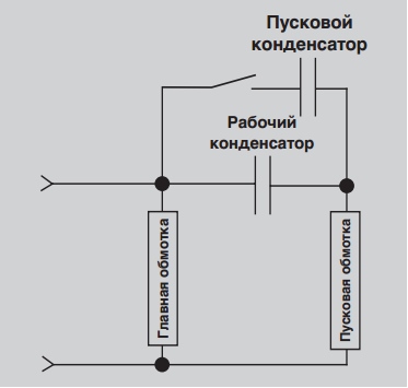
With both capacitors
A compromise solution is the use of auxiliary and working capacity simultaneously. This method is ideal if the AC motor is already started with a load, and the work itself is difficult for it. Look, the diagram below is like two diagrams (with working and auxiliary capacitance) superimposed on each other. When starting, the trigger will be turned on for a few seconds, and the second drive will be active all the time: from start to shutdown.

Capacity calculation
The greatest difficulty for beginners is calculating the capacitance of capacitors. Professionals select them empirically, listening to the engine during startup and operation. This is how they determine whether the drive is suitable or whether they need to look for another one. But with a small error in most cases, the capacity can be calculated as follows:
- For a working drive: 0.7-0.8 µF per 1000 watts of electric motor power;
- For the starting capacitor: 2.5 times more.
Example: you have a 2 kW asynchronous single-phase electric motor. This is 2000 watts. This means that when connecting with working capacity you need to stock up on a 1.4-1.6 uF drive. For the starting one you will need 3.5-4 uF.
Connecting a single-phase synchronous electric motor
Despite the complexity of the design of synchronous motors, they have many advantages over asynchronous ones. The main thing is the low sensitivity to voltage surges leading to a sharp decrease or increase in current. No less significant is the fact that synchronous motors can operate even with overload, not to mention optimal mode reactive energy and shaft rotation with constant speed. However, connecting is a labor-intensive process, and this is already a disadvantage.
Overclocking method
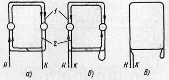
You cannot start a single-phase synchronous motor by simply applying power to its windings. Because at the moment of switching on, the direction of the supply current in the stator windings corresponds to figure (a). At this time, a pair of forces acts on the rotor, which is still at rest, which will try to rotate the shaft clockwise. But after half the period in the stator windings, the current will change its direction. Therefore, a pair of forces will already act in the opposite direction, turning the shaft counterclockwise, as in figure (b). Since the rotor has great inertia, it will never move.

To make the rotor rotate, it is necessary that it has time to make at least half a revolution so that a change in the direction of the current does not affect its rotation. This is possible if the shaft is accelerated with the help of outside forces. This can be done in two ways:
- Manually;
- Using a second engine.
Only low-power synchronous electric motors can be accelerated with your own hand strength. And for medium- and high-power units you will have to use a different motor.
When accelerating with an external force, the rotor begins to rotate at a speed close to synchronous. Then only the excitation winding turns on, and then the stator winding.
Asynchronous start of a synchronous motor
If metal rods are placed in the tips on the rotor poles, and they are connected to each other on the sides by rings, then the motor must be started asynchronously. These rods play the role of an auxiliary winding that an asynchronous motor has. In this case, the excitation winding is short-circuited using a discharge resistor, and the stator winding is connected to the network. This is the only way to ensure the same overclocking as asynchronous electric motor. But after the rotation speed is as close as possible to synchronous (95% of it is enough), the excitation winding is connected to the source direct current. The speed becomes completely synchronous, which entails a decrease in the induced emf of the auxiliary winding down to zero. And it turns off automatically.
26. WINDING DIAGRAMS OF SINGLE-PHASE INDUCTION MOTORS
In single-phase motors with a starting winding, the main winding usually occupies 2/3 and the auxiliary winding occupies 1/3 of the total number of stator slots. In these motors, the number of slots per pole for each phase is determined by the formulas:
Where q A - number of slots per main phase pole; q V- number of slots per pole of the auxiliary phase; z A = 2/3 - number of slots occupied by the main phase; z B= 1 / 3 - number of slots occupied by the auxiliary phase; z- total number of grooves; 2p- number of poles.
In single-phase capacitor motors, the stator slots are usually divided equally between both phases, i.e. z A=z B, and the number of slots per pole is determined by the formula
The slot pitch for single-phase windings is determined in the same way as for three-phase windings. Double-layer windings are made with shortening, usually by 1/3 pole division, with equal steps for the main and auxiliary windings. Double layer winding pitch
The connection of coil groups and the formation of parallel branches in single-phase windings is carried out according to the same rules as for three-phase windings.
When constructing motor circuits with increased resistance of the starting phase, it is necessary to take into account the presence of a bifilar winding in it.
For ease of repair, the starting winding is usually placed on top of the main winding (closer to the wedge).
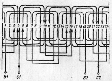
An approximate procedure for drawing up a diagram of a single-phase motor winding with a starting element. We will analyze the sequence of drawing up a single-layer winding circuit using an example
2p = 4, z = 24.
First, find the number of slots occupied by the main phase,
Number of slots per main phase pole
The number of slots per pole of the auxiliary phase is half that of the main phase, i.e.
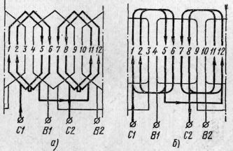
Next in the drawing you need to present the sequence of alternating grooves of the main and auxiliary phases (Fig. 60, A) and indicate the direction of the current in the main phase, based on the rules: under adjacent poles the direction of the current changes to the opposite (Fig. 60, b). To prevent the main phase coil from being cut in the diagram when performing the most common type of waddling winding, the first coil group is divided into two halves (grooves 1,2 and 23,24).
In accordance with the indicated direction of the current, the grooved parts of the coils are connected, as a result of which coil groups or semi-groups are formed. In this case, it is possible various options. With diametrical pitch
the same for all coils, a simple template winding is obtained (Fig. 60, V), the number of coil groups of which is equal to the number of pole pairs R. But such a winding is almost never used due to large sizes frontal parts. If we divide each coil group into two semi-groups, we get a template winding waddle (Fig. 60, G) with smaller pitch and shorter coil length. However, due to the large compactness of the frontal parts, a concentric waddling winding is more often used (Fig. 60.5). At large values qA A concentric winding is also used, in which the coil group is divided into three semi-groups (see Fig. 68). In terms of the appearance of the frontal parts, this winding resembles a three-plane three-phase concentric winding.
The beginning of the phase can, in principle, be selected from any slot, based on the convenience of the winding. Starting bypassing all the grooves from the first groove and monitoring the direction of the current, we connect the coil groups (semi-groups) to each other (Fig. 60, e) and babysit
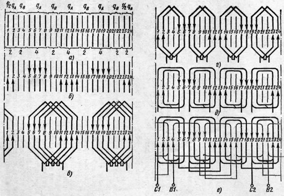
Rice. 60. Construction of a single-layer winding circuit for a single-phase motor with a starting element: a - sequence of alternating slots of the main and auxiliary phases. b - direction of current in the grooved parts of the main phase coils, c - simple template winding, d - template waddle winding, e - concentric waddle winding, f - diagram of the main and auxiliary phases of the concentric waddle winding
phase, bypassing all the slots of the working winding. The connection of semigroups is made according to the rule: the end of the semigroup is connected to the end of the adjacent semigroup of the same phase, the beginning - to the beginning, i.e., the same as in a three-phase single-layer winding, where the coil group is divided into two semigroups.
Rice. 61. Single-layer waddle windings single phase motors at 2p=2, z=12: a - template, b - concentric
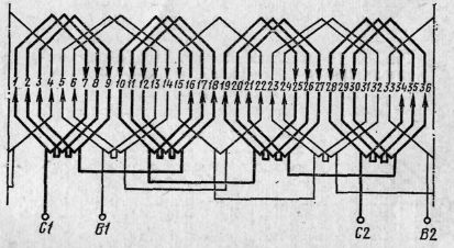
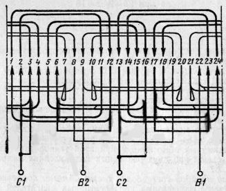
Rice. 62. Single-layer (template waddle) winding of a single-phase motor at 2р=4, z=36
The auxiliary phase circuit follows the same rules, only it usually has a smaller number of coils in a group (semi-group). Its step may be the same as that of the main phase or different.
Typical diagrams of single-layer motor windings with starting elements are shown in Fig. 61.62.
The diagram of a two-layer motor winding with a starting element can be drawn up in the following sequence. First determine the step
windings, number of slots per pole for main and auxiliary phases qA And qB. In accordance with the winding pitch and the number of coils in the group, equal to q A , the first coil group of the main phase is drawn (Fig. 63, 64), next to it is the coil group of the auxiliary phase, then again the coil group of the main phase, etc. The steps along the grooves for both phases are taken the same. The direction of the current is indicated in the upper sides of the main phase coils (under adjacent poles it changes to the opposite, as in one
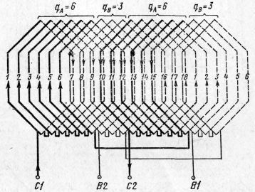
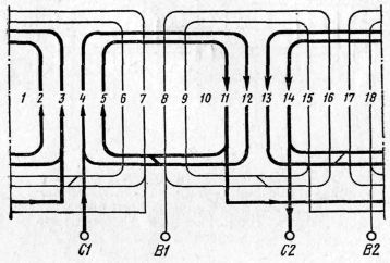
Rice. 63. Double-layer winding of a single-phase motor at 2р=2, z=18, q A = 6, q B = 3, y A =y B =6(1-7)
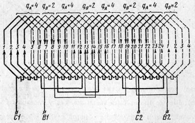
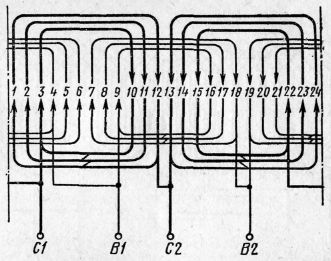
Rice. 64. Double-layer winding of a single-phase motor at 2p=4, z=24, q A =4, q B =2, y A =y B =4(1-5)
layer winding). Serial connection coil groups in phase are also fulfilled according to the rule: end with end, beginning with beginning, in this case the polarity of the poles will not be violated. Connections in the auxiliary phase are made in a similar way.
An approximate procedure for drawing up a diagram of a single-phase single-layer motor winding with increased resistance of the auxiliary phase. Diagram of the main phase of a motor with increased resistance
Rice. 65. Execution of a coil with a bifilar winding: a - a coil divided into two sections, b - a coil with a bifilar winding, c - designation of a coil with a bifilar winding in the diagram; 1 - main section, 2 - bifilar section, H and K - beginning and end of the coil
The auxiliary phase is the same as for motors with starting elements.
When drawing up a diagram of the auxiliary phase, it must be taken into account that in each coil some of its turns are wound counter-wound. This reduces the number of effective conductors in the slot. Counter-wound turns neutralize the effect of the same number of turns wound in the main direction, forming a bifilar winding, therefore, to find the number of effective turns in the coil (effective conductors in the slot), it is necessary to subtract twice the number of counter-wound turns from the total number. If, for example, there is a coil in the groove with only 81 turns, 22 of which are counter-wound, then the number of effective conductors in the groove will be: 81-2x22=37.
To determine the number of counter-wound turns with a known total number of conductors in the slot and the number of effective conductors in the slot, it is necessary to perform the reverse action, i.e., subtract the number of effective conductors from the total number and divide the resulting result by two. With a total number of conductors of 81 and an effective number of 37, the number of counter-wound turns should be:
A coil with a bifilar winding can be obtained by placing two coil sections in the same slots, one of which rotates 180° around an axis parallel to the slots. The right and left sides of the rotated section are swapped (Fig. 65). In the grooves where the coil with the bifilar winding is located, the current
Rice. 66. Single-layer concentric waddling winding at 2p=4, z=24 of a single-phase motor with increased resistance of the auxiliary winding: a - a coil with a bifilar winding is shown in the form of two sections, b - the same, in the form of a whole coil
Rice. 67. Single-layer concentric waddling winding at 2p=2, z=18 of a single-phase motor with increased resistance of the auxiliary phase: a - when wound counterclockwise, b - when wound clockwise
Rice. 68. Single-layer concentric winding with a coil group divided into three parts at 2р=2, z=24 of a single-phase motor with increased resistance of the auxiliary phase
Rice. 69. Single-layer concentric winding with a coil group divided into three parts at 2р=2, z=24 of a single-phase motor with increased resistance of the auxiliary phase and connection of the main phase into two parallel branches
passes along one section in the same direction, along the other - in the opposite direction. The polarity of the poles is determined by the direction of the current in the coil with a large number of turns, therefore the section with a large number of turns is conventionally called the main one, and with a smaller number - bifilar.
In Fig. 66, A a circuit with a bifilar winding in the auxiliary phase is presented; the bifilar section is conventionally shown inside the main one. Typically, coils with bifilar windings in the diagrams are
Rice. 70. Single-layer concentric winding of a single-phase capacitor motor at 2р=2, z=18
appear in the form of a whole coil with a loop in which the direction of the current changes (Fig. 65, V and rice 66, b).
Coils and coil groups with bifilar windings must be connected in such a way that the polarity under adjacent poles of the auxiliary phase alternates; The polarity of the poles is determined by the direction of the current in the main sections.
Typical circuits of motor windings with increased resistance of the auxiliary phase are shown in Fig. 67-69.
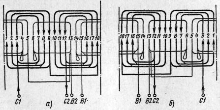
Any winding can be wound either clockwise or counterclockwise when looking at the stator from the circuit side. This is determined by the skills of the wrapper and the manufacturing technology adopted. An example of a circuit with two different winding directions is shown in Fig. 67.
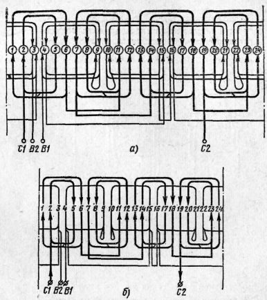
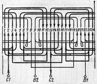
An approximate procedure for drawing up a winding diagram for a capacitor motor. Single-phase capacitor motor circuits are constructed in the same way as single-phase circuits with starting elements, only it must be taken into account that the number of slots per pole of the main and auxiliary phases are the same and therefore the circuits of both phases are also the same.
Typical circuits of single-phase capacitor motors are shown in Fig. 70-76.
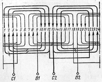
Rice. 71. Single-layer concentric winding of a single-phase capacitor motor at 2р=2, z=24
Rice. 72. Single-layer concentric winding of a single-phase capacitor motor at 2р=2, z=24 and connecting each of the phases into two parallel branches
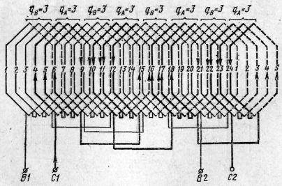
Rice. 73. Single-layer concentric winding with “combed” coils of a single-phase capacitor motor at 2p=4, z=24
Rice. 74. Double-layer winding of a single-phase capacitor motor at 2p=4, z=24, q A =q B =3, y A =y B =5(1-6)
In some cases, capacitor motors are characterized by the presence of “combed” coils with half the number of turns in both phases. In the diagram fig. Figure 73 shows four such coils.
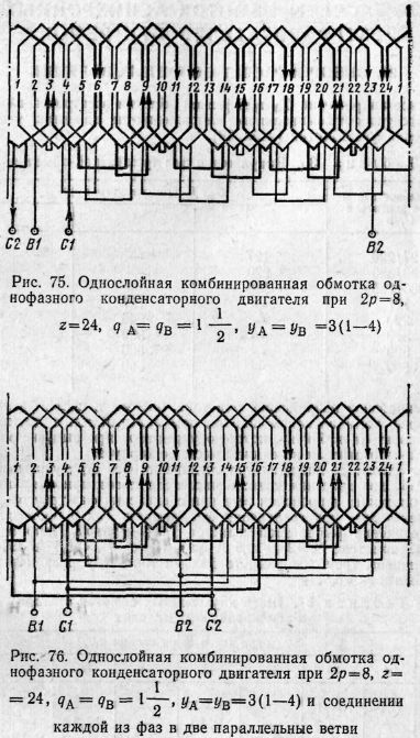
The winding shown in Fig. 75, 76, due to the fractional number of slots per pole, has the characteristics of a template waddling and two-layer windings and is therefore called combined.
§ 96. Single-phase asynchronous motors
Single-phase asynchronous motors are widely used at low powers (up to 1 - 2 kW). This engine is different from a regular one. three phase motor because it fits on the stator single phase winding. Therefore, any three-phase asynchronous motor can be used as single-phase. The rotor of a single-phase asynchronous motor can have a phase or short-circuited winding.
A feature of single-phase asynchronous motors is the absence of an initial or starting torque, i.e., when such a motor is connected to the network, its rotor remains motionless.
If, under the influence of some external force, the rotor is brought out of rest, the engine will develop torque.
The absence of an initial moment is significant drawback single-phase asynchronous motors. Therefore, these motors are always equipped with a starting device.
To obtain the initial torque, you can place two windings on the stator, shifted one relative to the other by half a pole pitch (90°). These windings must be connected to a symmetrical two-phase network, that is, the voltages applied to the windings of the coils must be equal to each other and shifted by a quarter of a period in phase.
In this case, the currents flowing through the coils will also be out of phase by a quarter of a period, which, in addition to the spatial shift of the coils, makes it possible to obtain a rotating magnetic field. In the presence of a rotating magnetic field, the motor develops a starting torque.
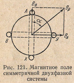
The simplest two-phase winding can be represented in the form of two coils (Fig. 121), the axes of which are shifted in space by 90°. If on these coils having same number turns, skip equal in magnitude and shifted in phase by a quarter of the period sinusoidal currents, i.e.
That magnetic fields these coils will also be sinusoidal and shifted in phase by a quarter of the period, i.e.
In this case, the vector IN A directed along the axis of the coil A - X, and the vector IN B- along the axis of the coil B - Y.
At any moment, the resulting magnetic field is equal to the geometric sum of the magnetic fields of the coils A And IN, i.e.
Consequently, with such a device, the resulting magnetic field of a two-phase winding has a constant value equal to the amplitude of the field of one phase.
Since magnetic fields are mutually perpendicular in space, the angle formed by the resulting field with the axis of the coil IN, is determined from the condition
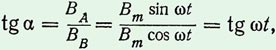
whence α = ω t i.e. the angle between the vector of the resulting field and vertical axis varies linearly in time and, therefore, this vector rotates at a constant speed
But in reality two-phase network is usually absent, and a single-phase motor is started by connecting two coils into one common for them single-phase network. Under such conditions, to obtain a phase shift angle between the currents in the coils, approximately equal to a quarter of the period, one of the coils (working) is connected to the network directly or with a starting active resistance, and the second coil (starting) - through an inductive coil (Fig. 122, a) or a capacitor (Fig. 122, b).
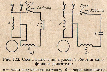
The starting winding is turned on only for the start-up period. At the moment when the rotor reaches a certain speed, the starting winding is disconnected from the network and the motor operates as a single-phase one.
The starting winding is turned off by a centrifugal switch or a special relay.
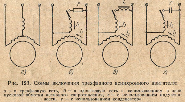
Any three-phase asynchronous motor can be used as a single-phase motor (Fig. 123, a). When a three-phase motor operates as a single-phase, the working or main winding, consisting of two series-connected phases of a three-phase motor, is connected directly to a single-phase network, the third phase, which is a starting or auxiliary winding, is connected to the same network through a starting element - resistance (Fig. 123 , b), inductance (Fig. 123, c) or capacitor (Fig. 123, d).
In single-phase motors low power short-circuited turns placed on the stator poles are used as a starting winding. The stators of such motors are made with salient poles (Fig. 124) and the working winding is laid on the poles in the form of coils, like the excitation winding of a DC machine.
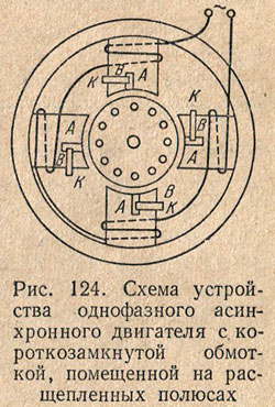
Each pole is divided into two parts, on one of which short-circuited coils are placed. Currents are created in these coils that prevent the passage of magnetic flux in part of the pole IN, as a result of which the magnetic flux in part of the pole A reaches its maximum value earlier than in the part of the pole IN. These two out-of-phase flows excite a rotating magnetic field.
In short-circuited coils, additional losses occur, which reduces the efficiency of the motor. Therefore, this starting method is used only in engines of very low power (up to 100 Tue), where the value of efficiency is not paramount.
The capacitor motor is a single-phase asynchronous motor with two windings on the stator and a squirrel-cage rotor (Fig. 125, a). In contrast to the method of starting single-phase motors through a capacitor, discussed above, in capacitor (two-phase) motors the auxiliary winding is designed for long-term current flow and remains on not only when starting the motor, but also during operation. The presence of a rotating field during engine operation improves the operating properties of this engine in comparison with single-phase ones.
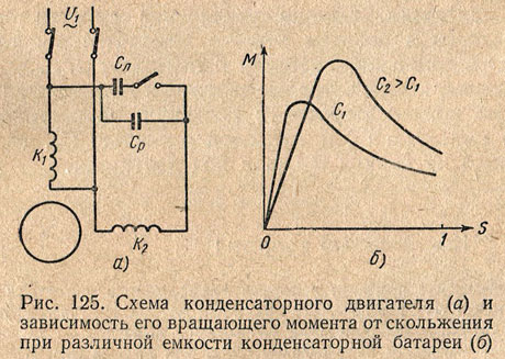
A circular rotating magnetic field in a capacitor motor will be obtained if the magnetizing forces of the two coils are equal, and the magnetizing force of the coil TO 2 must advance the magnetizing force of the coil TO 1 by π/2 in time. This will happen at some specific engine load.
When the load changes, the condition for obtaining a circular rotating field will be violated. In this case, in addition to the circular direct field, a reverse rotating field appears, creating a braking torque that reduces the torque of the machine.
As the capacitor capacity increases, the current also increases, i.e. the motor load will increase, at which a circular rotating field will be created. Therefore, increasing the capacitance of the capacitor bank will cause an increase in the maximum torque of the machine, and the maximum torque shifts to the area of large loads, i.e., large slips (Fig. 125, b).
As the capacity increases, the starting torque of the engine also increases. However, increasing the capacity of the capacitor bank in operating mode is undesirable, since this leads to a decrease in speed and reduces the efficiency of the engine. Therefore, capacitor motors are made with two banks of capacitors - with a constantly switched on or working capacitance WITH p and starting capacity WITH p, switched on only for the period of starting the engine.
 (1 ratings, on average: 5,00 out of 5)