On what values does the capacitance of a flat-plate capacitor depend? Electrostatic capacitance coefficient. Capacitors. Capacity of capacitors of various geometric configurations
Let's consider solitary guide, i.e. a conductor that is distant from other conductors, bodies and charges. Its potential is directly proportional to the charge of the conductor. From experience it follows that different conductors, being equally charged, take on different potentials. Therefore, for a solitary conductor we can write
Value (8.11.1.)
called electrical capacity(or simply capacity) solitary conductor.
The capacity of an isolated conductor is determined by the charge, the communication of which to the conductor changes its potential by one.
The capacitance of a conductor depends on its size and shape, but does not depend on the material, state of aggregation, shape and size of cavities inside the conductor. This is due to the fact that excess charges are distributed across outer surface conductor. Capacitance also does not depend on the charge of the conductor or its potential.
Unit of measurement of electrical capacity - farad(F): 1 F is the capacitance of such an isolated conductor, the potential of which changes by 1 V when a charge of 1 C is imparted to it.
According to the formula, the potential of a solitary ball of radius R located in a homogeneous medium with dielectric constant is equal to
Using formula (8.11.1.), we find that the capacity of the ball
In order for a conductor to have a large capacity, it must have a very big sizes. In practice, however, devices are needed that have the ability, with small sizes and small potentials relative to surrounding bodies, to accumulate significant charges, in other words, to have a large capacity. These devices are called capacitors.
If other bodies are brought closer to a charged conductor, then induced (on the conductor) or associated (on the dielectric) charges appear on them, and the charges closest to the induced charge q will be opposite sign. These charges naturally weaken the field created by charge q, i.e. lower the potential of the conductor, which leads (see (8.11.1.)) to an increase in its electrical capacity.
Capacitor- a device consisting of two conductors (plates) separated by a dielectric.
The capacitance of the capacitor should not be influenced by surrounding bodies, therefore the conductors are shaped in such a way that the field created by the accumulated charges is concentrated in a narrow gap between the plates of the capacitor. This condition is satisfied by: 1) two flat plates; 2) two coaxial cylinders; 3) two concentric spheres. Therefore, depending on the shape of the plates, capacitors are divided into flat, cylindrical And spherical.
Capacitor capacity - This physical quantity, equal to the ratio of the charge q of one of the plates to the potential difference () between its plates:
Let's calculate the capacity flat capacitor, consisting of two parallel metal plates area S each, located at a distance d from each other and having charges +q and -q. If the distance between the plates is small compared to their linear dimensions, then edge effects can be neglected and the field between the plates can be considered uniform. It can be calculated using formulas (8.3.7) and (8.11.4.). If there is a dielectric between the plates, the potential difference between them is:
Where - the dielectric constant.
Then from formula (8.11.4.), replacing q=, taking into account (8.11.5.), we obtain an expression for the capacitance of a flat-plate capacitor:
To determine the capacitance of a cylindrical capacitor consisting of two hollow coaxial cylinders with radii and ( > ), inserted one into the other, again neglecting edge effects, we assume that the field is radially symmetric and concentrated between the cylindrical plates. Let us calculate the potential difference between the plates using the formula for the field of a uniformly charged infinite cylinder with linear density (l is the length of the plates). Taking into account the presence of a dielectric between the plates. Substituting (8.11.9.) into (8.11.4.), we obtain
those. at serial connection of capacitors, the reciprocal values of the capacitances are summed up. Thus, when capacitors are connected in series, the resulting capacitance C is always less than the smallest capacitance used in the battery.
A flat capacitor consists of two parallel plates separated by a small gap of width , filled with a homogeneous dielectric.
We know that the field between two oppositely charged plates with the same surface density is equal to, where S is the area of each plate. Voltage between plates:
Using the definition of capacitor capacitance, we obtain:
Note that the resulting formula is approximate, since it was derived without taking into account the field distortion at the edges of the plates. Calculation using this formula gives an overestimated value of the capacitance and is more accurate the smaller the gap compared to the linear dimensions of the plates.
Capacitance of a spherical capacitor.
A spherical capacitor is a system of two concentric spheres with radii and. According to Gauss's theorem, the electric field between the plates of a spherical capacitor is determined by the charge of the inner sphere. The voltage between the plates is: 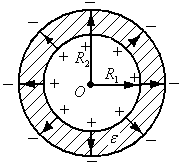
![]() .
.
For the capacitance of a spherical capacitor we obtain:
This formula is accurate.
If , the resulting formula turns into an expression for the capacitance of a parallel-plate capacitor.
Capacitance of a cylindrical capacitor.
A cylindrical capacitor constitutes a system of two coaxial cylinders with radii and length.
Reasoning similarly to the derivation of the capacitance of a spherical capacitor, we obtain:
![]() ..
..
The resulting formula is approximate and, with a small gap, turns into the formula for the capacitance of a flat-plate capacitor.
Connection of capacitors.
In practice, to obtain the required capacitance values, capacitor connections are used: a) series, b) parallel, c) mixed (see figure).

Capacitance of series connection of capacitors.
The charges of the series-connected capacitors are equal, and the voltage across the battery is equal. From the definition of capacity it follows:
If , then (the capacitance of the serial connection is less than the smallest capacitance in the serial connection).
For series-connected capacitors, the capacitance is calculated using the formula:
Capacitance of parallel connection of capacitors.
The battery charge is equal to the sum of the charges:
and voltage. By definition of capacity we get:
For parallel connected capacitors:.
In the case of identical capacitors: .
Estimate the battery capacity (see figure). 
Using the property of infinity, you can imagine the circuit as a connection (see figure).
To calculate the battery capacity we get:
From: , since, then.
Lecture 7.
Dielectrics in electric field.
Dielectrics (insulators) are substances that do not conduct direct electric current. This means that dielectrics do not contain “free” charges that can move over significant distances.
Dielectrics consist of either neutral molecules or ions located at nodes crystal lattice. The molecules themselves can be polar And non-polar. Polar molecules have a dipole moment; non-polar molecules have a dipole moment of zero.
Polarization.
In an electric field, dielectrics are polarized. This phenomenon is associated with the appearance in the volume and on the surface of the dielectric " related» charges. In this case, the final volume of the dielectric acquires a dipole moment. The polarization mechanism is associated with the specific structure of the dielectric. If the dielectric consists of non-polar molecules, then within each molecule there is a displacement of charges - positive along the field, negative against the field, i.e. molecules acquire a dipole moment. In a dielectric with polar molecules in the absence of an external electric field, their dipole moments are randomly oriented.
Under the influence of an electric field, the dipoles are oriented predominantly in the direction of the field. Let's take a closer look at this mechanism (see figure). A pair of forces creates a torque equal to where is the dipole moment of the molecule. This moment tends to orient the dipole along the field. In ionic crystals, under the influence of an electric field, all positive ions are displaced along the field, and negative ions are displaced against the field. Note that the charge displacements are very small even compared to the size of the molecules. This is due to the fact that the strength of the external electric field is usually much less than the strength of the internal electric fields in the molecules. 
Note that there are dielectrics that are polarized even in the absence of an external field (electrets, ferroelectrics). We will focus on considering only homogeneous dielectrics, in which there is no residual polarization, and the volumetric and “bound” charge is always zero.
Capacitor(from lat. condensare- “compact”, “thicken”, or from Lat. condensatio- “accumulation”) - a two-terminal network with a certain or variable capacitance value and low conductivity; a device for accumulating charge and energy of an electric field.
The capacitor is passive electronic component. In its simplest form, the design consists of two plate-shaped electrodes (called linings), separated by a dielectric whose thickness is small compared to the dimensions of the plates (see figure). Practically used capacitors have many layers of dielectric and multilayer electrodes, or strips of alternating dielectric and electrodes, rolled into a cylinder or parallelepiped with four rounded edges (due to winding).
Capacitor in a circuit direct current can conduct current at the moment it is connected to the circuit (the capacitor is charged or recharged); at the end of the transition process, no current flows through the capacitor, since its plates are separated by a dielectric. In the chain alternating current it conducts alternating current oscillations by cyclically recharging the capacitor, closing with the so-called bias current.
In the hydraulic analogy method, the condenser is a flexible membrane inserted into a pipe. The animation shows the membrane being stretched and contracted by the flow of water, analogous to the charging and discharging of a capacitor by an electric current.
From the point of view of the complex amplitude method, the capacitor has a complex impedance
![]() ,
,
Where j - imaginary unit, ω - cyclic frequency ( rad/s) leaking sinusoidal current, f - frequency in Hz, C - capacitor capacity ( farad). It also follows that reactance capacitor is equal to: . For direct current, the frequency is zero, therefore the reactance of the capacitor is infinite (ideally).
The resonant frequency of the capacitor is
![]()
At f > f p A capacitor in an AC circuit behaves like an inductor. Therefore, it is advisable to use a capacitor only at frequencies f< f p , where its resistance is capacitive in nature. Usually maximum operating frequency The capacitor is approximately 2-3 times lower than the resonant one.
The capacitor can accumulate electrical energy. Energy of a charged capacitor:
![]()
Where U - voltage (potential difference) to which the capacitor is charged, and q - electric charge.
Designation of capacitors in diagrams. In Russia conditional graphic symbols capacitors on the circuits must comply with GOST 2.728-74] or international standard IEEE 315-1975:
On electric circuit diagrams The nominal capacitance of capacitors is usually indicated in microfarads (1 μF = 1 10 6 pF = 1 10 −6 F) and picofarads, but often in nanofarads (1 nF = 1 10 −9 F). With a capacity of no more than 0.01 μF, the capacitance of the capacitor is indicated in picofarads, while it is permissible not to indicate the unit of measurement, that is, the postfix “pF” is omitted. When indicating the nominal capacity of a capacity in other units, indicate the unit of measurement. For electrolytic capacitors as well as for high voltage capacitors on the diagrams, after indicating the capacity rating, their maximum operating voltage is indicated in volts (V) or kilovolts (kV). For example: “10 µF x 10 V”. For variable capacitors indicate the range of change in capacity, for example: “10 - 180”. Currently, capacitors are manufactured with nominal capacities from decimal logarithmic series of values E3, E6, E12, E24, that is, there are 3, 6, 12, 24 values per decade, so that the values with the appropriate tolerance (spread) cover the entire decade.
Characteristics of capacitors
Main parameters Capacity The main characteristic of a capacitor is its capacity, characterizing the capacitor’s ability to accumulate electrical charge. The capacitor designation includes the value nominal capacity, while actual capacity may vary significantly depending on many factors. The actual capacitance of a capacitor determines its electrical properties. Thus, according to the definition of capacitance, the charge on the plate is proportional to the voltage between the plates ( q = CU). Typical capacitance values range from units of picofarads to thousands of microfarads. However, there are capacitors (ionistors) with a capacity of up to tens of farads.
The capacitance of a parallel plate capacitor consisting of two parallel metal plates with an area S each located at a distance d from each other, in the SI system it is expressed by the formula: , where is the dielectric constant of the medium filling the space between the plates (in a vacuum it is equal to unity), and is the electrical constant, numerically equal to 8.854187817·10 −12 F/m. This formula is valid only when d much smaller than the linear dimensions of the plates.
To obtain large capacities, capacitors are connected in parallel. In this case, the voltage between the plates of all capacitors is the same. Total battery capacity parallel of connected capacitors is equal to the sum of the capacitances of all capacitors included in the battery.

If all parallel-connected capacitors have the same distance between the plates and the same dielectric properties, then these capacitors can be represented as one large capacitor, divided into fragments of a smaller area.
When capacitors are connected in series, the charges of all capacitors are the same, since they are supplied from the power source only to the external electrodes, and on the internal electrodes they are obtained only due to the separation of charges that previously neutralized each other. Total battery capacity sequentially connected capacitors is equal to
![]()
Or ![]()
This capacity is always less than the minimum capacity of the capacitor included in the battery. However, with a series connection, the possibility of breakdown of capacitors is reduced, since each capacitor accounts for only part of the potential difference of the voltage source.
If the area of the plates of all capacitors connected in series is the same, then these capacitors can be represented as one large capacitor, between the plates of which there is a stack of dielectric plates of all the capacitors that make it up.
Specific capacity Capacitors are also characterized specific capacity- the ratio of capacitance to volume (or mass) of the dielectric. Maximum value specific capacity achieved at minimum thickness dielectric, but this reduces its breakdown voltage.
Energy Density Energy Density electrolytic capacitor depends on design. The maximum density is achieved with large capacitors, where the mass of the housing is small compared to the mass of the plates and electrolyte. For example, an EPCOS B4345 capacitor with a capacity of 12,000 μF, a maximum permissible voltage of 450 V and a mass of 1.9 kg has an energy density at maximum voltage of 639 J/kg or 845 J/l. This parameter is especially important when using a capacitor as an energy storage device, followed by its instant release, for example, in a Gauss gun.
 (1 ratings, on average: 5,00 out of 5)

