How to calculate the value of capacitive currents. Compensation for capacitive ground fault currents
Explanatory note.
Compensation capacitive currents ground faults in 6-35 kV networks.
Introduction. The most common type of damage (up to 95%) in networks of 6, 10, 35 kV are single-phase ground faults (SFG), accompanied by the flow of capacitive current through the fault and high-multiplicity overvoltages on network elements (motors, transformers) in the form of high-frequency transition process. Such impacts on the network lead, at best, to tripping of earth protections. Finding a damaged connection seems to be a labor-intensive and time-consuming organizational task - the sequential disconnection of connections is delayed for a long time and is accompanied by a set of operational switchings for reserving consumers. And, as a rule, most phase-to-phase faults begin with an OZZ. Development single-phase faults to the ground is accompanied by heating of the fault point, dissipation large quantity energy in the place of the OZZ and ends with the disconnection of the consumer by the protection of the MTZ during the transition of the OZZ to short circuit. The situation can be changed by using resonant grounding of the neutral.
Fault currents. In the case of a short-circuit fault, flows to the ground through the damage site. capacitive current, due to the presence electrical capacitance between network phases and ground. The capacitance is concentrated mainly in cable lines, the length of which determines the total capacitive current of the OZZ (approximately 1 km of cable per 1 A of capacitive current).
Types of OZZ. All OZZ are divided into blind (metal) and arc. The most common (95% of all OZZ) and the most dangerous looking OZZ are arc OZZ. Let us describe each type of OZZ separately.
1) from the point of view of overvoltage levels on network elements, metal ground faults are the safest (for example, an overhead power line wire falling to the ground). In this case, a capacitive current flows through the breakdown site, which is not accompanied by large overvoltages due to the specific nature of this type of short circuit.
2) a feature of arc SZZs is the presence of an electric arc at the SZZ site, which is the source of high-frequency oscillations that accompany each SZZ.
Methods for suppressing short circuit currents. There are two ways to suppress SF currents.
1) disconnecting a damaged connection - this method is focused on manual or automatic (using relay protection and automation equipment) disconnection. In this case, the consumer, in accordance with the category, is transferred to backup power or remains without power. There is no voltage on the damaged phase - there is no current through the breakdown site.
2) compensation of capacitive current at the point of closure by a reactor installed in the network neutral, which has inductive properties.
The essence of compensation of capacitive currents of OZZ. As was noted, when a phase is shorted to ground (breakdown), a capacitive current flows through the SFZ. This current, upon closer inspection, is due to the capacitances of the two remaining (intact) phases charged to line voltage. The currents of these phases, shifted relative to each other by 60 electrical degrees, are summed up at the point of damage and have a triple value of the phase capacitive current. From here the magnitude of the residual current through the fault site is determined: . This capacitive current can be compensated by the inductive current of an arc suppression reactor (ARR) installed in the network neutral. During an OZZ in the network at the neutral of any transformer connected to it, the windings of which are connected in a star, a phase voltage appears, which, if there is a neutral terminal connected to the high-voltage winding of the reactor L, initiates the inductive current of the reactor through the breakdown site. This current is directed counter to the capacitive current of the OZZ and can compensate for it with appropriate adjustment of the reactor (Fig. 1)

Rice. 1 Paths for the passage of short-circuit currents through network elements
The need for automatic tuning to resonance. To achieve maximum efficiency of the DGR, the circuit formed by the capacitance of the entire network and the inductance of the reactor - the network zero-sequence circuit (NPC) - must be tuned to resonance at a network frequency of 50 Hz. Under conditions of constant switching in the network (switching on/off of consumers), the network capacity changes, which leads to the need to use continuously adjustable DGRs and automatic system compensation of capacitive currents OZZ (ASKET). By the way, currently used stepped reactors such as ZROM and others are manually adjusted based on calculated data on the capacitive currents of the network, and therefore do not provide resonant tuning.
Operating principle of ASKET. The KNPS is tuned to resonance by an automatic compensation adjustment device of the UARK.101M type, operating on the phase principle. The reference signal (linear voltage) and the 3Uo signal from the measuring transformer (for example, NTMI) are supplied to the UARK.101M input. For correct and stable operation ASKET needs to create an artificial asymmetry in the network, which is done by a neutral excitation source (NVS) - either by connecting a high-voltage capacitor bank to one of the phases of the network, or by installing a special asymmetrical transformer of the TMPS type with a built-in IVS (with the ability to regulate the transformation ratio with a discreteness of 1.25% phase voltage). In the latter case, the voltage value 3Uo in resonance mode and the stability of ASKET operation remain constant when the network configuration changes (see formulas below). A DGR (for example, RDMR type) is installed in the neutral of the same transformer. Thus, ASKET is presented as a system TMPS+RDMR+UARK.101M.
On the relationship between the values of natural and artificial asymmetry. Online with isolated neutral the voltage across the open triangle STMI, taking into account the transformation ratio, corresponds to stress of natural asymmetry. The magnitude and angle of this voltage are unstable and depend on various factors(weather,…..etc.), so for proper operation ASKET needs to create a more stable signal both in magnitude and phase. For this purpose, a neutral excitation source ( source of artificial asymmetry). If we use the terminology of the theory automatic control, artificial asymmetry is a useful signal used to control the CNPS, and natural asymmetry is an interference from which it is necessary to tune out by choosing the value of artificial asymmetry. In networks with availability cable lines with a capacitive current of 10 amperes or more, the amount of natural asymmetry is usually very small. P.5.11.11. PTEESiS limits the magnitude of the unbalance voltage (natural + artificial) in networks operating with capacitive current compensation at the level of 0.75% of the phase voltage, and the maximum degree of neutral displacement at a level not exceeding 15% of the phase voltage. On an open STMI triangle, these levels will correspond to the values 3Uo = 0.75V and 15V. The maximum degree of neutral displacement is possible in resonance mode (Fig. 2).
Below are the formulas for calculating the voltage 3Uo in resonance mode for two methods of creating artificial asymmetry:
1) in case of using a Co capacitor
 ,
,
where is the angular frequency of the network, 314.16 s-1,
http://pandia.ru/text/79/550/images/image006_44.gif" width="24" height="23 src="> - phase EMF, V,
http://pandia.ru/text/79/550/images/image008_37.gif" width="29" height="27">- transformation ratio for 3Uo of an instrument transformer, in a 6 kV network - 60/, in a 10 network kV - 100/http://pandia.ru/text/79/550/images/image010_32.gif" width="97" height="51">,
where Kcm is the switchable phase shift coefficient B of a special transformer.
From the formulas it is clear that in the case of using a capacitor Co, the value of 3Uo at the resonance point depends on the capacitive current of the network (), and in the case of using a special asymmetrical transformer it does not depend.
The minimum value 3Uo is selected based on the condition reliable operation device UARK.101M, and is 5V.
The above formulas do not take into account the voltage value of the natural asymmetry of the network due to its small values..jpg" width="312" height="431">
Rice. 3 Voltage vectors in a resonant-grounded network
Conclusions:
Precise automatic compensation of capacitive current OZZ is a non-contact means of arc extinguishing and, in comparison with networks operating with an isolated neutral, resistively grounded, partially compensated, and also with a combination grounded neutral has the following advantages:
reduces the current through the fault site to minimum values (limited to active components and higher harmonics), ensures reliable arc extinguishing (prevents prolonged exposure to a grounding arc) and safety when currents spread in the ground;
simplifies the requirements for grounding devices;
limits overvoltages arising from arc faults to values of 2.5-2.6 Uph (with a degree of compensation detuning of 0-5%), safe for the insulation of operating equipment and lines;
significantly reduces the rate of voltage recovery in the damaged phase, helps restore the dielectric properties of the fault location in the network after each extinguishing of the intermittent grounding arc;
prevents surges of reactive power on power supplies during arc faults, thereby maintaining the quality of electricity for consumers;
prevents the development of ferroresonant processes in the network (in particular, spontaneous displacements of the neutral), if restrictions on the use of fuses on power lines are met;
eliminates restrictions on static stability when transmitting power via power lines.
When compensating for capacitive currents, overhead and cable networks can operate for a long time with a phase shorted to ground.
Literature:
1. Likhachev to ground in networks with an isolated neutral and with compensation of capacitive currents. M.: Energy, 1971. – 152 p.
2. Obabkov adaptive control systems for resonant objects. Kyiv: Naukova Dumka, 1993. – 254 p.
3. Fishman V. Methods of neutral grounding in 6-35 kV networks. Designer's point of view. Electrical Engineering News, No. 2, 2008
4. Rules technical operation power stations and networks Russian Federation. RD 34.20.501 edition. Moscow, 1996.
Chief Engineer

Rice. 2 Examples of resonant characteristics of CNPS

Rice. 4 Reaction of a resonant-grounded network to an arc breakdown
Page 1 of 5
Phase-to-ground fault in networks operating with an isolated neutral and with capacitive current compensation
In three-phase electrical network operating with an insulated neutral, a phase-to-ground fault is detected by the readings of insulation monitoring voltmeters. Voltmeters are connected to the main terminals secondary winding three-phase three-winding voltage transformer of the NTMI series, each phase of which has a separate armored magnetic circuit, designed for a long-term increase in induction. In case of a metal phase-to-ground fault (Fig. 10.1, A) the voltage transformer winding of the damaged phase of the network becomes short-circuited and its voltmeter reading drops to zero. The other two phases will be under line voltage. The induction in the magnetic circuits of these phases will increase by √3 times, and voltmeters will show linear voltages.
At the point of phase fault to ground, a current passes equal to the geometric sum of the capacitive currents of the undamaged phases:
Where I
c - ground fault current, A;
WITH- network capacity, F;
w=2pf - angular frequency, s-1.
The longer the network, the greater its capacity and, therefore, the more more current ground fault.
A phase to ground fault does not change the symmetry of line voltages and does not disrupt the power supply to consumers. However, the danger of a phase-to-ground fault is that an intermittent ground arc usually occurs at the fault location, long burning which, with a large capacitive current, leads to a thermal effect and significant ionization of the surrounding space, which creates favorable conditions for the occurrence of phase-to-phase short circuits. The intermittent nature of the grounding arc leads to dangerous overvoltages (up to 3.2 U F), spreading throughout the network. If in this case the insulation in certain sections of the network turns out to be reduced (for example, due to contamination and moisture), then arc overvoltages can lead to phase-to-phase flashovers and emergency equipment shutdowns. But even in the absence of arc overvoltages, an increase in itself to the linear voltage of two phases can already lead to a breakdown of defective insulation.
Purpose of arc suppression reactors. The operational task is to reduce the ground fault current and thereby ensure rapid extinction of the grounding arc. To do this, it is necessary that the capacitive ground fault currents do not exceed the following values:
Mains voltage, kV................................... |
||||
Capacitive current, A………………… |
These currents comply with the requirements of the PTE. However, experience shows that to ensure reliable self-extinguishing of the arc in 6 and 10 kV networks, it is advisable to reduce capacitive currents to 20 and 15 A, respectively. If the specified current values are exceeded, an arc suppression reactor is switched on in the neutral winding of the transformer (Fig. 10.1, b), reducing (compensating) capacitive current through the fault location to minimum values.
Inductive current of arc suppression reactor I R arises as a result of the influence of neutral bias voltage on it U 0
=-
U.A. appearing on the neutral when a phase is shorted to ground. The current is: ![]()
Where LP And LT -
inductance of the arc suppression reactor and transformer, respectively, H;
U F- phase voltage.
With capacitive current compensation, overhead and cable networks can operate for some time with a phase-to-ground fault.

Rice. 10.1. Phase-to-ground fault in a network with an isolated neutral (A) and with capacitive current compensation (b) :
1 -
transformer feeding the network; 2
- measuring voltage transformer;
3 -
arc suppression reactor; TO V -
voltage relay
Selecting the settings for arc suppression reactors. At IP =IC=0, the capacitive component of the current at the point of the ground fault is completely compensated by the inductive current of the reactor - current resonance occurs. Arc suppression reactors usually have a resonant setting, which makes it easier to extinguish the arc. Deviation from the resonant tuning is called compensation detuning. In practice, settings with overcompensation are allowed ( IP >IC), if the reactive component of the ground fault current is no more than 5 A, and the degree of detuning does not exceed 5%. Undercompensation setting ( IP <IC) can be used in cable and overhead networks if any emergency asymmetries of phase capacitances do not lead to the appearance of a neutral bias voltage exceeding 0.7 U F .
The ground fault current is determined by compensation detuning, active insulation leaks and uncompensated higher harmonic currents. With resonant tuning, the circuit current is minimal, and, as experience shows, overvoltages in the network do not exceed 2,7
U F .
When operating overhead networks, they often deviate from resonant tuning in order to eliminate distortions of phase voltages on substation buses, which are mistakenly mistaken by personnel for incomplete ground faults. The fact is that in any 6-35 kV overhead network there is always an asymmetry of the phase capacitances relative to the ground, which depends on the location of the wires on the supports and the phase distribution of the coupling capacitors. This causes some unbalance voltage to appear on the neutral U NS. Degree of asymmetry ( u0= U NS /
U F )
×
100 usually does not exceed 1.5%. For 10 kV networks, for example, it is about 100V and practically in normal operation of the network does not affect the readings of voltmeters measuring phase voltages.
The inclusion of an arc suppression reactor in the neutral significantly changes the potentials of the neutral and network wires. Neutral bias voltage appears at neutral U 0
,
caused by the presence of asymmetry in the network. This voltage will be applied to the terminals of the arc suppression reactor. With resonant tuning, the neutral bias voltage can reach values comparable to the phase voltage. It will lead to distortion of phase voltages and even the appearance of a “ground in the network” signal, although there is no ground fault at this time. By detuning the arc suppression reactor, it is possible to move away from the resonance point (the oscillatory circuit is formed by the inductance of the reactor and the total capacitance of the network phases), reduce the neutral bias voltage and equalize the voltmeter readings. In the absence of a ground fault in the network, the neutral offset is allowed no more than 0.15 U F. However, from the point of view of arc extinction, the optimal setting is still the resonant setting. Any compensation detuning leads to an increase in the current passing at the fault location in the network operating mode with a ground fault, and is therefore not recommended. When there is a large neutral displacement, measures should be taken to reduce the asymmetry of the capacitors in the network. In cable networks, exclusively resonant tuning is used, since the cable phase capacitances are symmetrical and there is practically no unbalance voltage there.
Maintenance of arc suppression reactors. The current of arc suppression reactors of various types is regulated by manual switching of branches with disconnection of the reactor from the network, a smooth change in the gap in the magnetic system produced by an electric motor drive without disconnecting the reactor from the network, changing the inductance of the reactor by DC bias without disconnecting the reactor from the network.
In the last two cases, the setting is carried out by automatic compensation settings (ANC), which activate the control actuators only in normal operation, when there is no ground fault in the network.
An automated normally compensated network must have:
- arc suppression reactors with manual tap switching, designed to compensate for capacitive currents mainly in the base part of the regulation;
- tuning arc suppression reactors with a smooth change in compensation current without disconnecting the reactor from the network. Current regulation should be carried out by the dispatcher using ANC and telemechanics devices;
- arc suppression reactors with automatic regulators (optimizers) of compensation current (ANKZ system), which come into operation immediately after the occurrence of a ground fault and bring the network to a resonant tuning mode in order to eliminate the arc at the point of damage. 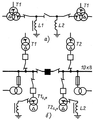
Rice. 10.2. Connection diagram of arc suppression reactors to network supply transformers (A) and to auxiliary transformers (b)
Reconstruction of arc suppression reactors by substation personnel is carried out by order of the dispatcher, who selects the setting in connection with the upcoming change in the network configuration. In doing so, he is guided by a setting selection table compiled for specific sections of the network based on the results of measurements of ground fault currents, capacitive currents, compensation currents and network neutral bias voltages.
If the reactor is rebuilt manually, then the personnel verify by signaling devices that there is no ground fault in the network and turn it off with a disconnector. After installing and fixing the specified branch, the reactor is connected to the network by a disconnector. Manual switching of branches without disconnecting the reactor from the network is not allowed for safety reasons, since during the restructuring process it is possible that a ground fault may occur and phase voltage may appear on the reactor. 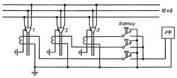
Rice. 10.3. Ground fault alarm circuit using isolation filter (RF)):
1-3 -
outgoing cable lines
Arc suppression reactors are installed at substations supplying the network and connected to transformer neutrals through disconnectors (Fig. 10.2, A). When connecting a transformer according to a star-delta circuit, the reactors are connected to the neutrals of the auxiliary transformers (Fig. 10.2, b), which are most often used as auxiliary transformers. The power of the auxiliary transformer is selected taking into account the load connected to it and the inductive current, which additionally loads the transformer in the mode of circuit-to-ground fault.
To transfer a reactor from one transformer to another, it is first disconnected with a disconnector from the neutral of one transformer, and then connected with a disconnector to the neutral of the other. It is not necessary to combine the neutrals of transformers through the zero bus, since when transformers operate separately into unconnected sections of the network, in the event of a ground fault in one of them, the voltage at the neutral U 0
will equally change the phase voltages on the substation buses of both sections, and it will become impossible to establish the section where the ground fault occurred without disconnecting the transformer from the network.
Signaling devices and ground fault detection. It was stated above that networks with capacitive current compensation can be operated in the presence of a ground fault. But since a prolonged increase in voltage on two phases and the passage of small conduction currents to the ground increase the likelihood of an accident, and in the event of a wire break and falling to the ground, a danger is created for the lives of people and animals, the damage must be found and repaired as quickly as possible. Personnel learn about a ground fault that has occurred in the network by the operation of signaling devices, and the phase connected to the ground is determined by the readings of insulation monitoring voltmeters.
In the signaling device, the insulation monitoring relays are connected to the terminals of the additional secondary winding of the NTMI voltage transformer, connected according to an open delta circuit. If the insulation of a phase to ground is broken, a zero-sequence voltage 3 appears at the terminals of this winding U 0
, relay KV triggers and gives a signal (see Fig. 10.1).
In networks with capacitive current compensation, signaling and control circuits for the operation of arc suppression reactors are connected either to the reactor current transformer or to its signal winding.
Lamps for monitoring the absence of a short circuit in the network, installed directly at the disconnector drive, are also connected to the signal winding of the reactor. The lamps are switched on without fuses, and therefore the insulation of their circuits must be sufficiently reliable. Alarm circuits typically have electromagnetic interlock circuits that prevent tripping of the reactor disconnectors during a ground fault.
Based on the signals received at substations, it is impossible to immediately determine the electrical circuit on which the ground fault occurred, since all outgoing lines have an electrical connection with each other on busbars. To determine an electrical circuit that has a ground fault, selective signaling of damaged sections is used, based on the use of transient fault currents or higher harmonic currents, the source of which is nonlinear circuits.
Currently, the most widely used devices at substations supplying cable networks are devices with separating filters of the RF and USZ types (in a stationary version - USZ 2/2; in a portable version, used in conjunction with current clamps - USZ-3). These devices respond to higher harmonics contained in current 3 I 0
. Their level is proportional to the capacitive current of the network and in a damaged line is always significantly higher than in the zero-sequence currents of undamaged lines. This is precisely what serves as a sign of damage on one line or another.
The RF type device operates in the frequency range of 50 and 150Hz. In compensated networks, as a rule, the 150Hz range is used. To monitor the level of higher harmonics at substations, tables of instrument readings at a frequency of 150 Hz, taken in normal load mode in the absence of a single-phase ground fault, are compiled for each line. These indications must be systematically checked. The readings of the device are compared with them when finding a damaged connection. In case of large undercompensation or in the absence of compensation in the network, the device switches to the 50 Hz range.
Stationary devices are installed on control panels or in the corridors of switchgears and, using buttons, switches or step finders, when a ground fault appears in the network, they are alternately connected by personnel to zero-sequence current transformers (ZCTs) installed on each cable line (Fig. 10.3).
A connection is considered damaged if, during measurement, the instrument needle deviates by a greater number of divisions than when measuring at all other connections.
Mosenergo has developed and put into operation a device of the KSZT-1 type (a modernized version of KDZS) for automatically searching for a cable line with a stable phase-to-ground fault. By means of alternate measurements on the TTNP, it determines a cable line with damaged insulation by the maximum level of higher harmonic current in it. Information via the TC channel in the form of a conditional code is transmitted to the control center, where the decoder is converted into a number that makes up the name of the line.
In the absence of TTNP on cable lines, to find a damaged connection, use a current clamp as a measuring current transformer. When taking measurements, the HSS device is installed on a clamp instead of a current-collecting ammeter.
If selective signaling devices at the substation are missing or do not give the desired results, the search for the damaged connection is carried out by transferring individual connections from one bus system (section) to another operating without a ground fault, or by dividing the electrical network in predetermined places. These operations must be carried out in such a way that when dividing the network, its individual parts are fully compensated. To find faults, they sometimes use alternating short-term disconnections of lines and putting them into operation by automatic reclosure or manually.
Simultaneously with finding the location of the fault in the network, inspections of operating reactors and transformers to the neutrals of which they are connected must be carried out. This is due to the fact that the duration of continuous operation of reactors under current is normalized by factories for individual branches from 2 to 8 hours. If the search for a ground fault is delayed, personnel must carefully monitor the temperature of the upper layers of oil in the reactor tank, recording thermometer readings every 30 minutes . The maximum temperature increase in the upper layers of oil is allowed up to 100°C. If the reactors are installed at substations serviced by operational field teams (OVB), then after finding and disconnecting the damaged line, the reactors are inspected, the readings of their thermometers are recorded and all specified relays and signaling devices are returned to their original positions.
In electrical engineering there is such a thing as capacitive current, better known as capacitive ground fault current in electrical networks. This phenomenon occurs when a phase is damaged, resulting in a so-called grounding arc. In order to avoid serious negative consequences, it is necessary to timely and correctly calculate the capacitive current of the network. This will reduce the overvoltage in case of re-ignition of the arc and create conditions for its independent extinction.
What is capacitive current
Capacitive current usually occurs on long lines. In this case, the ground and conductors work similarly to the plates of a capacitor, contributing to the appearance of a certain capacitance. Since it has variable characteristics, this can serve as an impetus for its appearance. In cable lines with a voltage of 6-10 kilovolts, its value can be 8-10 amperes per 1 km of length.
If a line is disconnected in an unloaded state, the value of the capacitive current can reach several tens or even hundreds of amperes. During the shutdown process, when the moment the current passes through zero, there will be no voltage on the diverging contacts. However, at the next moment the formation of an electric arc is quite possible.
If the capacitive current value does not exceed 30 amperes, it will not cause any serious damage to the equipment in the area of dangerous overvoltages and ground faults. The electric arc that appears at the site of the fault goes out quickly enough with the simultaneous appearance of a stable short circuit to the ground. All changes in capacitive current occur along the electric line, in the direction from end to beginning. The magnitude of these changes will be proportional to the length of the line.
In order to reduce the ground fault current, in networks with voltages from 6 to 35 kilovolts, capacitive current is compensated. This allows you to reduce the speed of voltage recovery on the damaged phase after the arc is extinguished. In addition, overvoltages in the event of repeated arc ignitions are reduced. Compensation is carried out using arc-quenching grounding reactors with smooth or stepwise inductance adjustment.

The arc suppression reactors are adjusted in accordance with the compensation current, the value of which is equal to the capacitive ground fault current. When setting up, it is allowed to use excessive compensation parameters when the inductive component of the current is no more than 5 amperes, and the degree of deviation from the main setting is 5%.
Setting up with insufficient compensation is only permissible if the power of the arc suppression reactor is insufficient. The degree of detuning in this case should not exceed 5%. The main condition for such a setting is the absence of neutral bias voltage, which can occur when the phase capacitances of the electrical network are asymmetrical - when wires are broken, cable cores are stretched, etc.
In order to prevent emergency situations in advance and take appropriate measures, it is necessary to calculate the capacitive current in a certain area. There are special techniques that allow you to obtain accurate results.
An example of calculating the capacitive current of a network
The value of the capacitive current arising during a phase-to-ground fault is determined only by the value of the network capacitance. Compared to inductive and active reactances, capacitive reactance has higher performance. Therefore, the first two types of resistance are not taken into account in the calculations.

It is most convenient to consider the formation of capacitive current using the example of a three-phase network, where a normal short circuit has occurred in phase A. In this case, the magnitude of the currents in the remaining phases B and C is calculated using the following formulas:
The current modules in these phases I in and I c, taking into account certain assumptions C = C A = C B = C C and U = U A = U B = U C, can be calculated using another formula: The value of the current in the ground consists of a geometric the sum of the currents of phases B and C. The entire formula will look like this: When carrying out practical calculations, the magnitude of the ground fault current can be determined approximately by the formula: , where U avg.nom. - is the phase average rated voltage of the stage, N is the coefficient, and l is the total length having an electrical connection with the ground fault point (km). The estimate obtained using this calculation indicates that the current value is independent of the location of the fault. This value is determined by the total length of all network lines.
How to compensate for capacitive ground fault currents
The operation of electrical networks with voltages from 6 to 10 kilovolts is carried out with an insulated or grounded neutral, depending on the strength of the ground fault current. In all cases, arc suppression coils are included in the circuit. The neutral is grounded using arc suppression coils to compensate for ground fault currents. When a single-phase ground fault occurs, the operation of all electrical receivers continues in normal mode, and the power supply to consumers is not interrupted.

The considerable length of urban cable networks leads to the formation of large capacitance in them, since each cable is a kind of capacitor. As a result, a single-phase fault in such networks can lead to an increase in the current at the fault site to several tens, and in some cases, hundreds of amperes. Exposure to these currents leads to rapid destruction of the cable insulation. Because of this, in the future, a single-phase fault becomes two- or three-phase, causing a section shutdown and interrupting the power supply to consumers. At the very beginning, an unstable arc occurs, which gradually turns into a permanent ground fault.
When the current passes through zero, the arc first disappears and then appears again. At the same time, an increase in voltage occurs on undamaged phases, which can lead to insulation failure in other areas. To extinguish the arc in a damaged area, it is necessary to take special measures to compensate for the capacitive current. For this purpose, an inductive grounding arc suppression coil is connected to the network zero point.
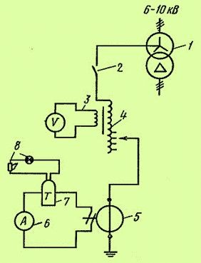
The arc extinguishing coil connection circuit shown in the figure consists of a grounding transformer (1), a switch (2), a voltage signal winding with a voltmeter (3), an arc extinguishing coil (4), a current transformer (5), (6), a current relay ( 7), sound and light alarm (8).
The coil structure consists of a winding with an iron core placed in a casing filled with oil. The main winding has taps corresponding to five current values to enable adjustment of the inductive current. One of the terminals is connected to the zero point of the transformer winding connected by a star. In some cases, a special grounding transformer may be used, and the main winding terminal is connected to ground.
Thus, to ensure safety, not only the capacitive current is calculated, but also carried out using special devices. In general, this gives good results and ensures safe operation of electrical networks.
Calculation of capacitive phase-to-ground fault current. When a phase is shorted to ground, called a simple fault, the current is determined only by the capacitance of the network. The capacitive resistances of network elements significantly exceed their inductive and active resistances, which makes it possible to neglect the latter when determining the current. Let's consider the simplest three-phase network in which a simple phase short circuit has occurred A.
Currents in phases IN And WITH are defined as follows:
Current modules taking into account assumptions
are calculated as The current in the ground is determined by the geometric sum of the currents: ![]() In practical calculations, a rough estimate of the magnitude of the ground fault current is possible using the formula
In practical calculations, a rough estimate of the magnitude of the ground fault current is possible using the formula  where av.nom U– average rated phase voltage of the stage; N- coefficient; l– total length of overhead or cable lines electrically connected to the ground fault point, km. This assessment means that the magnitude of the fault current does not depend on its location and is determined by the total length of the network lines.
Compensation of capacitive phase-to-ground current.
In networks of 3–20 kV and a short length of overhead lines and cable lines, the phase-to-ground fault current is several amperes. The arc in this case turns out to be unstable and goes out on its own. Consequently, such networks can operate normally in a simple circuit mode. An increase in the voltage and length of the network leads to an increase in the ground fault current - an arc at such currents can burn for a long time, it often transfers to adjacent phases, turning a single-phase fault into a two- or three-phase one. Rapid elimination of the arc is achieved by compensating for the ground fault current by grounding the neutral through the arc extinguishing device
The network consists of a transformer and a line connected to constant voltage buses. The symmetrical components at the point of the ground fault are determined under the assumption that the total capacitive resistance of the zero-sequence circuit significantly exceeds its positive and negative sequence resistance, which allows us to accept. 
![]()
61.1.
In a comprehensive scheme ( b) the inductive reactances of the line and tr-ra of all sequences are symbolically introduced, although they are assumed to be equal to zero. To limit the current of a simple ground fault, it is necessary to ground the neutral of the transformer through an inductance, the value of which is selected so that a current resonance occurs in the zero-sequence circuit. In this case, which leads to the complete disappearance of the ground fault current. Neglecting the inductive reactances of the transformer and line, we find that resonance occurs at. Arc suppression reactors have stepwise inductance regulation. With their help, the single-phase fault current is reduced tens of times, which is quite enough to extinguish the arc at the fault point. 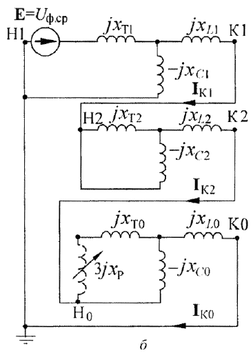
In normal network operation there is always a slight neutral offset, i.e. The neutral potential is always different from zero. This occurs due to phase asymmetry of power lines, which cannot be eliminated in distribution networks. But when the arc suppression reactor is turned on in neutral, its potential can increase significantly.
According to the PUE, the degree of phase asymmetry of capacitors relative to the ground should not exceed 0.75%. A slight detuning of the resonant circuit, which does not lead to a deterioration in arc extinction conditions, is especially effective in networks that do not have transposition. PUEs do not limit the duration of network operation with a phase-to-ground fault.
 (1 ratings, on average: 5,00 out of 5)

