Electrical capacity of parallel capacitors. Electrical capacity. Capacitors. Connection of capacitors
Electrical capacity– a quantitative measure of a conductor’s ability to hold a charge.
The simplest methods of separating opposite electric charges - electrification and electrostatic induction - allow you to obtain on the surface of bodies a large number of free electric charges. To accumulate significant quantities of opposite electrical charges, they are used capacitors.
Capacitor is a system of two conductors (plates) separated by a dielectric layer, the thickness of which is small compared to the size of the conductors. So, for example, two flat metal plates, located parallel and separated by a dielectric layer, form flat capacitor.
If the plates flat capacitor report charges equal in magnitude opposite sign, then the electric field strength between the plates will be twice as strong as the field strength at one plate. Outside the plates, the electric field strength is zero, since equal charges different sign on two plates, electric fields are created outside the plates, the strengths of which are equal in magnitude but opposite in direction.
Capacitance of the capacitor is a physical quantity determined by the ratio of the charge of one of the plates to the voltage between the plates of the capacitor:
When the position of the plates remains unchanged, the electrical capacity of the capacitor is constant value for any charge on the plates.
The unit of electrical capacity in the SI system is Farad. 1 F is the electrical capacity of such a capacitor, the voltage between the plates of which is equal to 1 V when the plates are given opposite charges of 1 C each.
The electrical capacity of a flat capacitor can be calculated using the formula:
S – area of capacitor plates
d – distance between plates
– the dielectric constant dielectric
The electrical capacity of the ball can be calculated using the formula:
Energy of a charged capacitor.
If the field strength inside the capacitor is E, then the field strength created by the charge of one of the plates is E/2. In the uniform field of one plate there is a charge distributed over the surface of the other plate. According to the formula for the potential energy of a charge in a uniform field, the energy of the capacitor is equal to:
Using the formula for capacitance of a capacitor:
![]()
End of work -
This topic belongs to the section:
Interaction of currents, strength of interaction, magnetic field, how it reacts
Electric charge... Interaction of charges Coulomb's Law... Electric field definition, tension potential, drawing of the electric field...
If you need additional material on this topic, or you did not find what you were looking for, we recommend using the search in our database of works:
What will we do with the received material:
If this material was useful to you, you can save it to your page on social networks:
| Tweet |
All topics in this section:
Let us list the properties of charges
1. There are two types of charges; negative and positive. Like charges attract, like charges repel. The bearer of the elementary, i.e. the smallest, negative charge is
Interaction of charged bodies
Electrostatics studies the properties and interactions of electrically charged bodies or particles stationary in an inertial reference frame. The simplest phenomenon in which the fact of existence is revealed
Coulomb's law
Charges distributed on bodies whose dimensions are significantly smaller than the distances between them can be called point charges, since in this case neither the shape nor the size of the bodies significantly affect the interaction
Electric field
The interaction of electric charges is explained by the fact that around each charge there is electric field. The electric field of a charge is a material object, it is continuous in space
Electric field strength
Charges, being at a certain distance from one another, interact. This interaction is carried out through an electric field. The presence of an electric field can be detected by placing in
Potential.
Potential difference. Besides the tension important characteristic electric field is potential j. Potential j is the energy characteristic of the electric field, then
Dielectrics in an electric field
Dielectrics or insulators are bodies that cannot conduct electrical charges through themselves. This is explained by the absence of free charges in them. If one end of the dielectric
Polar and non-polar dielectrics
Non-polar dielectrics include those in whose atoms or molecules the center of the negatively charged electron cloud coincides with the center of the positive atomic nucleus. For example, inert gases, acid
Polarization of non-polar dielectrics
In the absence of an electric field, the electron cloud is located symmetrically relative to the atomic nucleus, and in an electric field it changes its shape and the center of the negatively charged electron
The dielectric constant
The dielectric constant of a substance is a physical quantity equal to the ratio of the modulus of the electric field strength in a vacuum to the electric field strength in a homogeneous dielectric
Conductors in an electric field
Conductors are bodies that can pass electrical charges through themselves. This property of conductors is explained by the presence of free charge carriers in them. Examples of conductors could be
Electric field work when moving a charge
For trial electric charge placed in an electrostatic field, a force acts that causes this charge to move. This means that this force does work to move the charge. We get the formula
Potential difference
A physical quantity equal to the work that field forces do when moving a charge from one field point to another is called the voltage between these field points.
Capacitors.
If an insulated conductor is given a charge Dq, then its potential increases by Dj, and the ratio Dq/Dj remains constant: Dq/Dj=C, where C is the electrical capacitance of the conductor,
Electricity
This is the directed movement of charged particles. In metals, current carriers are free electrons, in electrolytes - negative and positive ions, in semiconductors - electrons and holes, in g
Current strength
Current strength is the ratio of the charge carried through the cross-section of a conductor during a time interval to this time interval.
Electromotive force
In order for an electric current to exist in a conductor for a long time, it is necessary to maintain unchanged the conditions under which the electric current occurs. In the external circuit electrically
Conductor resistance
Resistance is basic electrical characteristics conductor. The conductor resistance can be determined from Ohm's law:
Dependence of conductor resistance on temperature.
If you pass current from a battery through a steel spiral, the ammeter will show a decrease in current. This means that with temperature resistance, the resistance of the conductor changes. If
Superconductivity
In 1911, the Dutch scientist Kamerlingh Onnes discovered that when the temperature of mercury was lowered to 4.1 K, it resistivity decreases abruptly to zero. The phenomenon of decreasing resistivity
Series and parallel connection of conductors
Conductors in electrical circuits direct current can be connected in series and in parallel. At serial connection the electrical circuit has no branches
Ohm's law for a complete circuit
If, as a result of the passage of direct current in a closed circuit electrical circuit only heating of the conductors occurs, then according to the law of conservation of energy full time job electric current in a closed circuit
Kirchhoff's rule.
When several current sources are connected in series, the total emf of the battery is equal to the algebraic sum of the emf of all sources, and the total resistance is equal to the sum of the resistances. With parallel p
Current power
This is the work done per unit of time and is equal to P=A/t=IU=I2R=U2/R. Full power P0, developed by the source, is used to release heat in the external and internal
Work and current power
The work done by the forces of the electric field that creates an electric current is called the work of the current. The work of electric field forces or the work of current on a section of a circuit with electrical resistance R per time
A magnetic field.
Around conductors carrying current and permanent magnets there is a magnetic field. It occurs around any directionally moving electric charge, as well as in the presence of a time-varying electric charge.
Magnetic interaction of currents
Between stationary electric charges there are forces determined by Coulomb's law. Each charge creates a field that acts on another charge and vice versa. However, between electric charges
A magnetic field
Just as an electric field arises in the space surrounding stationary electric charges, a magnetic field arises in the space surrounding moving charges. Electrics
The effect of a magnetic field on a moving charge. Lorentz force
Electricity is a collection of orderedly moving charged particles. Therefore the action magnetic field on a conductor with current is the result of the action of the field on moving charged particles in
Ampere's law
Let us place a conductor of length l in a magnetic field through which a current I flows. The conductor is acted upon by a force directly proportional to the strength of the current flowing through the conductor, the magnetic field induction, the length
Ampere's law
The force acting on a current-carrying conductor in a magnetic field is called the Ampere force. Experimental study of magnetic interaction shows that the ampere force modulus is proportional to
Magnetic flux
Magnetic flux through a certain surface is a physical quantity equal to the total number of magnetic induction lines penetrating this surface. Consider a homogeneous magnet
Magnetic,
a term applied to all substances when considering their magnetic properties. The variety of types of microorganisms is due to the difference in the magnetic properties of the microparticles that form the substance, as well as the nature of the interaction
Magnetic properties of matter
All substances placed in a magnetic field are magnetized, that is, they themselves create a magnetic field. Therefore, the magnetic field induction in a homogeneous medium differs from the field induction in a vacuum. Fi
Magnetic flux.
Magnetic flux Ф through a certain surface S is a scalar quantity equal to the product of the magnitude of the magnetic induction vector by the area of this surface and the cosine of the angle between the normal n to
Electromagnetic induction
The occurrence of emf in a closed conducting circuit when the magnetic flux changes through this surface, limited by this circuit, is called electromagnetic induction. Also induced emf, and trace
Magnetic field induction
Magnetic field induction is a characteristic of the ability of a magnetic field to exert a force on a current-carrying conductor. It is a vector physical quantity. Beyond the direction
Electromagnetic induction
If an electric current creates a magnetic field, then couldn't the magnetic field in turn create an electric current in a conductor? Michael Faraday was the first to find the answer to this question. In 1831
Law of Electromagnetic Induction
An experimental study of the dependence of induced emf on changes in magnetic flux led to the establishment of the law of electromagnetic induction: induced emf in a closed loop p
Self-induction phenomenon
Current flowing through a conductive circuit creates a magnetic field around it. The magnetic flux Ф associated with the circuit is directly proportional to the current strength in this circuit: Ф=LI, where L is the inductance of the circuit.
The phenomenon of self-induction. Inductance
Electric current passing through a conductor creates a magnetic field around it. The magnetic flux through the loop of this conductor is proportional to the modulus of induction of the magnetic field inside the loop, and in
Magnetic field energy
When the inductor coil is disconnected from the current source, an incandescent lamp connected parallel to the coil gives a short-term flash. The current in the circuit arises under the influence Self-induced emf. Source
Electromagnetic waves.
According to Maxwell's theory, an alternating magnetic field causes the appearance of an alternating vortex electric. field, which, in turn, causes the appearance of an alternating magnetic field, etc. Thus
Electromagnetic wave scale.
Electromagnetic waves are generated over a wide range of frequencies. Each part of the spectrum has its own name. Thus, visible light corresponds to a rather narrow range of frequencies and, accordingly, wavelengths
Lasers and masers (stimulated emission effects, circuits)
, a source of electromagnetic radiation in the visible, infrared and ultraviolet ranges, based on stimulated emission of atoms and molecules. The word "laser" is made up of the initial
Geometric optics
, a branch of optics that studies the laws of light propagation based on ideas about light rays. A light ray is understood as a line along which a flow of light energy propagates.
Farm principle,
basic principle of geometric optics. Simplest form F.p. - the statement that a ray of light always propagates in space between two points along the path along which it travels
Polarization of light
one of the fundamental properties of optical radiation (light), consisting in the inequality of different directions in a plane perpendicular to the light beam (the direction of propagation of the light wave
Interference of light.
This is the phenomenon of waves superposing to form a stable pattern of highs and lows. When light interferes, alternating light and dark stripes are observed on the screen if the light is monochromatic (and
Diffraction of light.
The phenomenon of waves bending around obstacles and light entering the geometric shadow region is called diffraction. Let a plane wave fall on a slit in a flat screen AB. According to the Huygens-Fresnel principle
Huguenetz Fresnel principle. Md Fresnel.
. Huygens-Fresnel principle.
Holography.
(from the Greek hólos - whole, complete and...graphy), a method of obtaining a three-dimensional image of an object, based on wave interference. The idea of G. was first expressed by D. Gabor (Great Britain, 1948)
(ODA .) A capacitor is a system consisting of two conductors, between which an electric field isolated from external bodies arises when charges of equal magnitude and opposite sign are imparted to the conductors .
Let us first explain the meaning of the term “isolated” in this context. Here it is understood as the requirement that all lines of tension begin on one conductor and end on another, regardless of whether there are any other charged or uncharged bodies in the vicinity of the capacitor. This condition can only be realized when the conductors are located opposite each other at a very small distance (compared to their size). In this case, the conductors are usually called the "plates" of the capacitor. In such a situation, the field practically does not extend beyond the small area between the plates. That is precisely why it is not affected by the “surroundings” - the field is isolated. We will note why this is important below.
From school course You are mostly familiar with the “flat-plate capacitor”. As you can guess from the name, it consists of two plane-parallel plates separated by a thin dielectric gap. But there are other capacitors, for example, cylindrical, spherical, ... Other forms of plates are possible (and in practice!) - see fig. 4…. For them, the small distance between the plates is still important.
What are capacitors for and where does this name come from? They are needed to accumulate (condense) electrical charge, electrical energy and, of course, what is inextricably linked with them is the electric field. How to characterize this ability to accumulate? The ability of vessels to “accumulate” liquid is characterized by its capacity - we say, for example: “this jug has a capacity of 2 liters, and this bottle has a capacity of 0.75 liters.” By this we mean that they need to be filled with the appropriate volume of a certain liquid so that the level reaches a fixed mark. Similarly, the concept of “electric capacity” is introduced. We find out what charge (how much “electric fluid”) should be imparted to the capacitor plates so that the potential difference between them becomes equal to unity (in the SI system of units this is 1 V). Let us give a definition and justify its uniqueness.
(ODA .) The electrical capacity of a capacitor is the ratio of the charge modulus of each of its plates to the potential difference between them.
In analytical form it looks like this:
Here j 1 – j 2 – the potential difference between them, and the potential of the negative plate is subtracted from the potential of the positive plate (i.e. this difference is a positive value). And the designation q– as noted above, means the charge modulus of each of the capacitor plates.
Now let's explain why this characteristic is uniquely determined and why, in fact, did we need the requirement of field isolation inside the capacitor. To do this, let’s write down how we can calculate the potential difference between the plates of a capacitor after giving them “charges equal in magnitude and opposite in sign”:
 .
.
This is true for any electrostatic field and any trajectory starting on the positive (1) and ending on the negative (2) plate of the capacitor. If the field is isolated, then it is not affected by the bodies surrounding the capacitor, and it is completely determined by “geometric factors” (the shape and size of the plates, the distance between them) and the charge of the plates. Moreover, it can be argued that in this case, at each point of the field, its strength is proportional to the charge q on the covers. Therefore, we can state the following proportionality:
~ charge on plates ( q).
But this means that the potential difference between the plates of a given capacitor is strictly proportional to the charge imparted to it. The proportionality coefficient is precisely the reciprocal of its electrical capacity:
 . (4.6)
This is where the correctness of the above definition comes from: C=q/(j 1 –j 2).
What determines (what does it depend on) the electrical capacity of a capacitor? From the analysis just carried out it follows that these are, first of all, the above-mentioned “geometric factors”:
1. dimensions of the facings;
2. shape of the covers;
3. distance between them.
There is one more important factor, affecting electrical capacity:
4. dielectric constant of the insulator between the plates e.
So far we have introduced this value quite formally. We can assume that it is equal to exactly the ratio of the electrical capacity of a capacitor filled with a homogeneous dielectric to the electrical capacity of an air (strictly speaking, unfilled) capacitor:
 (4.7)
(4.7)
Is it possible to calculate the electrical capacity of a capacitor, knowing its “geometry” and e? In analytical form the result can be obtained only for some of the simplest (albeit most relevant) cases characterized by a certain symmetry - for flat, cylindrical and spherical capacitors. What is the procedure for calculating the electrical capacity of a capacitor in each specific case?
ü 1. First of all, it is necessary to determine the field strength in the space between the plates. Since we are talking only about the above-mentioned types of capacitors, it is convenient to apply Gauss’s theorem for this.
ü 2. You can now find the potential difference between the plates using the relation ![]() and, for this purpose, choosing the simplest trajectory of movement from the positive plate (1) to the negative plate (2) - along the line of force. As we already know from the analysis of the concept of electrical capacity of a capacitor (see 4.6), the result will necessarily be a value proportional to the charge of the plates q.
and, for this purpose, choosing the simplest trajectory of movement from the positive plate (1) to the negative plate (2) - along the line of force. As we already know from the analysis of the concept of electrical capacity of a capacitor (see 4.6), the result will necessarily be a value proportional to the charge of the plates q.
ü 3. Use the determination of the electrical capacity of the capacitor by dividing the charge modulus of the plates q to the result obtained in the previous paragraph for the potential difference j 1 – j 2 .
Example. We will show how to implement this program of action in practice using the example of calculation electrical capacity of a flat capacitor .
ü 1. A flat capacitor, as we well remember from the school course, consists of two plane-parallel conducting plates separated by a thin dielectric gap. At first glance, Gauss's theorem is not suitable for determining the field strength in the region of space between the plates in such a system - after all, it is obvious that such a field is significantly asymmetrical in relation to each of the charged plates. It is not possible to choose a surface that meets the requirements that we talked about when discussing the application of Gauss’s theorem (see section 4.4). Everything, however, changes if we remove one of the plates for a while, and consider the remaining one as an “infinite plane” (in practice, a very thin plate large area). We will carry out the procedure for applying the Gauss theorem for this case according to a “shortened scheme” - I hope you have already mastered it well in our practical classes.
 Let's start, as usual, with a drawing, and most We will illustrate the necessary “work” on it - see fig. 4.4. The flow of the tension vector through the closed surface of the right circular cylinder S chosen by us is equal to:
![]()
The charge inside this surface is equal to s· S base. . In accordance with Gauss's theorem, we equate:
![]() and we get from here the value of the field strength:
and we get from here the value of the field strength:
 (4.8)
(4.8)
As we can see, the tension does not depend on the coordinate X– distance from the charged plane, i.e. this field is uniform. Of course, this only corresponds to the hypothetical case of an “infinite charged plane.” In reality, such infinite charges cannot exist - practically this means that the result we obtained (4.8) will be valid at small distances from the charged plane.
Now let's return to the question of the field between the plates of a flat-plate capacitor. It turns out that this field is not at all difficult to determine using the principle of superposition. We illustrate its application in the figure - see fig. 4.5. Let us depict the field lines created by each of the plates separately. It can be seen that between the plates the field strengths coincide in direction, and outside this region they are directed in opposite directions. Since the plate charges q equal in modulus (and therefore charge densities) s), then they are equal in modulus and intensity. This means that the fields outside cancel each other out and the strength of the resulting field is zero. On the contrary, in the region between the plates the directions of the fields coincide and the resulting intensity is twice that of the field of one plate. Let's summarize these conclusions:
Here, to give a vector character to our records, we used the notation - the unit vector of the field direction of the positive plate in the area between the capacitor plates (we could also use the notation ). Let us write down the result again only for the tension module:
 (4.9)
(4.9)
ü 2. To find the potential difference between the plates of a flat capacitor, we choose a trajectory along any field line, and therefore along the OX axis, from the positive plate to the negative one. We get:

ü 3. Now all that remains is to use the definition of the electrical capacity of the capacitor and the obvious relationship between the charge of the plates, their area and surface charge density s = q/S:
![]()
Reduced by q, we get the electrical capacity of the “air” flat capacitor. Let us also take into account that the electrical capacity of a capacitor filled with a homogeneous dielectric, as follows from relation (4.7), is equal to the electrical capacity of an air capacitor multiplied by the dielectric constant e. Finally, we obtain the “formula”, well known from school, for the electrical capacity of a flat-plate capacitor:
![]() (4.10)
(4.10)
Where S is the area of the capacitor plates, and d– the distance between them.
The charge q imparted to the conductor is distributed over its surface so that the field strength inside the conductor is zero. If a conductor is given the same charge q, it will be distributed over the surface of the conductor. It follows that the potential of a conductor is proportional to the charge on it:
The proportionality coefficient C is called electrical capacity:
Electrical capacity of the conductor or conductor system - a physical quantity characterizing the ability of a conductor or conductor system to accumulate electrical charges.
v The unit of electrical capacity is farad (F).
For example, let's calculate the electrical capacity solitary guide, having the shape of a sphere. Using the relationship between potential and electrostatic field strength, we write
![]() (12.51)
(12.51)
R is the radius of the sphere.
When calculating, we assume that φ ∞ =0. We find that the electrical capacity of a solitary sphere is equal to
![]() (12.52)
(12.52)
From the relationship it is clear that the electrical capacity depends both on the geometry of the conductor and on the relative dielectric constant of the medium.
 Capacitors
- this is a system of two conductors, plates, separated by a dielectric, the thickness of which is small compared to the size of the plates. Then the electric field created by the charges on the capacitor will be almost entirely concentrated between its plates (Fig. 12.33). The electrical capacity is determined by the geometry of the capacitor and the dielectric properties of the medium filling the space between the plates.
Capacitors
- this is a system of two conductors, plates, separated by a dielectric, the thickness of which is small compared to the size of the plates. Then the electric field created by the charges on the capacitor will be almost entirely concentrated between its plates (Fig. 12.33). The electrical capacity is determined by the geometry of the capacitor and the dielectric properties of the medium filling the space between the plates.
Based on their design, there are flat, cylindrical, spherical and layered capacitors.
ü Flat-plate capacitors(Fig. 12.34). Electric capacity of a flat capacitor
 (12.53)
(S is the area of the capacitor plate, d is the distance between the plates, ε is the relative dielectric constant of the medium filling the space between the plates).
ü  Cylindrical capacitors(Fig. 12.35). Electrical capacity of a cylindrical capacitor
(R 1 and R 2 are the radii of the axial cylinders, ℓ is the length of the generatrix of the cylinders).
ü Spherical capacitors(Fig. 12.36) . Electrical capacity of a spherical capacitor

![]() (12.55)
(12.55)
(R 2 and R 1 are the radii of the sphere; ε is the relative dielectric constant of the medium filling the space between the spheres).
ü Layered capacitors. The electrical capacity of a layered capacitor, i.e. capacitor having a layered dielectric,
 (12.56)
To obtain the required electrical capacity capacitors connect into the battery. There are two connections of capacitors: parallel and series.
ü When parallel connection capacitors, the total charge of the battery is equal to
 q = q 1 +q 2 +q 3, but since q 1 = U AB C 1; q 2 = U AB C 2 ; q n = U AB C n, then q = U AB (C 1 + C 2 +…+ C n), whence i.e.
C = C 1 + C 2 + C 3
When capacitors are connected in parallel, the electrical capacity of the battery is equal to the sum of the electrical capacities included in it:
ü  At serial connection
battery charge is
At serial connection
battery charge is
q = q 1 = q 2 = q 3
voltage between points A and B
![]()
When capacitors are connected in series, the battery capacity is
§ 12.13 Electrostatic field energy. Volumetric energy density of the electrostatic field
ü Energy of the still point charges
Let two charges q 1 and q 2 be at a distance r from each other. Each of the charges, being in the field of another charge, has potential energy P. Using P = qφ, we define
P 1 =W 1 =q 1 φ 12 P 2 =W 2 =q 2 φ 21
(φ 12 and φ 21 are, respectively, the potentials of the field of charge q 2 at the point where charge q 1 is located and charge q 1 at the point where charge q 2 is located).
According to the definition of point charge potential
Hence.
![]() or
or ![]()
Thus,
![]()
The energy of the electrostatic field of a system of point charges is equal to
(φ i is the potential of the field created by n -1 charges (except for q i) at the point where the charge q i is located).
ü Energy of a solitary charged conductor
An isolated uncharged conductor can be charged to potential φ by repeatedly transferring portions of charge dq from infinity to the conductor. The elementary work that is done against the field forces is in this case equal to
Transfer of charge dq from infinity to a conductor changes its potential to
(C is the electrical capacitance of the conductor).
Hence,
those. when transferring charge dq from infinity to a conductor, we increase the potential energy of the field by
dP = dW =δA= Cφdφ
By integrating this expression, we find the potential energy of the electrostatic field of a charged conductor as its potential increases from 0 to φ:
![]() (12.60)
(12.60)
Applying the relation, we obtain the following expressions for potential energy:
(q is the charge of the conductor).
ü Energy of a charged capacitor
If there is a system of two charged conductors (capacitor), then total energy system is equal to the sum of the intrinsic potential energies of the conductors and the energy of their interaction:
![]() (12.62)
(12.62)
(q is the charge of the capacitor, C is its electrical capacity.
 Taking into account the fact that Δφ=φ 1 –φ 2 = U is the potential difference (voltage) between the plates), we obtain the formula
![]() (12.63)
(12.63)
The formulas are valid for any shape of capacitor plates.
Physical quantity, numerically equal to the ratio of the potential field energy contained in a volume element to this volume, is called volumetric energy density.
For a uniform field bulk density energy
For a flat capacitor, the volume of which is V=Sd, where S is the area of the plate, d is the distance between the plates,
![]()
But then
![]() (12.65)
(12.65)
![]() (12.66)
(12.66)
(E – electrostatic field strength in a medium with dielectric constant ε, D = ε ε 0 E – electric field displacement).
Consequently, the volumetric energy density of a uniform electrostatic field is determined by the intensity E or displacement D.
It should be noted that the expression ![]() And
And ![]() valid only for an isotropic dielectric, for which the relation p= ε 0 χE holds.
valid only for an isotropic dielectric, for which the relation p= ε 0 χE holds.
Expression ![]() corresponds to field theory - the theory of short-range action, according to which the carrier of energy is the field.
corresponds to field theory - the theory of short-range action, according to which the carrier of energy is the field.
Ponderomotive forces
Oppositely charged capacitor plates attract each other.
Mechanical forces, acting on macroscopic charged bodies are called ponderomotive.
Let us calculate the ponderomotive forces acting on the plates of a flat capacitor. In this case, two options are possible:
1) The capacitor is charged and disconnected from the charged battery(in this case the number of charges on the plates remains constant q = const).
When one plate of a capacitor is removed from another, work is done
due to which it increases potential energy systems:
![]()
In this case dA = dW. Equating the right-hand sides of these expressions, we get
In this case, during differentiation, the distance between the plates was designated x.
2. The capacitor is charged, but not disconnected from the battery(in this case, when moving one of the capacitor plates, the voltage will remain constant ( U = const). In this case, as one plate moves away from the other, the potential energy of the capacitor field decreases, since charges “leak” from the plates, therefore
But ![]() , Then
, Then
![]()
The resulting expression coincides with the formula. It can be presented in another form if instead of the charge q we introduce the surface density:
The field is uniform. The field strength of the capacitor is equal to , where x is the distance between the plates. Substituting U 2 =E 2 x 2 into the formula, we find that the force of attraction between the plates of a flat-plate capacitor
These forces act not only on the plates. Since the plates, in turn, press on the dielectric placed between them and deform it, pressure arises in the dielectric
(S is the area of each plate).
The pressure arising in the dielectric is equal to
Examples of problem solving
Example 12.5.A potential difference of 1.5 kV is applied to the plates of a flat air capacitor. The area of the plates is 150 cm2 and the distance between them is 5 mm. After disconnecting the capacitor from the voltage source, glass was inserted into the space between the plates (ε 2 =7). Determine:
1) the potential difference between the plates after adding a dielectric; 2) capacitance of the capacitor before and after adding the dielectric; 3) surface charge density on the plates before and after adding a dielectric.
Given: U 1 =1.5 kV = 1.5∙10 3 V; S=150cm 2 =1.5∙10 -2 m 2 ; ε 1 =1; d=5mm=5∙10 -3 m.
Find: 1) U 2 ; 2) C 1 C 2; 3) σ 1, σ 2
Solution. Since (σ is the surface charge density on the capacitor plates), then before adding the dielectric σd=U 1 ε 0 ε 1 and after adding the dielectric σd=U 2 ε 0 ε 2, therefore
Capacitance of the capacitor before and after adding dielectric
The charge of the plates does not change after disconnection from the voltage source, i.e. q=const. Therefore, the surface charge density on the plates before and after adding the dielectric
![]()
Answer: 1) U 2 =214V; 2) C 1 =26.5pF; C 2 =186pF; 3) σ 1 = σ 2 =2.65 µC/m 2.
Example 12.7. The gap between the plates of a flat capacitor is filled with an anisotropic dielectric, the permeability ε of which varies in the direction perpendicular to the plates according to a linear lawε = α + βх from ε 1 to ε 2, and ε 2 > ε 1. The area of each plate is S, the distance between them is d. Find the capacitance of the capacitor.
Given: S; d; ε 1; ε 2
Find: WITH.
Solution.
The dielectric constant ε
changes according to a linear law, ε = α + βx, where x is measured from the lining, whose permeability is equal to ε 1. Considering that ε (0) = ε 1, ε (d) = ε 2, we obtain the dependence  . Let's find the potential difference between the plates:

The capacitance of the capacitor will be equal to

Answer: 
Example 12.7. Between the plates of a flat capacitor charged to a potential difference U, two layers of dielectrics are placed parallel to its plates. The thickness of the layers and the dielectric constant of the dielectrics are respectively equal to d 1, d 2, ε 1, ε 2. Determine the strength of electrostatic fields in dielectric layers.
Given: U; d 1 , d 2 , ε 1 , ε 2
Find: E 1, E 2.
Solution. The voltage on the capacitor plates, taking into account that the field within each of the dielectric layers is uniform,
U=E 1 d 1 + E 2 d 2 . (1)
The electrical displacement in both layers of the dielectric is the same, so we can write
D=D 1 = D 2 = ε 0 ε 1 E 1 = ε 0 ε 2 E 2 (2)
From expressions (1) and (2) we find the required
![]() (3)
(3)
From formula (2) it follows that
Answer: ![]() ;
;
Example 12.7. The area of the plates S of a flat capacitor is 100 cm 2. The space between the plates is filled closely with two layers of dielectrics - a mica plate (ε 1 =7) with a thickness of d 1 =3.5 mm and paraffin (ε 2 =2) with a thickness of d 2 =5 mm. Determine the capacitance of this capacitor..
Given: S=100cm 2 =10 -2 m 2 ; ε 1 =7; d 1 =3.5mm=3.5∙10 -3 m;, ε 1 =2; d 1 =3.5mm=5∙10 -3 m;
Find: WITH.
Solution. Capacitor capacity
where = is the charge on the capacitor plates (is the surface charge density on the plates); = - potential difference of the plates, equal to the sum of the voltages on the dielectric layers: U=U 1 +U 2. Then
We find the voltages U 1 and U 2 using the formulas
![]() ;
; ![]() (2)
(2)
where E 1 and E 2 are the electrostatic field strength in the first and second layers of the dielectric; D is the electrical displacement in dielectrics (the same in both cases). Taking into account that
And taking into account formula (2), from expression (1) we find the required capacitance of the capacitor

Answer: C=29.5pF.
Example 12.7. A battery of three series-connected capacitors C 1 = 1 μF; C 2 = 2 μF and C 3 = 4 μF are connected to the EMF source. Charge of the capacitor bank q = 40 µC. Determine: 1) voltages U 1, U 2 and U 3 on each capacitor; 2) EMF of the source; 3) the capacity of the capacitor bank.
Given : C 1 =1μF=1∙10 -6 F; C 2 =2μF=2∙10 -6 F and C 3 =4μF=4∙10 -6 F; q=40µC=40∙10 -6 F .
Find: 1) U 1, U 2, U 3; 2) ξ; 3) S.
Solution. When capacitors are connected in series, the charges of all plates are equal in magnitude, therefore
q 1 =q 2 =q 3 =q.
Capacitor voltage
The emf of the source is equal to the sum of the voltages of each of the series-connected capacitors:
ξ = U 1 + U 2 + U 3
When connected in series, the reciprocal values of the capacitances of each capacitor are summed:
Where does the required capacitance of the capacitor bank come from?
![]()
Answer: 1) U 1 = 40V; U 2 = 20V, U 3 = 10V; 2) Ɛ= 70V; 3) C = 0.571 µF.
Example 12.7. Two flat air capacitors of the same capacity are connected in series and connected to an EMF source. How and how many times the charge of capacitors will change if one of them is immersed in oil with dielectric constant ε=2.2.
Given: C 1 = C 2 = C; q=40µC=40∙10 -6 F ; ε 1 =1; ε 2 =2.2.
Find: .
Solution. When capacitors are connected in series, the charges of both capacitors are equal in magnitude. Before immersion in a dielectric (in oil), the charge of each capacitor
![]()
where ξ = U 1 + U 2 (when capacitors are connected in series, the source emf is equal to the sum of the voltages of each capacitor).
After immersing one of the capacitors in the dielectric, the charges of the capacitors are again the same and, accordingly, on the first and second capacitors are equal
q= CU 1 =ε 2 CU 2
(taking into account that ε 1 =1), from where, if we take into account that ξ = U 1 + U 2, we find
Dividing (2) by (1), we find the required ratio
Answer:, i.e. the charge of the capacitors increases by 1.37 times.
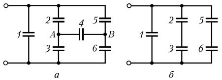
Example 12.7. Capacitors with capacitances C are each connected as shown in Fig.a. Determine the capacitance C total of this connection of capacitors. .
 Solution
.
If you disconnect capacitor C 4 from the circuit, you get a connection of capacitors that is easily calculated. Since the capacitances of all capacitors are the same (C 2 = C 3 and C 5 = C 6), both parallel branches are symmetrical, therefore the potentials of points A and B, equally located in the branches, must be equal. Capacitor C 4 is thus connected to points with zero potential difference. Consequently, capacitor C 4 is not charged, i.e. it can be eliminated and the diagram presented in the problem statement simplified (Fig.b).
Solution
.
If you disconnect capacitor C 4 from the circuit, you get a connection of capacitors that is easily calculated. Since the capacitances of all capacitors are the same (C 2 = C 3 and C 5 = C 6), both parallel branches are symmetrical, therefore the potentials of points A and B, equally located in the branches, must be equal. Capacitor C 4 is thus connected to points with zero potential difference. Consequently, capacitor C 4 is not charged, i.e. it can be eliminated and the diagram presented in the problem statement simplified (Fig.b).
This diagram is from three parallel branches, two of which contain two series-connected capacitors
![]()
Answer: Ctot = 2C.
Example 12.7.Flat air condenser capacitance C 1 = 4 pF is charged to a potential difference U 1 = 100 V. After disconnecting the capacitor from the voltage source, the distance between the capacitor plates was doubled. Determine: 1) the potential difference U 2 on the capacitor plates after they are moved apart; 2) the work of external forces to move the plates apart.
Given: C 1 =4pF=4∙10 -12 F; U 1 =100V; d 2 =2d 1.
Find: 1)U 2 ; 2) A.
Solution. The charge of the capacitor plates does not change after disconnection from the voltage source, i.e. Q=const. That's why
C 1 U 1 = C 2 U 2, (1)
where C 2 and U 2 are, respectively, the capacitance and potential difference on the capacitor plates after they are moved apart.
Considering that the capacitance of a flat capacitor is , from formula (1) we obtain the required potential difference
![]() (2)
(2)
After disconnecting the capacitor from the voltage source, the system of two charged plates can be considered as closed, for which the law of conservation of energy is satisfied: the work A of external forces is equal to the change in the energy of the system
A= W 2 - W 1 (3)
where W 1 and W 2 are the energy of the capacitor field in the initial and final states, respectively.
Taking into account that and (q – const), from formula (3) we obtain the required work of external forces
[Taking into account that q=C 1 U 1 and formula (2)].
Answer: 1) U 2 =200V; 2) A=40nJ.
Example 12.7.A solid ball of dielectric with radius R=5cm is charged uniformly with a volume density ρ=5nC/m 3 . Determine the energy of the electrostatic field contained in the space surrounding the ball.
Given: R=5cm=5∙10 -2 m; ρ=5nC/m 3 = 5∙10 -9 C/m 3.
Find: W.
Solution. The field of a charged ball is spherically symmetrical, therefore the volumetric charge density is the same at all points located at equal distances from the center of the ball.
 Energy in an elementary spherical layer (it is chosen outside the dielectric, where the energy should be determined) with a volume dV (see figure)
where dV=4πr 2 dr (r is the radius of the elementary spherical layer; dr is its thickness); ![]() (ε=1 – field in vacuum; E – electrostatic field strength).
(ε=1 – field in vacuum; E – electrostatic field strength).
We will find the tension E by Gauss's theorem for a field in a vacuum, and mentally choose a sphere of radius r as a closed surface (see figure). In this case, the entire charge of the ball, creating the field under consideration, gets inside the surface, and, according to Gauss’s theorem,

Substituting the found expressions into formula (1), we obtain
![]()
The energy contained in the space surrounding the ball is
Answer: W=6.16∙10 -13 J.
Example 12.7.A flat capacitor with an area of plates S and a distance between them ℓ is given a charge q, after which the capacitor is disconnected from the voltage source. Determine the force of attraction F between the capacitor plates if the dielectric constant of the medium between the plates is ε.
Given: S; ℓ; q; ε.
Find: F.
Solution. The charge of the capacitor plates does not change after disconnection from the voltage source, i.e. q=const. Let us assume that, under the influence of the attractive force F, the distance between the plates of the capacitor has changed by d ℓ . Then the force F does work
According to the law of conservation of energy, this work is equal to the loss of energy of the capacitor, i.e.
Substituting the expression for the capacitance of a flat capacitor into the formula for the energy of a charged capacitor, we obtain
Answer:
Example 12.7.A flat capacitor with an area of plates S and a distance between them ℓ is connected to a constant voltage source U. Determine the force of attraction F between the plates of the capacitor if the dielectric constant of the medium between the plates is ε.
Given: S; ℓ; U; ε.
Find: F.
Solution. According to the conditions of the problem, a constant voltage is maintained on the capacitor plates, i.e. U=const. Let us assume that, under the influence of the attractive force F, the distance between the plates of the capacitor has changed by dℓ. Then the force F does work
According to the law of conservation of energy, this work in this case goes to increase the energy of the capacitor (compare with the previous task), i.e.
from where, based on expressions (1) and (2), we obtain
Substituting the expression for the capacitance of a flat capacitor into the formula for the energy of a capacitor, we obtain
Substituting the energy value (4) into formula (3) and performing differentiation, we find the desired force of attraction between the capacitor plates
 .
.
where the "-" sign indicates that the force F is an attractive force.
 (1 ratings, on average: 5,00 out of 5)