Conditions for symmetry of a three-phase electricity consumer. Three-phase electrical circuits
Three-phase electrical circuits are very common, as they have a number of advantages compared to single-phase, as well as circuits direct current. In this article we will look at the concept of a three-phase electrical circuit, as well as its advantages over others.
Three-phase circuit concept
So, a three-phase electrical circuit is a circuit in the branches of which there are three EMFs varying in time according to a harmonic law (sinusoidal law) with the same frequency, but having a phase shift relative to each other by an angle equal to 2π/3 (120 0).
To obtain a three-phase harmonic signal, three-phase synchronous generators are used, in the three stator (armature) windings of which these EMFs are induced.
With the positive directions of the EMF indicated in the figure below (from the ends of the phases x, y, z to their beginnings a, b, c):
The emf will change according to the expressions below:
Below are graphs of changes in these values over time:

When combining the EMF vector E a with the axis of real values of the complex plane:
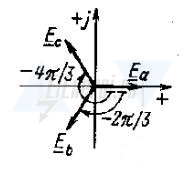
We obtain expressions for the EMF presented in complex form:
It should also be noted that the emf E a is usually directed upward vertically when constructing vector diagrams, which, in turn, corresponds to a rotation of the complex plane by 90 0 counterclockwise. In this case, the axes of imaginary and real quantities may not be indicated:

Using the positive direction and having information about the laws of change in EMF or having the corresponding graphs, you can determine the actual directions and instantaneous values of the EMF at any time. So, for example, at t = 0, e a = 0, a:
In the case where e b< 0, а e c >0, then at t = 0 the emf e c and e b will be directed in different directions.
If you look at graph b), which shows a three-phase harmonic signal, you can see that phase A will reach its maximum value first, then phase B, and only then phase C. This sequence of phases reaching their maximum (amplitude) values is called a direct sequence of alternation phases If the rotor synchronous generator rotated in the opposite direction, then the phase alternation would be reverse S-B-A, and this would be a reverse phase sequence. It is this sequence that directly determines the direction of rotation of both three-phase asynchronous electric machines and three-phase synchronous machines. Calculations and analysis of three-phase circuits are usually carried out under the assumption that the system has direct phase rotation.
Symmetrical and unbalanced three-phase systems
A system of three EMFs will be called symmetrical if all three phase voltages and currents have the same effective values, have a shift relative to each other by an angle of 2π/3 or 120 0.
The system will be called asymmetrical if the effective values of currents and voltages are not equal or the phase shift angle is not equal to 2π/3 or 120 0.
Synchronous three phase generators have just a symmetrical EMF system.
Power supply to consumers from a three-phase power supply system
In very rare cases, electrical energy consumers are supplied directly from generators. Such systems are used only in cases of emergency power outage (diesel generators or gasoline generators) or in places where extending power lines is not economically feasible.
Therefore, for the most part, consumers of electrical energy receive their power from secondary windings transformers, which, like generators, also have an almost symmetrical EMF system. Therefore, as a rule, it is rarely taken into account how the EMF is created at the load - by transformers or generators.
Not only three-phase consumers, but also single-phase ones, and also, for the most part, DC consumers (through controlled or uncontrolled rectifiers) receive power from three-phase electricity sources.
Also three phase receiver electrical energy can be considered as a device that consists of three two-terminal networks having the same parameters, which are connected to each wire of a circuit between which there are voltages shifted in phase relative to each other by an angle equal to 2π/3 or 120 0. Each two-terminal network is called a network phase alternating current. The most common three-phase consumers are asynchronous electric motors, electromagnets, electric furnaces.
A single-phase electricity receiver can be considered as an ordinary two-terminal network, which is designed to be connected to two network wires and has one voltage, unlike a three-phase one. Single-phase electrical receivers include lighting lamps, asynchronous electric motors low power, household electrical appliances and other devices.
Advantages of three-phase systems
Unlike single-phase, three-phase systems have a number of advantages, namely:
- It is the three-phase system that makes it possible to obtain a rotating magnetic field, which allows the use of three-phase asynchronous electric motors;
- Improves the technical and economic performance of transformers and generators;
- Simplifies the system for generating and transmitting electrical energy from the generator to the consumer;
- Allows you to connect to the network electrical receivers designed for different voltage ratings (linear and phase);
Three-phase systems are most widespread. Electric Energy, developed on power stations, is delivered and distributed among consumers in the form of three-phase alternating current energy.
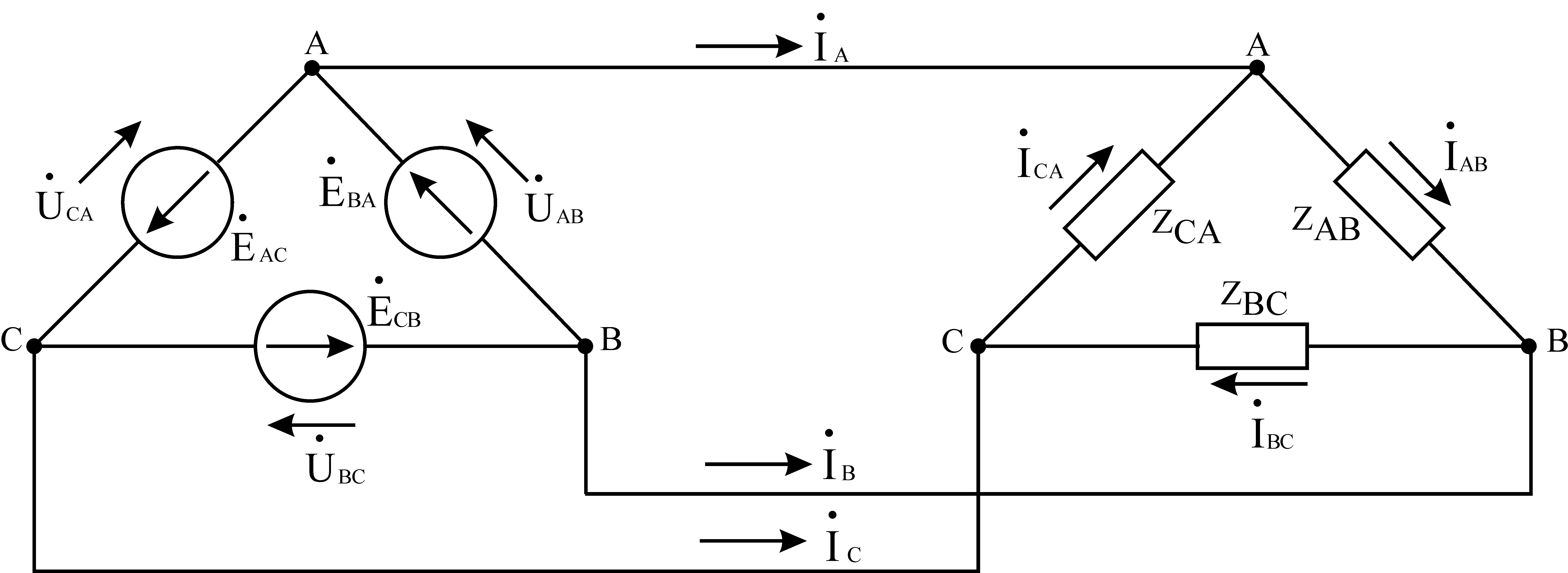
If the end of each phase of the generator winding is connected to the beginning of the next phase, a delta connection is formed. Three line wires leading to the load are connected to the winding connection points.
In Fig. Figure 5 shows a three-phase circuit connected by a delta. As can be seen from Fig. 5, in three-phase circuit connected by a triangle, phase and line voltages are the same Uл = Uф
Rice. 5. Three-phase delta-connected circuit
Linear and phase load currents are related to each other by Kirchhoff’s first law for nodes a, b, c:

Hence, at symmetrical load Il = √3 Iph
Three-phase star-connected circuits have become more common than three-phase delta-connected circuits. This is explained by the fact that, firstly, in a circuit connected by a star, two voltages can be obtained: linear and phase. Secondly, if the winding phases electric machine connected by a triangle are in different conditions, additional currents appear in the winding, loading it. Such currents are absent in the phases of an electric machine connected in a star configuration.
3.2 Calculation of symmetrical operating modes of three-phase circuits
Three-phase circuits are a type of sinusoidal current circuits, and, therefore, all previously discussed methods of calculation and analysis in a complex form fully apply to them.
A three-phase receiver and a three-phase circuit in general are called symmetrical , if in them complex resistances corresponding phases are the same , i.e. Z A = Z B = Z C . Otherwise they are asymmetrical . Equality of modules specified resistances is not sufficient symmetry condition chains. So, for example, the three-phase receiver in Fig. 6 is symmetrical, and in Fig. 7 – no.

Rice. 6. Fig. 7.
If a symmetrical three-phase generator voltage system is applied to a symmetrical three-phase circuit, then a symmetrical current system will take place in it. This mode of operation of a three-phase circuit is called symmetrical
.
In this mode, the currents and voltages of the corresponding phases are equal in magnitude and are shifted in phase with respect to each other by an angle  . As a result of this, the calculation of such circuits is carried out for one phase, which is usually taken to be the phase A
. In this case, the corresponding quantities in other phases are obtained by formally adding the phase variable to the argument A
phase shift while keeping its module unchanged. So for the symmetrical operating mode of the circuit in Fig. 8
. As a result of this, the calculation of such circuits is carried out for one phase, which is usually taken to be the phase A
. In this case, the corresponding quantities in other phases are obtained by formally adding the phase variable to the argument A
phase shift while keeping its module unchanged. So for the symmetrical operating mode of the circuit in Fig. 8

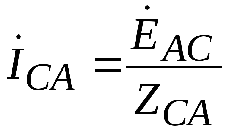
with known line voltage and phase resistances Z AB = Z BC = Z CA = Z can be written

where the phase shift angle φ between voltage and current is determined by the nature of the load Z.
Then, based on the above, the currents in the other two phases are equal:
Complexes of linear currents can be found using a vector diagram, from which it follows
![]()
![]()
An example of calculating the symmetrical operating mode of a three-phase circuit is given in Appendix 3.
4. Electrical circuits of periodic non-sinusoidal current
Periodic non-sinusoidal currents and voltages in electrical circuits arise in the case of the action of non-sinusoidal EMFs in them or the presence of nonlinear elements in them. Real EMF, voltages and currents in electrical circuits of sinusoidal alternating current differ from a sinusoid for various reasons. In the energy sector, the appearance of non-sinusoidal currents or voltages is undesirable, because causes additional energy losses. However, there are large areas of technology (radio engineering, automation, computer technology, semiconductor converter technology), where non-sinusoidal quantities are the main form of EMF, currents and voltages.
Let us consider brief theoretical information and methods for calculating linear electrical circuits when exposed to sources of periodic non-sinusoidal EMF.
4.1. Expansion of a periodic function into a trigonometric series
As is known, any periodic function that has a finite number of discontinuities of the first kind and a finite number of maxima and minima during the period
can be expanded into a trigonometric series (Fourier series):
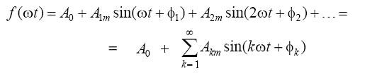
The first term of the series is called constant component , second term – fundamental or first harmonic . The remaining members of the series are called higher harmonics .
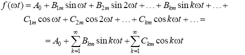
If we expand the sines of the sum of each of the harmonics in the expression, then it will take the form:
In the case of analytical specification of the function f (ωt) series coefficients can be calculated using the following expressions:
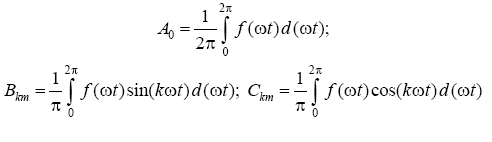
After which the amplitudes and initial phases of the harmonic components of the series are calculated:

The Fourier series coefficients of most periodic functions encountered in technology are given in reference data or in textbooks on electrical engineering.
Three-phase current circuits
Multiphase and three-phase systems. The principle of obtaining three-phase EMF
A multiphase power source is a set of EMFs of the same frequency, shifted relative to each other in phase. The combination of a multiphase source and a multiphase receiver forms a multiphase electrical circuit. The individual electrical circuits that make up a multiphase system are called phases. Thus, phase is a twofold concept. On the one hand, this is a stage of a periodic process, on the other hand, it is part of a multiphase electrical circuit.
If the number of phases is m=3, we get a three-phase system. The three-phase system is the main one for power supply to enterprises. Thanks to its technical and economic characteristics, three-phase current provides the most economical transmission of electrical energy and allows the creation of simple, reliable and economical transformers, generators, and electric motors.
Fundamental research that led to implementation three-phase systems were made by Nikola Tesla (origin - Austria-Hungary, now - Croatia) and the Russian scientist Dolivo-Dobrovolsky.
Major inventions related to three-phase power supply systems were made and patented by Tesla. At the same time, the work of Dolivo-Dobrovolsky, who was the first to use three-phase current for industrial purposes, is of great theoretical and practical importance. All links of the three-phase circuit: transformers, generators, transmission lines and motors were developed by M.O. Dolivo-Dobrovolsky so deeply that they have not fundamentally changed to this day.
In some technical devices, two-phase, four-phase, and six-phase systems are used.
A three-phase EMF system is obtained in three-phase generators. Such a generator consists of a stator and a rotor. Three windings are placed in the stator slots, shifted relative to each other in space by 120°. The rotor is made in the form of a permanent magnet or electromagnet. When it rotates, an EMF is induced in the windings, the graphs of instantaneous values of which are presented in Fig. 1
All EMFs of the considered system have equal amplitudes E m and are shifted relative to each other in phase by an angle of 120°. Such an EMF system is called symmetrical.
Three-phase symmetrical system
Taking the reference point at the moment when е a =0, we write down the instantaneous values of all emfs.
e L1 =E m *sinω t
e L2 =E m *sin (ω t-120° )
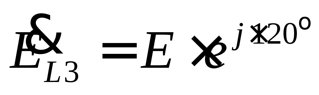
e L3 =E m *sin (ω t-240° )=E m *sin (ω t+120)
In symbolic form (as complex amplitudes):
 ,
,
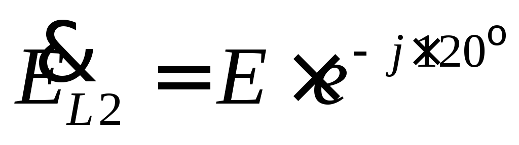 ,
,
 , Where
  .
.
Vector diagram symmetrical three-phase system is shown in Fig. 2.

A symmetrical three-phase system has the following properties:
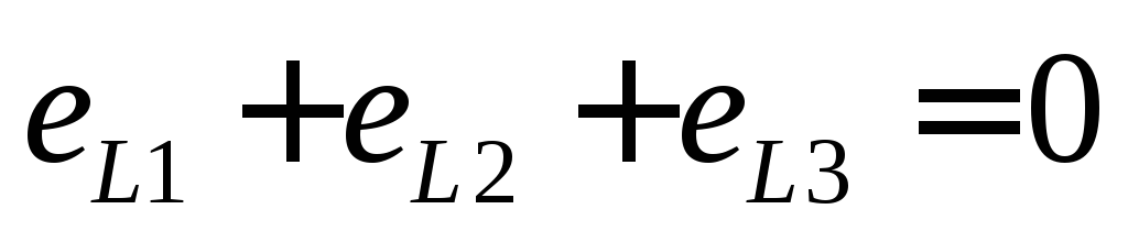 ,
,
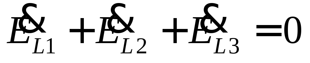 .
.
This property is also true for currents with a symmetrical load.
Types of three-phase circuit connections .
There are two main types of connection of the windings of transformers, generators, and receivers in three-phase circuits: star connection and delta connection.
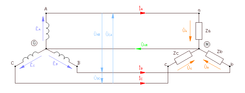
The star connection between the source and receiver is shown in Figure 3.
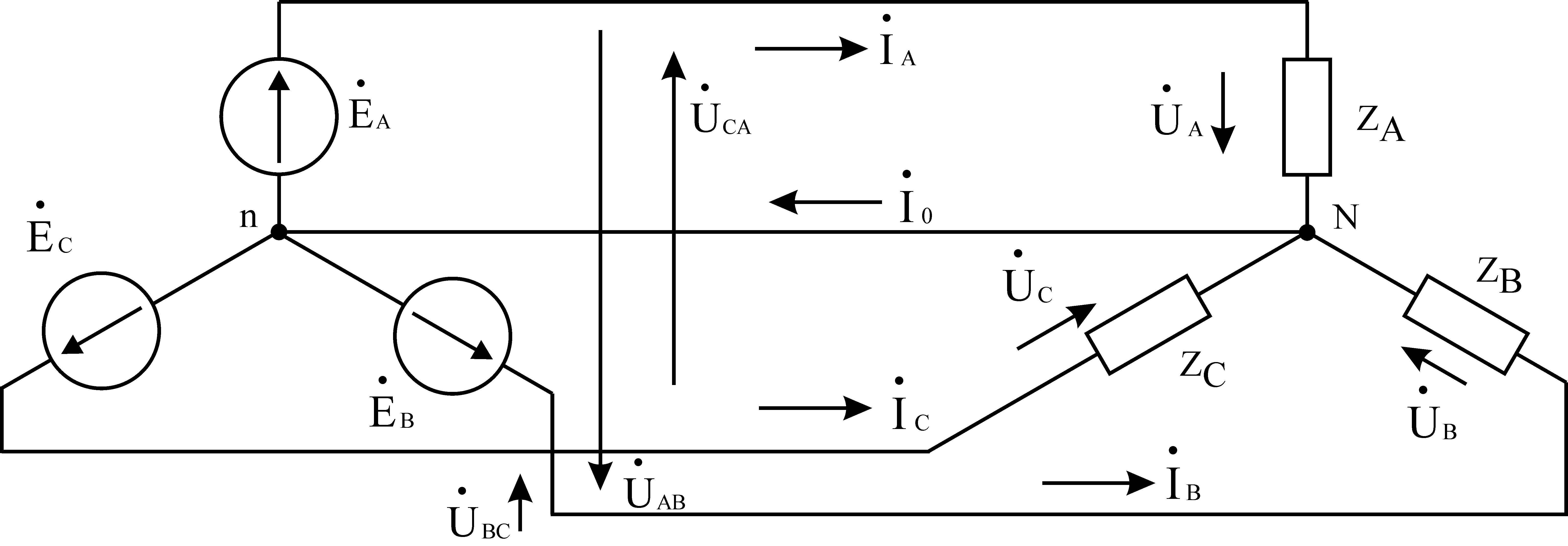
The voltages at the terminals of individual phases of the receiver or source are called phase voltages.  - phase voltages. The voltages between the line wires connecting the three-phase source to the receiver are called line voltages.
  - linear voltages. Currents flowing in the phases of the receiver or generator are called phase currents. Currents flowing in linear wires are called linear currents. Obviously, for a star connection the line currents
  are phase currents. The wire connecting the zero nodes of the source and receiver (nodes n, N) is called the zero (common, neutral) wire. According to Kirchhoff's current law, the current in the neutral wire is equal to
 .
.
With a symmetrical load, the currents in the phases are equal. Then
=
the current in the neutral wire will be zero. Therefore, with a symmetrical load, the source and load can be connected by only three linear wires.
In Fig. Figure 4 shows a vector diagram of the circuit in symmetrical mode and the active-inductive nature of the load, in which the currents lag behind the voltages.

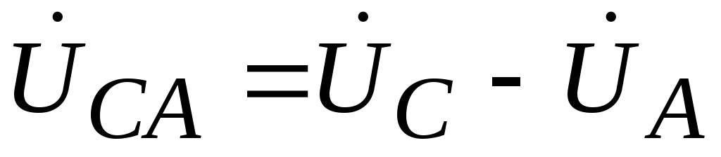
Let us establish the relationship between linear and phase voltages. Line voltages are defined as the differences in phase voltages.
 ;
;
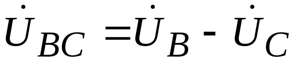 ;
; .
.
From the isosceles triangle ANB it follows
 .
.
In Fig. Figure 5 shows a triangle connection between source and receiver.
With this type of connection, phase EMFs are connected in series. The common points of each pair of phase EMFs and the common points of each pair of receiver branches are connected by linear wires. At first glance, such a connection of phase EMF is an emergency short-circuit mode. However, we should not forget that the sum of the instantaneous values of the EMF of a three-phase symmetrical source at any time is zero.
In Fig. Figure 6 shows vector diagrams of voltages and currents in symmetrical mode and an active-inductive load for a delta connection.

Linear currents are defined as the differences in phase currents:
 ;
;
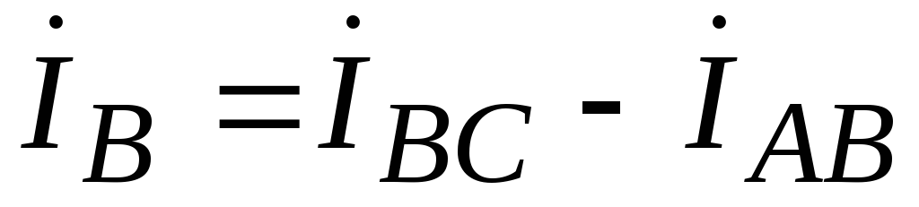 ;
; .
.
Wherein:
 ;
;
 .
.
Calculation of three-phase circuits with an asymmetric load.
The calculation of a three-phase circuit when connecting a source to a receiver in a triangle does not contain anything fundamentally new compared to the calculation of a conventional sinusoidal current circuit. In the circuit in Fig. 5 we find phase currents:
 ;
;
 ;
; .
.
Based on the found phase currents, we determine line currents based on Kirchhoff's current law:
;
;.
A three-phase circuit is calculated similarly when the source and receiver are connected by a star with a neutral wire (Figure 3). According to Ohm's law we determine phase currents:
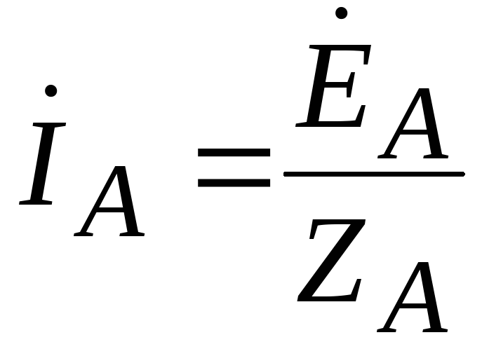 ;
;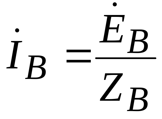 ;
;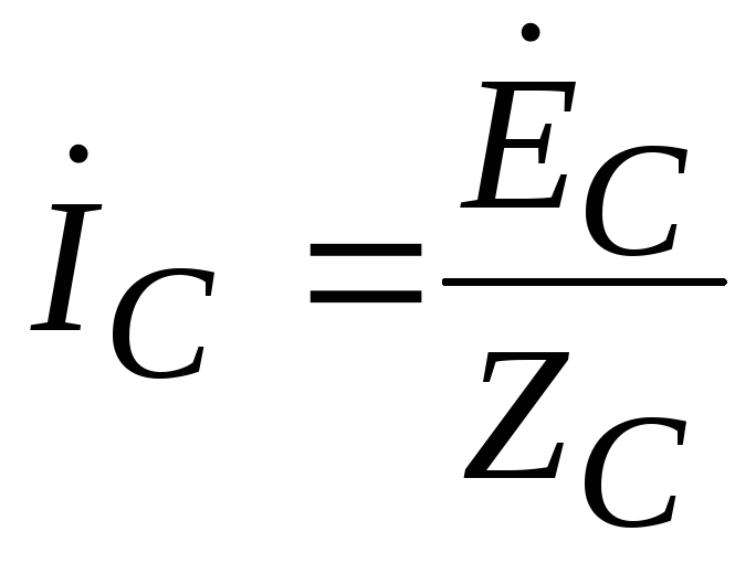 .
.
The phase currents for a star connection are linear currents. The current in the neutral wire is determined according to Kirchhoff's current law:
.
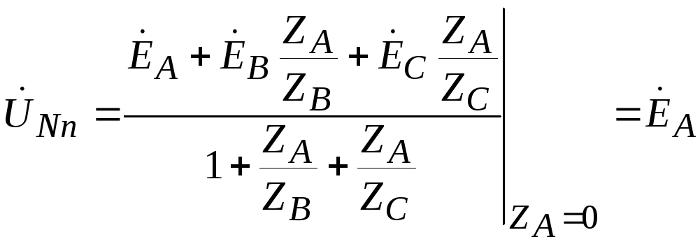
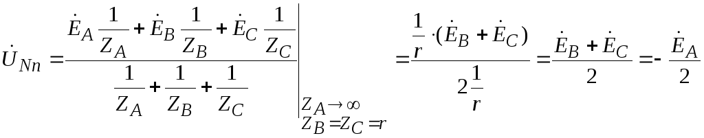
To calculate an asymmetrical three-phase circuit when connected by a star with a three-wire line, we use the two-node method.
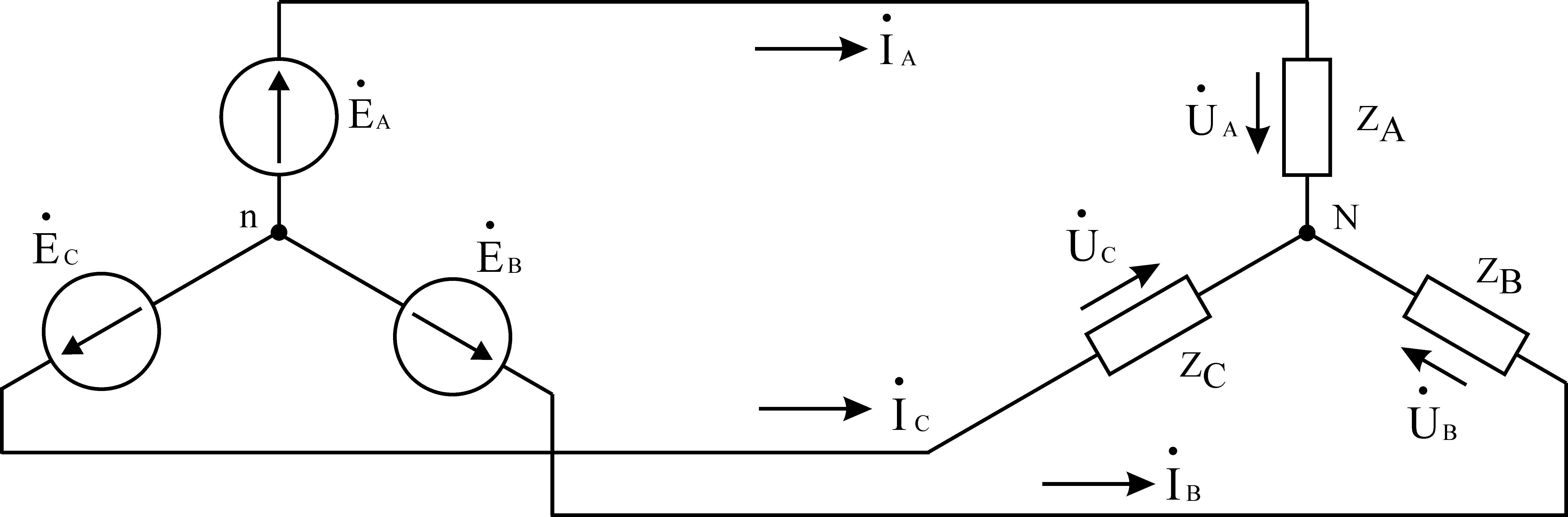
Rice. 7
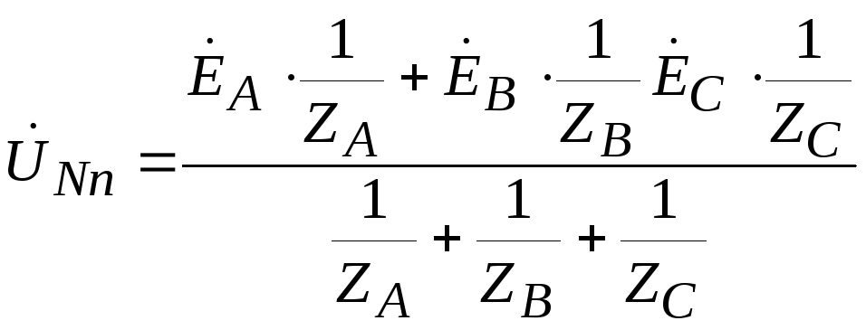
Let's determine the voltage between the zero points of the source and load -  , which is called the neutral bias voltage.
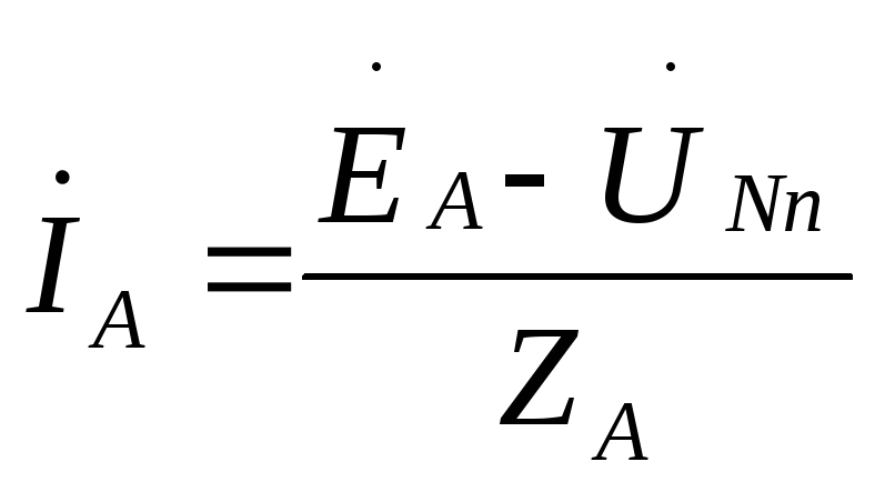
Knowing the tension  , let’s determine linear (aka phase) currents according to Ohm’s law for the section of the circuit with EMF:
=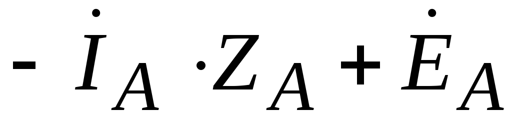 ,
,
 .
.
Likewise


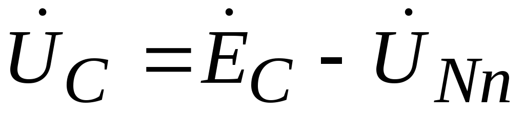
The voltage at the load phases will be equal to:
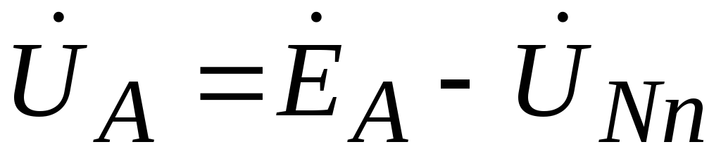 ,
,
 ,
,
 .
.
Let's consider two special cases of asymmetric load.
1) Short circuit of one of the load phases with equal resistance in the other two phases.
 ,
,
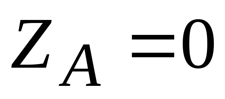 .
.
Neutral bias voltage we determine by a well-known expression, having previously multiplied its numerator and denominator by  .
.
 ,
,
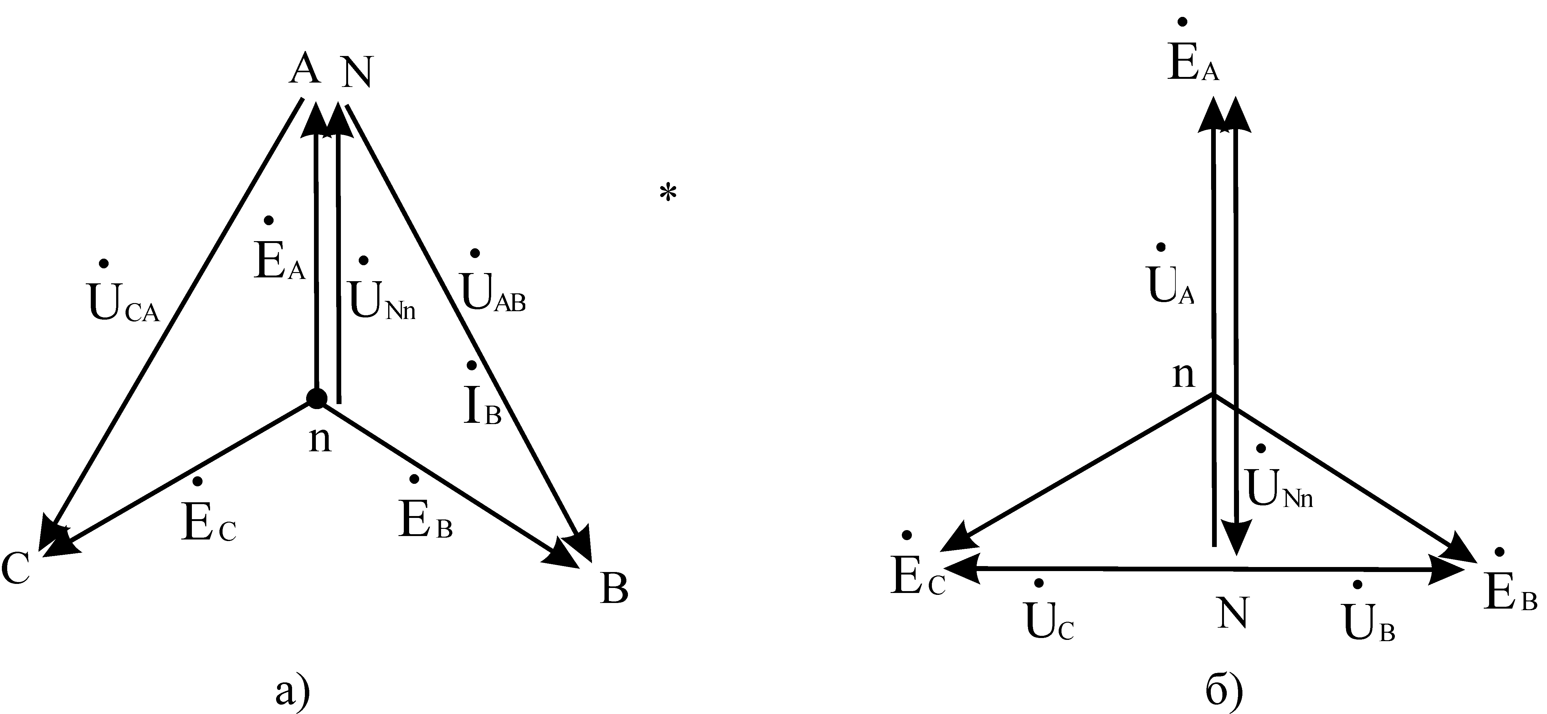
Thus, during a short circuit, the load is in phase A, the voltage on it becomes zero, and the voltages on the phases IN And WITH the loads increase to linear, i.e. V  once. The neutral bias voltage for this case will be equal to the phase voltage. The vector diagram for this case is shown in Fig. 8a.
2) An open circuit in one of the load phases with equal resistance in the other two phases.
 ,
,
 .
.
The neutral bias voltage for this case will be equal to:
The voltages at the load phases will be equal to:
,
,
Thus, in the event of a phase failure A load, the voltage in it becomes 1.5 times greater than the phase voltage, the voltage on the phases IN And WITH the loads decrease and become equal to half the line voltage, the neutral bias voltage becomes equal to half the phase voltage.
The vector diagram for this case is shown in Fig. 8b
7.5.Power in a three-phase circuit and its measurement.
Considering that for a symmetrical three-phase star-connected circuit  ,
, , and for connected by a triangle
  ,
, , we get, regardless of the type of connection
Where  - phase shift between phase voltage and phase current (cosφ – power factor).
Similarly, for reactive and apparent powers with a symmetrical load, we obtain:
In the case of an asymmetrical load, the powers are calculated for each of the load (source) phases separately and then added up.
To measure power in a four-wire three-phase circuit connected by a star, wattmeters are connected according to the diagram shown in Fig. 7.9.

The total power consumed by the load will be equal to the sum of the readings of three voltmeters connected to the phases A, B And WITH. In a three-wire circuit, two wattmeters are used, connected according to the diagram shown in Fig. 7.10.
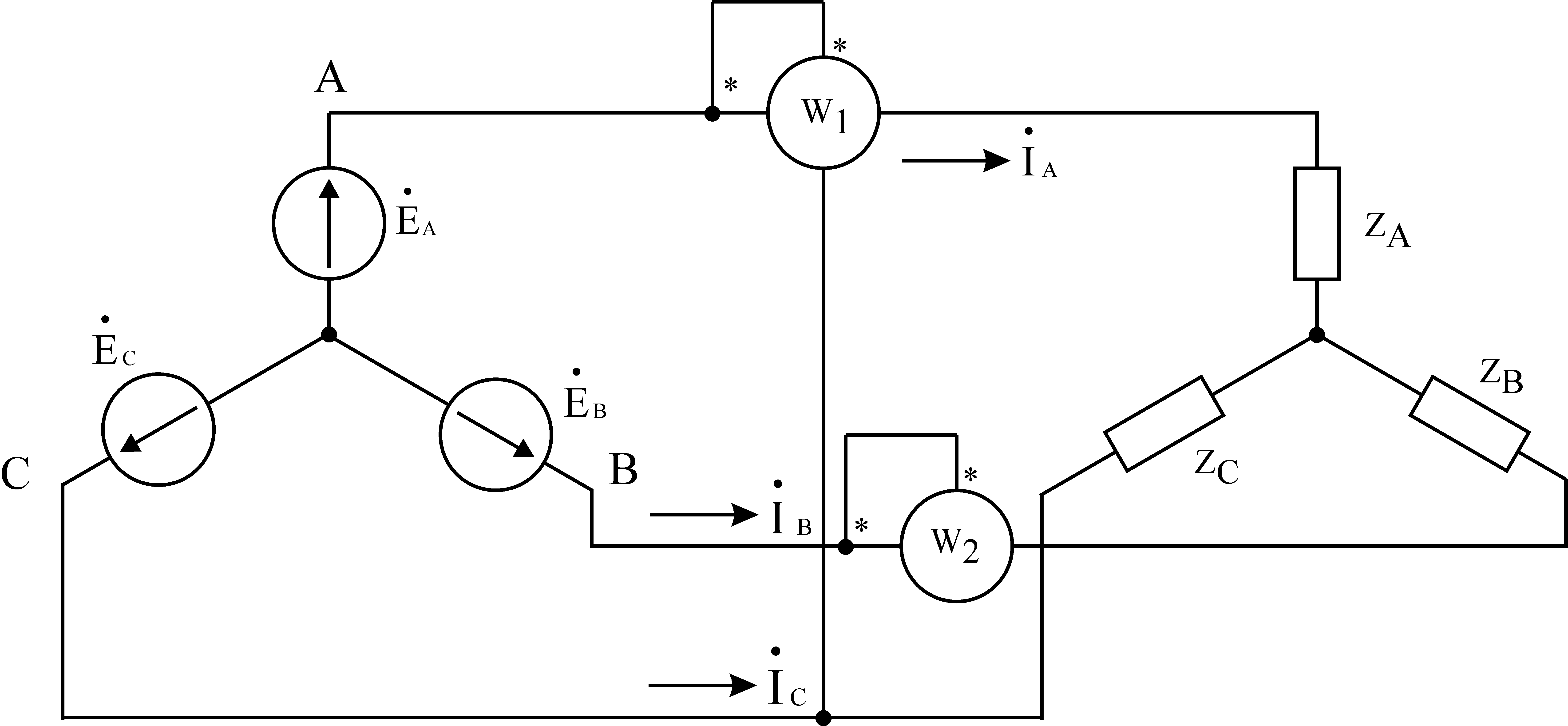
Let us show that the power displayed by two wattmeters will be equal to full power three-phase circuit (the so-called two-wattmeter circuit, or Aaron's circuit).
The outstanding Russian engineer-inventor Mikhail Osipovich Dolivo-Dobrovolsky, in addition to the asynchronous motor, invented three-phase electrical network , which could power such an engine.
A three-phase system consists of three separate electrical circuits in which sinusoidal EMFs of the same frequency operate, which in turn are shifted from each other by 120°, and created by one energy source. The energy source is most often a three-phase generator.
The advantage of a three-phase circuit is its balance. That is, the total instantaneous power three-phase circuit remains constant throughout the entire EMF period.
A three-phase alternating current generator has three independent windings, which are shifted among themselves by an angle of 120°. Just like the windings, the initial phases of the EMF are shifted by 120°. The equations describing the change in EMF in each of the windings are as follows:
The vector diagram of the EMF at the initial moment of time represents three vectors, the length of which is equal to amplitude value EMF Em, and the angle between them is 120°. If you rotate the vectors counterclockwise, relative to the fixed axis, then they will pass in the order Ea, Eb, Ec, this order is called straight sequence.

Essentially, each individual phase could be connected separate wires, but in this case the result would be a six-wire disconnected system. This would be extremely unprofitable from an economic point of view, because, after all, it would be an overconsumption of material. In order to avoid this, connected connection systems were invented.
Star connection
When the windings are connected in a star, all three phases have one common point- zero. Moreover, such a system can be three-wire or four-wire. In the latter case it is used neutral wire. A neutral wire is not needed if the system is symmetrical, that isthe currents in the phases of such a system are identical. But if the load is asymmetrical, then the phase currents are different, and a current appears in the neutral wire that is equal to the vector sum of the phase currents
![]()
Also, the neutral wire can act as one of the phases; if it fails, this will prevent failure of the entire system. However, it must be taken into account that the neutral wire is not designed for such loads, and in order to save metal and insulation, it is manufactured for lower currents than in the phases.

In three-phase circuits there are so-called phase and linear voltages and currents.
Phase voltage is the potential difference between the zero point and the line wire. That is, simply put, phase voltage is the voltage on a phase.
Line voltage is the potential difference between line wires.

When connected by a star, the phase and line voltages are related as
![]()
And phase and linear currents with a symmetrical load are the same
Thus, we can conclude that in a symmetrical three-phase circuit, when the phases are connected by a star, the voltages differ from each other by a factor of 1.72, and the linear and phase currents are equal.
Delta connection
In a delta connection, the end of one winding is connected to the beginning of another. Thus, a closed loop is formed.
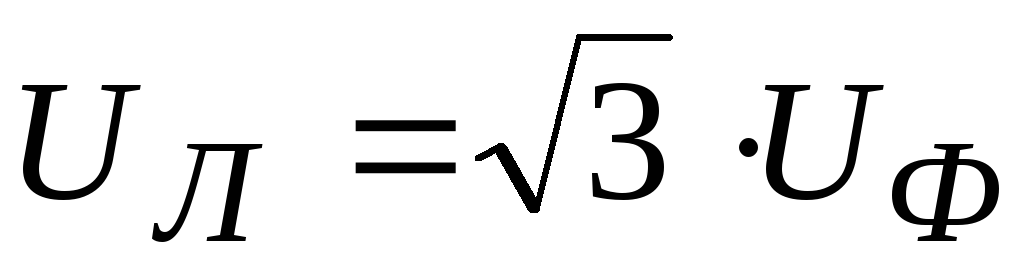
 In such a connection, each phase is under linear voltage, that is, linear and phase voltages are equal
![]()
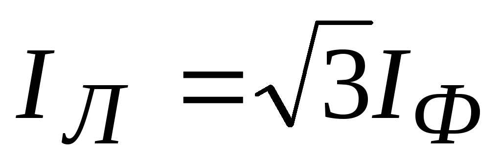
And phase and linear currents are related as
![]()
In a similar way, we draw a conclusion for a triangle connection: in a symmetrical three-phase circuit, when the phases are connected by a triangle, the currents differ from each other by 1.72 times, and the linear and phase voltages are equal.
 (1 ratings, on average: 5,00 out of 5)

