Current program for calculating short circuit currents. Construction of a new network based on the equivalent. Calculation of electrical quantities at the location of damage
In this article, I want to introduce you to the "Emergency Emergency" program version 3.0.8. For those who don't know, this program is designed for calculating currents short circuit in networks up to 1000 V. There is a paid and free version. The paid version costs 15,000 rubles, in principle you can use the free version, if you use the free version, you will not be able to calculate short-circuit currents when supplying consumers with electricity from an autonomous generator and you cannot export the calculation results to separate file. As practice has shown, you can also use the free version. To get better acquainted with the "Emergency Emergency" program, let's look at an example of calculating TKZ.
Types of failures in industrial electrical systems. The importance of grounding the electrical system. Application of results 1 Comparison of results across bars and boards. 2 Comparison of results with medium and high voltage switches. 3 Comparison of results with low voltage switches. 4 Comparison of results with fuses.
This course is designed to teach the principles and methods of short circuit calculations. rather than using special software. Purpose: Switches, fuses and protective devices in general constitute a part. fundamental of electrical systems because they provide protection in two senses.
Calculation example
Fundamental electrical diagram is shown in Fig. 1.
The power source can be a diesel power plant or a district network that supplies consumers through a step-down transformer. It is necessary to check the protection devices for disconnecting the short circuit at points K-1 and K-2 within the standard time.
For point K-1, the protection devices are circuit breaker, installed at the generator output in the diesel power station container, and fuses installed in the distribution panel of the transformer substation.
Personnel Invest in existing equipment and avoid unexpected investments. For this reason, the purpose of this course is to provide participants with basic knowledge. be able to understand and solve practical problems related to coordination. Overcurrent protection in industrial and commercial electrical installations.
Duration: the course consists of 2 sessions of 6 hours each. Protection limits 1 Transformers 2 Motors 3 Cables. Defense coordination process. 1 Basic information 2 Graphic time graphs. 3 Enabling restrictions 4 Analyzing results Do devices protect commands? Is there coordination between devices?
For point K-2, the protection device is a circuit breaker installed in the ASU-AVR panel on the MA1 line feeder.
All data necessary for the calculation is given on schematic diagram(see Fig. 1).
Point K-1 (G)
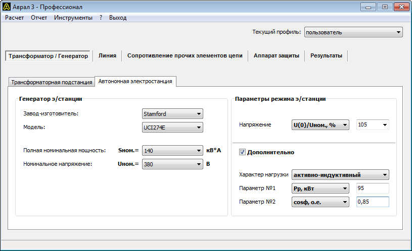
Calculation of the emergency short circuit mode and determination of the activation of the protection device at point K-1 when consumers are powered from diesel power plant(generator). All initial data and calculation results are presented in the program screenshots, see Fig. 2-6.
Final conclusions and comments. This course is designed to teach the principles and techniques of coordination. protection rather than using special software. Purpose: It is very important to identify any electrical system in accordance with current regulations. risks that may be caused by an electric arc and thus are accepted. appropriate measures.
Duration: The course is distributed in 1 session of 5 hours. What elements are needed to determine the level of risk from an electric arc. Type of equipment Protective devices Voltage levels at which it is applied Effects of contribution sources. Interpreting the results How to use the results What to do to implement a security program.


Point K-2 (G)
Calculation of the emergency short circuit mode and determination of the activation of the protection device at point K-2 when consumers are supplied from a diesel power plant (generator). All initial data and calculation results are presented in the program screenshots, see Fig. 7-10. Since entering the DES parameters is similar to calculating the K-1 (G) point, this screenshot is not shown here.
Ways to reduce the level of risk from electric arcs. Equipment that can help alternatives for system operation. This course is designed to teach the principles and techniques of hazard calculations. electric arc, rather than using special software.
Purpose: This course is focused on confirming knowledge in the field of systems analysis. Electrical and solve various practical problems using specialized software. The course is designed to enable participants to... Prove your knowledge of element modeling. Perform load flow studies. Calculation and application of fault studies. Defense analysis and coordination.


Point K-1 (T)
Calculation of the emergency short circuit mode and determination of the operation of the protection device at point K-1 when consumers are supplied from a centralized network (transformer). All initial data and calculation results are presented in the program screenshots, see Fig. 10-15.
Agenda This course is for us. Network installation of the program Server value Users Creating user accounts. Data manager functions. Types and elements Example definition. Element palette Buses Substations Elements. Elements Modeling Generators Linear lines Cables Loads Motors Capacitors Transformers.
Creation of scenarios and case studies. Study of load flows. Element considerations. Transformers. Rush generators. Loads. Engines. Calculation parameters. Results. Unified text tables. Vector diagrams. Enable secondary controls. Inclusion of demand curves. Managing unbalanced networks.


Point K-2 (T)
Calculation of the emergency short circuit mode and determination of the operation of the protection device at point K-2 when consumers are supplied from a centralized network (transformer). All initial data and calculation results are presented in the program screenshots, see Fig. 16-19. Since entering the transformer parameters is similar to calculating the K-1 (T) point, this screenshot is not shown here.
Calculation of electrical quantities at the location of damage
Protection in electrical systems. Protection limits Transformers Motors Cables. The main problem with rewinding a transformer is calculating the diameter of the wire, somewhere the current density is 2A square meters, elsewhere 3A, and therefore does not fully utilize the magnet's power. Therefore, the diameter can be calculated from the size of the coil window. Then we determine the height of the winding to the middle of the window and divide it by the approximate diameter of the wire and find the number of layers, then divide the length of the diameter and find the coils of 1 layer and multiply them by the number of layers and get the total number of turns.


Calculation results
According to the calculation results, the protection devices operate within the standard time when a short circuit occurs at points K-1 and K-2. At the same time, the operation of protection devices in emergency mode was tested when consumers were powered both from a diesel power plant and from a centralized network.
If the windings are more than rated, select a thicker wire and repeat the calculation until they are assembled. This is an insulated diameter, and with the new standards it is double. To measure the actual diameter, open the wire with a blade and twist it tightly 10 turns onto the pencil. Using a ruler, we measure the length of the layer and divide the turns. The measurement is more accurate with more windings. Note. Do not expose the conductor to fire, as it will weaken and the measurement will be incorrect, even detected by a normal caliper.
Designation of quantities
The report, database and calculation results of the program use symbols physical quantities. Below is full list their designations.
Transformer
- Uinn.nom., kV – Rated voltage high voltage windings;
- Unnn.nom, V – rated voltage of the low voltage winding;
- Snom, kV*A – rated apparent power;
- Unn, V – operating mode voltage of the LV winding;
- Ik.in., kA – short circuit current at the terminals of the HV winding;
- Sk, MV*A – short circuit power at the terminals of the HV winding;
- Xс, mOhm – equivalent inductive reactance of the system;
- R1, mOhm – active resistance direct sequence;
- R0, mOhm – zero-sequence active resistance;
- X1, mOhm – positive sequence inductive reactance;
- X0 – zero sequence inductive reactance.
Generator
- Snom., kV*A – rated apparent power;
- Unom., V – rated voltage;
- f, Hz – nominal frequency;
- U(0), V – generator voltage at the time preceding the short circuit;
- Рр, kW – estimated active load power of consumers;
- Qр, kvar – calculated reactive power of consumers’ load;
- Sp, kV*A – estimated total load power of consumers;
- Iр, А – calculated load current of consumers;
- cosф, p.u. - coefficient active power consumer loads;
- tgf, p.u. – reactive power factor of consumer load;
- f, deg. – the angle between the active and total power of the load of consumers;
- Xd”, p.u. – supertransient inductive reactance along the longitudinal axis;
- Xd’, p.u. – transient inductive reactance along the longitudinal axis;
- Xd, p.u. – synchronous inductive reactance along the longitudinal axis;
- Xq”, p.u. – supertransient inductive reactance along the transverse axis;
- Xq, p.u. – synchronous inductive reactance along the transverse axis;
- X2, p.u. – negative sequence inductive reactance;
- X0, p.u. – zero sequence inductive reactance;
- R, Ohm – active resistance of the armature winding;
- Td”, s – supertransient time constant along the longitudinal axis with the armature winding short-circuited;
- Td’, s – transition time constant along the longitudinal axis with the armature winding short-circuited;
- Ta, s – decay time constant of the aperiodic component of the armature current during a three-phase short circuit at the machine terminals;
- Ks or OKZ – short circuit ratio.
Line
- Npar., pcs. – number of parallel connected conductors;
- Fphase, sq.mm. – cross-section of the phase conductor;
- Fzero, sq.mm. – cross-section of the neutral conductor;
- t start, °C – initial temperature of the conductor;
- t pr., °C – design temperature of the conductor;
- R1 linear, mOhm/m – linear positive sequence active resistance;
- R0 linear, mOhm/m – linear zero-sequence active resistance;
- X1 linear, mOhm/m – direct sequence inductive reactance per unit;
- X0 linear, mOhm/m – linear zero-sequence inductive reactance;
- R1, mOhm/m – positive sequence active resistance of the line;
- R0, mOhm/m – active resistance of the line zero sequence;
- X1, mOhm/m – positive sequence inductive reactance of the line;
- X0, mOhm/m – inductive reactance of the zero sequence of the line;
- Dav. geom., m – geometric mean distance between phase wires (only for overhead lines).
Initial conductor temperature
- Inorm.calc., A – value of the line operating current in normal mode. In the case of several parallel connected conductors, the calculated current of the entire line is indicated, and not of an individual conductor;
- t ambient normal, °C – normalized temperature value environment. As a rule, when laying a line in the ground, the value is 15 °C, in the air - 25 °C;
- t ambient, °C – ambient temperature value;
- Iadditional cont., A – reference value for a long time permissible current(permissible continuous current) of the conductor. In the case of several parallel connected conductors, the current of an individual conductor is indicated, and not the entire line;
- t additional cont., °C – reference value permissible temperature continuous (normal) mode conductor.
- t start, °C – calculated value of the initial temperature of the conductor.
Other circuit elements
- Rpr, mOhm – total active resistance of other circuit elements;
- Xpr, mOhm – total inductive reactance of other circuit elements;
- Rk.s., mOhm – active resistance of contacts and contact connections;
- Rd, mOhm – active resistance of the electric arc;
- Rр, mOhm – active resistance of the reactor;
- Xр, mOhm – inductive reactance of the reactor;
- Rav, mOhm – active resistance of the circuit breaker coil;
- Xav, mOhm – inductive reactance of the circuit breaker coil;
- Rtt, mOhm – active resistance of current transformers;
- Xtt, mOhm – inductive reactance of current transformers.
Protection apparatus
- Inom, A – rated current;
- Irast., A – rated tripping current of the release (only for the circuit breaker) according to the passport;
- Tav.,s – response time;
- Кз – safety factor;
- Iav., A – operation current taking into account the safety factor.
Calculation results
- Ip(0), A – initial (time T=0 after the occurrence of a short circuit) effective value of the periodic component of the short-circuit current.
- Ip(Tav), A – effective value of the periodic component of the short-circuit current after a period of time Tav (see below) after the occurrence of the short-circuit;
- ia(0), A – the largest initial value of the aperiodic component of the short-circuit current.
- ia(Tav), A – the value of the aperiodic component of the short-circuit current after a period of time Tav after the occurrence of the fault.
- iу, A – shock current.
- Iter.ek., A – effective value of the thermally equivalent current (see GOST 30323-95, clause 3.1.1).
- Tav., s – response time of the protection device. The value is copied into the table from the corresponding field in the Protection device group.
- Iav., A – tripping current of the protection device. The value is copied into the table from the corresponding field in the Protection device group.
I set it to a nominal value of 250A and a multiplicity of 12In, and set the response time to 5s. According to the program's calculations, the short-circuit current came out to 2.9 kA and the program issued a conclusion that the device would not work... This conclusion is NOT CORRECT!
We calculate the secondary winding in the same way to fill the second half of the window. It is important to know that it is wrong to extract additional voltages from the windings because at lower voltages the current increases, hence the thicker wire. If we need 127V, wind a coil with thick wire for current rated at 127V but 50% less full power and one coil at 93V for current rated at 220V again at 50% power and connect the two coils in series , but we should not consume a small coil as it will overheat.
You have set the operating current (without taking into account the variation in characteristics) Iav.=250*12=3000 A or 3 kA. The program only considers what you give it. Since Iokz
If you look at the time-current characteristics of the VA53-41, it will work almost instantly!
The program does not have the ability to select the type of switch, so it is strange to listen to complaints that the program “didn’t realize” that the circuit breaker should trip.
It's obvious that you made a mistake. It was necessary to enter the operating current for a time of 5 seconds, then the program would calculate correctly.
The second option with different voltages is not suitable because the transformer will receive half the power from each coil. This is how combined transformers are manufactured at the factory for different supply voltages, but they have very low efficiency and cannot provide full power, since when operating at lower voltages one part of the winding is left unusable and the workload is overloaded, the opposite is true - all coils are used at maximum voltage, but one of them is unnecessarily unusable and the other is too thin.
And in 5 seconds it will work at 2kA thermal release from a heated state.
This means that this characteristic had to be introduced, and not 250 A at a 12-fold cutoff.
Then, for the sake of interest, I slightly changed the model of my circuit so that the current would be a little more than 3 kA - and, voila! The machine began to operate at any time of operation!
Consequently, the power losses of the combined transformers are huge and their size must be increased and hence the excess energy consumption. Bad CPAs also have transformers with two coil sections, one of which there is a separation between the sections, and secondly, that the primary becomes thicker and self-inductance worsens, due to the distances of the external coils from the core, the length of the wire increases and, therefore, the active resistance. Secondary is more difficult at the bottom of the coil.
The secondary winding is wound to fill the second half of the drum, i.e. primary and secondary windings have the same area. If the secondary voltage goes higher it is good, but if it is too high to not develop from the coil as this will reduce the power, so it is properly rewound again with thicker wires when filling the window. This will measure three times when you roll up. The thicker the wire primary winding coil does not allow to reduce by 5-10%, but no more, since it will be overheated by the core of large eddy currents.
Of course, the program shows that the operation will occur within the time you specified. It should be noted that the standards indicate the maximum time for switching off the short-circuit current. Those. The shorter the response time, the better. The calculations should indicate the maximum permissible response time, in accordance with regulatory requirements. If, as a result, it turns out that the protection device will operate during this time, then regulatory requirements are being carried out.
Once again, the program does not count how long it will take for the operation to occur, but shows whether the short circuit will be disconnected within the time you specified or not.
But practice shows that new steel is not inferior to our old and crooked ones sheet metal plant, in addition, the fins are flat and tightly spaced, but they are also heated to more powerful transformers. Using used wire, we must smooth it repeatedly with a tight winding of the big drum, but not due to friction in the knee or wooden block because no matter how thick the wire is, the drainage and cross-section change. It doesn't have to be completely smooth, and if we see that it has become long and winding, there is an increased need to change it.
The conclusion suggests itself - either in the “standard” version everything is so cut down, or in principle, when calculating, you can completely ignore setting the response time for the protective device.
In the standard version, only what is indicated in the description on the website is reduced, namely:
the functions for calculating short-circuit currents when powering consumers from an autonomous power plant have been reduced, and it is also impossible to export calculation results;
Maybe with a scale to measure the weight and he can do the calculation too. It provides its customers with extensive technical and software support. This includes assistance in the use of supplied products and commissioning of complex equipment, device maintenance and many other services aimed at preventing faults and upgrading managed switchboards. The purpose of software support is to make it easier for designers, technicians, working electricians and business partners to make the most of their work.
No more, no less.
The response time in some cases is not included in the calculations. Your case is an example of this. However, this time is indicated in the table of calculation results, and the expert (inspector) can immediately see that the regulatory requirements are met.
The response time plays an important role in determining the tripping of the protection device if a change occurs effective value periodic component of the short-circuit current over time. A typical case is a short circuit in a network powered by an autonomous diesel power plant.
Also, if a fuse with a fuse link is used as a protection device, then the response time cannot be avoided here either, because The tripping current of the fuse is determined by the response time.
Of course, calculate the short circuit currents in separate parts distribution and check that the devices used have sufficient throughput short circuit. An important task for the designer is to properly design the lines and ensure their complete protection against overcurrents. There are many ways to relay parallel cables, from general overload protection to short circuit protection at the beginning of the line, to the most complex version with separate latching protection at the beginning and end of each cable.
Each of these options can be evaluated by the program. Possible failures and identify any possible problems. To others an important condition safe work electrical installation is the correct functioning of protection by automatic shutdown from the source in the event of a fault, in other words, low impedance of the fault loop so that the corresponding device can disconnect the fault within a specified time. It is then compared to the calculated fault loop resistance of the solution being solved.
I still don’t understand why, when determining the parameters of the transformer, the HV voltage can be selected only 10 kV.
The HV voltage can be selected from the one that is entered into the database for a specific transformer. The user can enter the data of the transformer with the required high side voltage and perform the short circuit calculation.
Thank you for your interest and your questions.
Using Function Keys
The calculation includes the impedance of the entire fault chain from the high voltage distribution impedance, the internal impedance of the transformer, the impedance of the current heated cables, to the internal impedance of the protective devices used. Power reliability is largely due to by selective action consecutive safety devices. Turning off only protective device,closest to the top of the fault location, the volume of the installation, disconnected from the power supply, is reduced, which reduces the economic effect caused by the power outage.
 (1 ratings, on average: 5,00 out of 5)

