DIY electronic soldering iron. How to make your own ultra-fast heating soldering iron
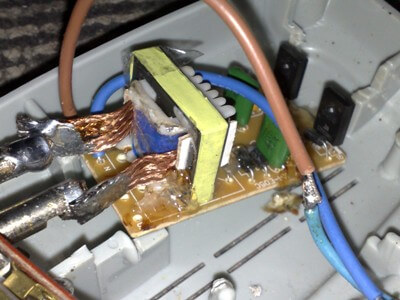
This idea was born after one good friend I made a similar soldering iron, where an ET (electronic transformer) was used to power 12 Volt halogen lamps. In fact, I didn’t come up with anything new, I just assembled a similar soldering iron using a more compact and low-power electronic transformer at 50 watts. Unlike high-power ETs, the transformer is made on an W-shaped core; winding the required winding is very inconvenient, so first you need to desolder and disassemble the transformer.
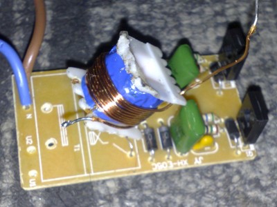
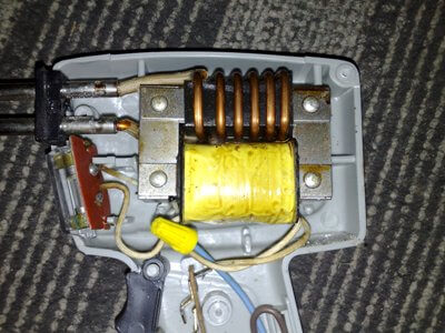
A 12 Volt winding consists of 8-10 turns of 0.8-1mm wire, we need to unwind this winding and wind a new one.
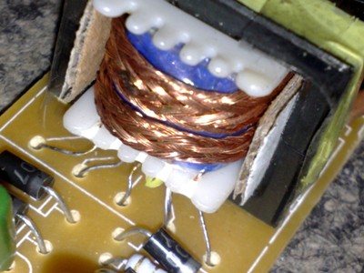
The power winding consists of only one turn; the winding is done with a busbar with a cross section of 5-6 mm. In my case, a screen from a television cable was used as a bus.
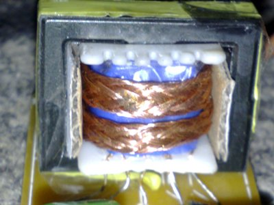
After winding, the winding needs to be given some durability. To do this, pieces of cardboard are inserted into the sides of the core.
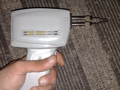
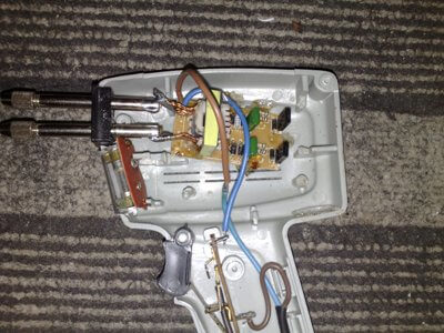
Previously, I had a German soldering iron in the form of a pistol. The basis of operation of such a soldering iron is the same as that of a pulsed soldering iron, only it uses a network transformer. Working with this soldering iron is extremely inconvenient due to its heavy weight, and when turned on for a long time, the transformer overheats very much (once the mains winding even burned out, I had to wind it myself).


In our scheme there are no such shortcomings; even without heat sinks, the heat generation on the keys is insignificant.
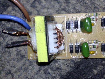
The ends of the bus are simply soldered to the tip holder, there is practically no heat generation here, which means the solder will stick.


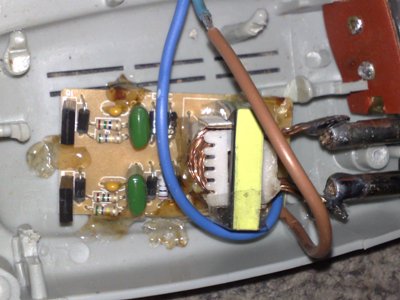
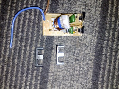
I reinforced the electronic transformer board using ordinary silicone; I did not use any additional gadgets or devices.
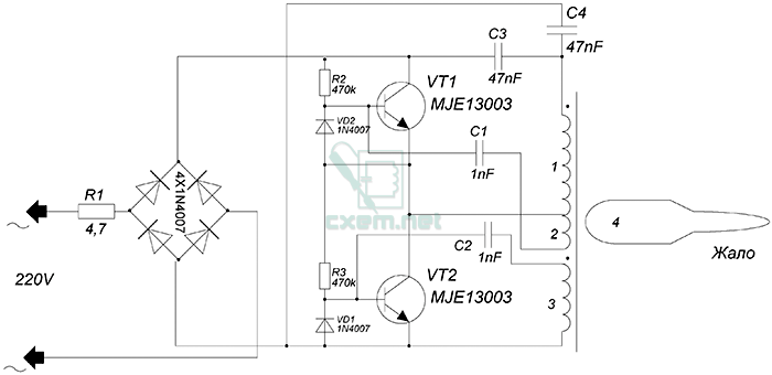
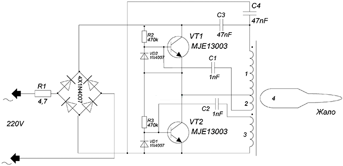
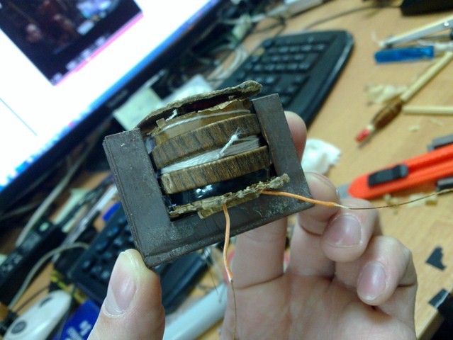
The circuit of such ETs is standard - a half-bridge inverter, unlike the circuits of the manufacturer Taschibra, this unit is quite stable, there is no separate OS transformer, and the basic windings of the switches are wound on the main transformer. See the diagram below.
During operation, the winding does not heat up, but when switched on for a long time, heat is transferred from the tip to the winding.
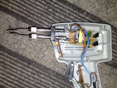
The soldering iron turned out to be quite light, the tip heats up in just 5-6 seconds. It can be used for installation work, but for larger-scale projects (tinning boards, etc.) such a soldering iron is not the best option.
List of radioelements
| Designation | Type | Denomination | Quantity | Note | Shop | My notepad |
|---|---|---|---|---|---|---|
| VT1, VT2 | Bipolar transistor | MJE13003 | 2 | Search in Chip and Dip | To notepad | |
| Rectifier diode | 1N4007 | 4 | Search in Chip and Dip | To notepad | ||
| VD1, VD2 | Rectifier diode |
DIY pulse soldering iron
Post pulse soldering iron circuit It came to mind after I came across it on one of the forums. The advantage of pulse homemade soldering iron is the rapid heating of the tip, and also the convenience of soldering small parts.
This is a soldering iron with a low-power, compact 50W electronic transformer inside. Unlike high-power ETs, the transformer is made on an W-shaped core; winding the required winding is very inconvenient, so first you need to desolder and disassemble the transformer.
Device diagram:
A 12 Volt winding consists of 8-10 turns of 0.8-1mm wire, we need to unwind this winding and wind a new one.


The power winding consists of only one turn; the winding is done with a busbar with a cross section of 5-6 mm. In my case, a screen from a television cable was used as a bus.

After winding, the winding needs to be given some durability. To do this, pieces of cardboard are inserted into the sides of the core.
Previously, I had a German soldering iron in the form of a pistol. The basis of operation of such a soldering iron is the same as that of a pulsed soldering iron, only it uses a network transformer. Working with this soldering iron is extremely inconvenient due to its heavy weight, and when turned on for a long time, the transformer overheats very much (once the mains winding even burned out, I had to wind it myself).
In our scheme there are no such shortcomings; even without heat sinks, the heat generation on the keys is insignificant.
The ends of the bus are simply soldered to the tip holder, there is practically no heat generation here, which means the solder will stick.
I reinforced the electronic transformer board using ordinary silicone; I did not use any additional gadgets or devices.
The circuit of such ETs is standard - a half-bridge inverter, unlike the circuits of the manufacturer Taschibra, this unit is quite stable, there is no separate OS transformer, and the basic windings of the switches are wound on the main transformer.
During operation, the winding does not heat up, but when switched on for a long time, heat is transferred from the tip to the winding.

Soldering iron It turned out to be quite light, the tip heats up in just 5-6 seconds. It can be used for installation work, but for larger-scale tasks (tinning boards, etc.) such a soldering iron is not the best option.
Download PCB
In general, I saw this miracle device from our engineer Gennadich... a good guy, smart. solders everything and everyone! and even had a chance to solder it to them. I tried for a long time to persuade him to collect it. but he’s not into what)
I decided I would do it myself.
I took out the transformer, it turned out it wasn’t him, Gennadich exchanged me the wrong one for that one))
and off we go.
I scoured the Internet... found 3 instructions - 300 tips.... very good good book, and 2 sources on forums - people collected similar things... but what’s strange... the book is written, so to speak, for those in the know.... unfortunately at the university they read the course on transformers somewhat fluently.... and after so many years already You won’t remember anything... on the forums they write fluently and briefly... and again, as if for those in the know... that’s actually why I’m writing this post.
I want to tell the ordinary and in simple language how to assemble this miracle device.
First, I’ll explain “why, if there are ordinary soldering irons?”
firstly, unlike the usual one, this one warms up to operating temperature in seconds and becomes cooled down in seconds, so you can put it in your bag and take it away. that's exactly what it was made for. At one time (although maybe now), these soldering irons were made by guys who repaired TVs at home. By the way, they say you can buy it...industrial, so to speak...but putting it together is more interesting + much cheaper.
By the way about costs. The soldering iron cost me 40 rubles. 20 for a button, 20 for a diode)
so what we need:
1) transformer. here, on the advice of an experienced person, I took a Soviet TVK-110-l transformer (you can find it in old TVs.) When asked why this particular one, they said that it was suitable in terms of power + in terms of dimensions. After assembly, I realized that the transformer can be anything and in the future I plan to assemble it on a different one.
2) tire. copper. thickness 2-3 mm, width 6-8 mm... (I had 2 by 6) and length about 40 cm. (the tire can be taken from power units or they say there is one in old starters too, I got it from electricians)
3) 2nd transformer with a thicker winding or a winding or copper wire. I was lucky, I found the 2nd transformer which had a thicker winding...about 0.3mm. I don’t know for sure - the guideline was simple, the thickness of the winding should be 2 times greater than the primary winding of the TVK-110-l.
4) this is a button that can withstand high current and voltage surges. those. not small buttons from a mouse
5) lamp - if desired, if necessary, it can be a 220V halogen connected directly, or, as I did, an LED (then you will need another diode in order to alternating current became permanent (roughly speaking)), or a regular 12V car lamp or small ones with a 2.5, 3.5 volt thread...as your heart desires. We can make any voltage on the lamp using the secondary winding - the more we wind it, the greater the voltage.
6) the structural part is either a handle, if you want a pistol version. or you can use a ball or another frame... and place our transformer inside it... whatever your heart desires.
7) of course a multimeter
8) soldering iron
9) electrical tape(s)
10) a hammer and pliers will not hurt.
11) screwdrivers, bolts, nuts and piece copper wire about 2-3mm thick...for the sting.
and so the assembly:
first thing We carefully disassemble the transformer and wind up the ENTIRE winding! 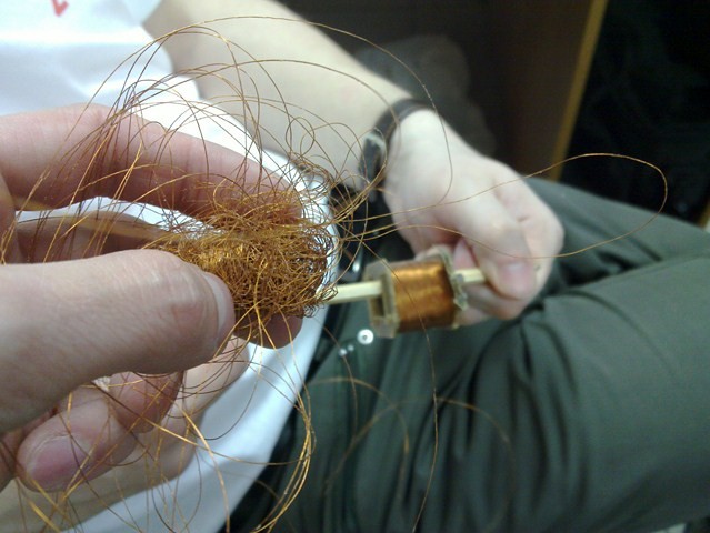
then we wind up a thicker winding from the second transformer (which is 2 times larger than the primary in the one indicated above) or, if there is one, we prepare it for winding.
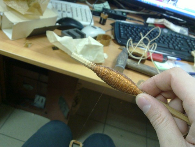
wind the winding- the thicker one instead of the primary on our original transformer 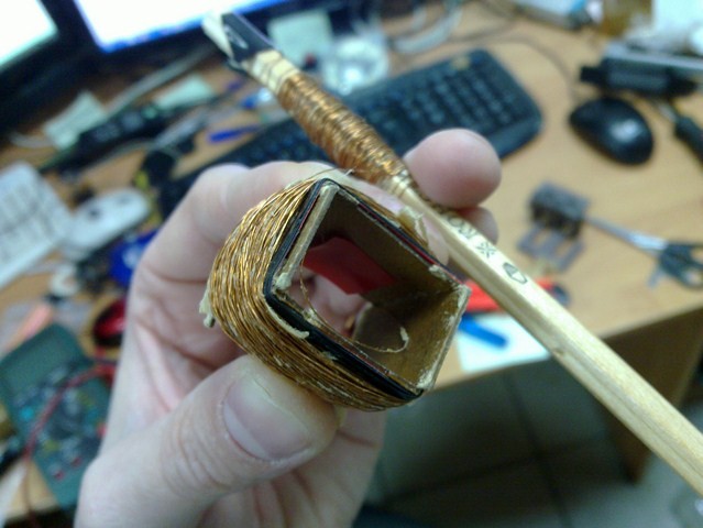
We do it as evenly and compactly as possible. because we still have to wind the tire from above and we need the W-shaped pieces of iron to fall into place - as you remember, the space there is limited.
you need to wind it so that The resistance of this winding turned out to be 40-50 Ohms(the smaller it is, the faster the sting will heat up!). will help us with this Multimeter. approximately 1500 branches as they say in books.
Advice: it’s better to wind more - it’s easier to cut than to solder and extend.)
After that how we wound the primary and got 40-50 Ohms. insulator. old - which was on the original transformer - isolate primary winding. I secured it with nylon threads for reliability.
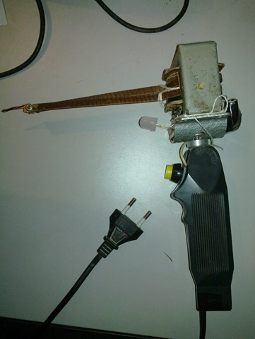
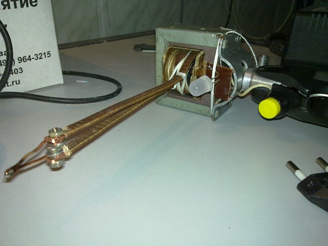
Next we wind 2.5 turns of the tire. and you won’t be able to do more, and there won’t be enough space or length. for the sting we leave about 9-10 cm. (although this is probably at will, whatever is convenient for you. I was based on Gennadich’s sample) you should get something like the following picture: 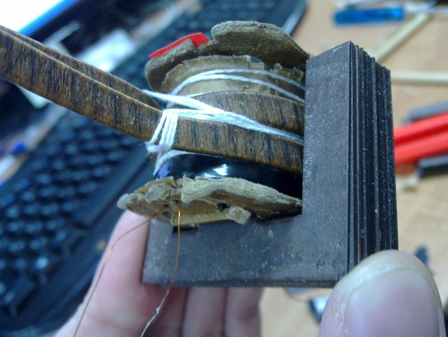
under the sting I have a 2.8 volt secondary wound under black electrical tape to power the diode. wound with a primary from the original TVK-110-L transformer. about 30-40 turns. Accordingly, if we install a car lamp, then we need to wind it more, up to 12 volts. I tied the taps for the tip together with a nylon thread... so that they fit more tightly. You can see in the photo above. + I insulated the taps of the primary winding... for reliability.
basically everything. Our soldering iron is structurally ready. you can assemble the pieces of iron, secure them, apply 220 to the primary and see whether it is heating up or not and how many volts are on the secondary under the lamp. It was in this way that the voltage to power the diode on the second secondary was selected experimentally.
You can also assemble a sting to check: 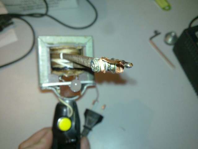
Here, too, there is enough imagination. - You can use bolts... You can also use some kind of fastenings.
Next, I would advise you to think through the design of the entire device.
I personally decided to make it with a pistol-pen so that a suitable and very comfortable pen would catch my eye. 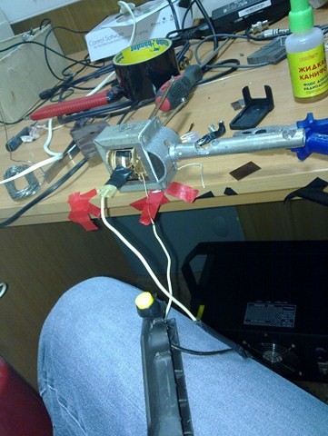
here, too, there is complete freedom of imagination: if you have a handle like this, you can use a handle, you can just use a piece of iron... you can do it even simpler... 2 pieces of wood in a T-shape are fastened to each other... cut inside for wires... (this is exactly the option Gennadich had) but I took a more difficult route because I liked the pen and found suitable material for fastening.
Yes. Important Note
when you assemble the transformer, the plates should fit very tightly to each other - although you will already understand this - when you turn it on and the plates are not secured well, they will vibrate and hum. It may be necessary to drive in additional plates. I also advise you to drive in dielectric plates on the sides of the bus -on the picture if you look closely you can see them.
Well, we’re thinking about the wiring, installing the lamp, buttons and external aspects.
and one more note!
When driving in additional plates, be careful not to break the primary winding. Unfortunately, I did this and had to disassemble everything and rewind the primary. fortunately there was a supply.
OK it's all over Now. Agree, nothing complicated?
The main thing is not to rush and do everything consciously and carefully.
in the end it will turn out something like 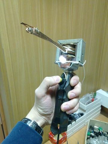
In the future, everything will be painted and hidden to make it aesthetically better.
and don’t be alarmed, at first the transformer will get very hot - it will always do this during long-term soldering and at first it will stink and smoke until everything burns out there.
good luck with the assembly everyone.
I'm glad if I helped anyone.
If you have any questions, write and I will answer.
whoever collects it, share it and show it.
+ share ideas for modifications.
If I manage to assemble it on another transformer, I’ll definitely comment.
Today, the variety of soldering irons and soldering stations is so great that it is often difficult to choose the most suitable one for a certain type of work without consulting specialists. The main difficulty in choosing arises when you need to know about technical specifications, operating behavior, reliability and practicality in servicing the soldering iron. Nowadays, for this, it is convenient to use various Internet forums where you can read and take part in discussions on topics that interest you. The World Wide Web makes it possible to hear (or rather read) opinions large quantity people in the shortest possible time, and accordingly quickly make a purchasing decision
one device or another.
Our blog already contains materials about thermal air and infrared soldering stations, as well as soldering complexes for lead-free soldering. Let's diversify this list with a lesser-known type of soldering iron - pulse. At the same time, let's get to know him. A pulse soldering iron will represent this type of tool. STING, Ukrainian production.
The pulse soldering iron is designed for mounting or dismantling elements and assemblies of electronic and electrical products. A copper wire tip is used as a heating element. Heating of the tip occurs as a result of passing a low voltage electric current through it. A pulse soldering iron consumes extremely little electricity, since current is passed through the tip only during soldering.
Ergonomics and design features of the STING pulse soldering iron
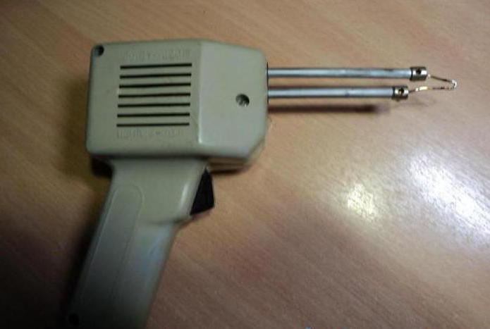
How many of you have seen a soldering iron of this shape? When I first met him, I was, to tell the truth, surprised by his appearance. Agree, most of us are accustomed to soldering irons with a straight handle and tip.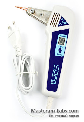
Here, as you can see, the body is made in the shape of the letter “L” and is shaped like a pistol. This made it possible to place all the circuit elements and working units in the soldering iron handle itself, while maintaining the ability to conveniently work with it.
The control of the STING pulse soldering iron is simple, and most importantly convenient. Only two buttons are responsible for this: selecting the power level and heating the tip. The latter must be constantly held during operation, during which time heating will occur. After releasing it, the sting cools down. The power level is selected using the "Select" button. The setting occurs from smaller to larger values and vice versa.
This is, perhaps, all that concerns management. True, there is also a mode of forced heating of the tip, but more on that later.
Technical characteristics of the STING pulse soldering iron
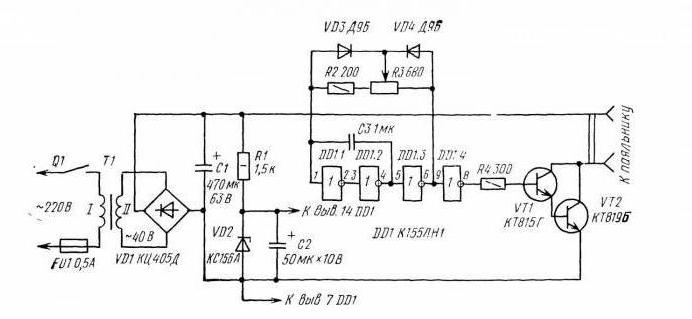
STING pulse soldering iron device
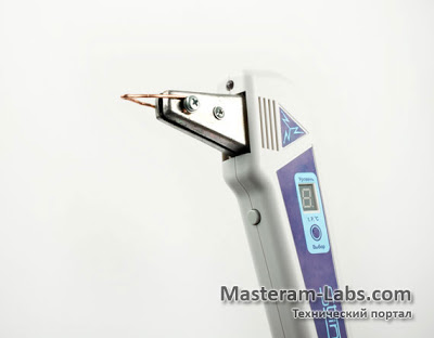
The STING pulse soldering iron consists of: a mains voltage converter into high-frequency voltage (18 - 40 KHz), a high-frequency step-down transformer and a microprocessor control system. The secondary winding of the transformer (volume coil) consists of current collectors, to which the sting is attached with screws. The built-in stabilization system ensures the desired level of soldering iron power, regardless of the network voltage (within 145 - 270 V). The power level indicator informs you about the selected temperature range, and LED lights illuminates the soldering area. The soldering iron is housed in a body made of heat-resistant, impact-resistant plastic.
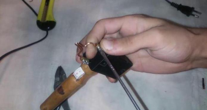
The copper tip is attached to the brushes using a bolt and nut. Since the tips will be changed frequently, this solution will allow them to be changed without damaging the brushes, which are made of copper. The threads directly in them would wear out due to the softness of the metal.
The soldering iron is equipped with an LED to illuminate the soldering area.
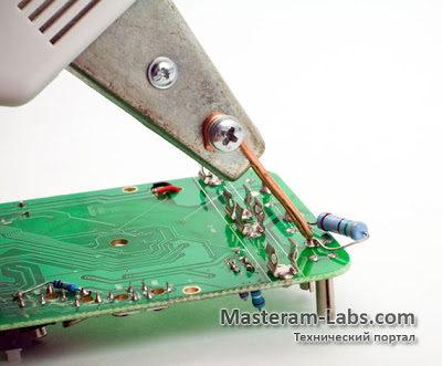
Pulse soldering iron STING in use
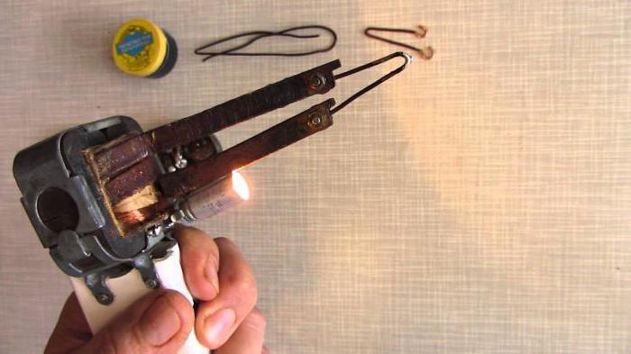
When I first came across a pulse soldering iron, I was very interested in trying out how it soldered. I was immediately amazed by the speed of heating of the tip. Just a few seconds and you can get to work. This is possible due to the fact that current passes through the body of the tip ( copper wire), and instantly warms it up. When soldering, the tip constantly maintains a stable temperature thanks to microprocessor control.Despite the specific shape of the pulse soldering iron, it is convenient to use, although at first it is unusual to hold down the heat button all the time. The STING soldering iron is designed for repeated short-term operation. The brushes to which the tip is attached and the body near them get quite hot, so the soldering iron needs to be given some time to cool down. Be careful not to touch this part of the housing during operation! After 20 seconds of holding the heating button, the control system itself turns off the power to the tip; to resume heating, you need to release and press the button again. This operating algorithm prevents emergency mode when for some reason the heating button gets jammed or is pressed accidentally, which can lead to overheating of the soldering iron.
The STING pulse soldering iron uses copper wire as a tip, selected in accordance with maximum power. For smaller wire cross-sections there are restrictions on the maximum current flow. We create a table of approximate correspondence between the wire diameter and the permissible power level:
| Wire diameter, mm. | Power level | Forced heating time, sec. |
| 1,2 | 1..2 | 0...1 |
| 1,5 | 3..5 | 2...4 |
| 1,8 | 6..10 (F) | 5 |
Recommended length copper conductor for the tip - 120 mm. Work area The tips should be cleaned to a shine, completely removing the insulating coating.
The soldering iron goes into standby mode if it is not used for more than 3 minutes.
A few words about forcing the heating of the tip. To set the forced heating time, you need to press the two control buttons together for a few seconds, then release, and when the indication on the display flashes, use the "Select" button to set required value(from 0 to 5 sec).
Considering that it is more convenient to select the soldering mode by temperature level, I conducted a small test and measured the temperature of the tip at each power level. Here is the data received:
| Power level | Tip temperature, ºC |
| 1 | 110 |
| 2 | 150 |
| 3 | 200 |
| 4 | 275 |
| 5 | 350 |
| 6 | 390 |
| 7 | 430 |
| 8 | 490 |
| 9 | 550 |
| F | 580 |
Impressions from the operation of the STING pulse soldering iron
The heating speed of the soldering iron tip is very impressive. After all, here a heating element and the sting is the same. Just a few seconds and the soldering iron is ready for use. True, copper wire wears out much faster than a metal nozzle.The supplied wire for the tips has a cross-section of 2.5 square meters. mm, and is capable of passing current up to 20 A. Using more thin wire, follow the recommendations for selecting the power level for a specific diameter.
The soldering iron is convenient to use. Considering the ease of maintenance of such a tool, as well as practicality in operation, I recommend the STING pulse soldering iron for quick soldering of electronic components. It will save you time and energy consumption.
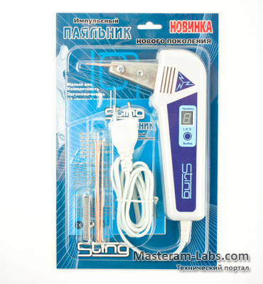
Complete set of pulse soldering iron STING
The STING pulse soldering iron is packaged in a blister. The package consists of the following items:- Soldering iron
- Copper wires for stings
- Solder
- Instructions
14 comments:
Anonymous comments...
The shape of the sting turns out to be awkward - it's just a bent wire. And a button that must be constantly pressed every 20 seconds. As far as I understand, there is no feedback on temperature. In general, besides quick warming up (and this is far from the main thing), there are only disadvantages.
Anonymous comments...
Yes, indeed, the shape of the tip does not allow this soldering iron to be used for fine work. It is more suitable for soldering large leads of radio elements or thick wires.
There are quite a few advantages in STING: ease of maintenance of the tips (also cheap), fast heating, saving energy consumption. In general, the soldering iron is really specific.
And as for the button: pressed - soldered!
Regsin comments...
I’ve been soldering with a similar soldering iron (only an even larger one with a low-frequency transformer without power adjustment) for about twenty years, and no matter how hard I tried to switch to regular ones, they always left an unpleasant aftertaste. It’s just somehow unnatural to wait half a minute...a minute to solder something in 2...3 seconds, and also make sure that they don’t touch anything, plus always have three...four types of soldering irons available For different cases, and if, as normal, you still hang around with separate block thermal stabilization and a set of stings.
Soldering irons of this kind are simply irreplaceable when repairing equipment, especially on the road. (and the advantage of this type of soldering iron is not much in the speed of heating, but in the absence of the need for a workplace - after all, the soldering iron also instantly cools down and you can put it anywhere, without fear of people ruining the furniture or scorching the body of the TV when the hostess circling around you still catches per wire.)
Regarding the shape of the tip, there is a special point here: it is indeed very specific and you need to get used to it, but having gotten used to soldering, it’s just a pleasure - I even manage to use it to bend the bent terminals of the elements during soldering and easily unsolder three-terminal SMD transistors without damaging them. But when I picked up a similar soldering iron only with a vertical loop, I almost threw it into the wall :). So the main thing here is habit.
And most importantly regarding tip temperature and power. The trick is this: the more power, the better soldering iron warms up massive leads and components, but if the heat is not removed (by simply pressing a button and not soldering or trying to solder) small parts) the tip quickly heats up to a high temperature of 500...600 degrees and can cause damage to components and tracks. And simply limiting the power will not help here since the tip is thin and not energy-intensive (it cools down immediately). Here you cannot do without feedback on the temperature of the tip (which is difficult to implement in this design). But pulse soldering irons have a unique ability to intuitively achieve an acceptable temperature by turning the power button on and off. It sounds absurd, but over many years I have become so accustomed to this type of soldering that I can even solder massive
transformer output and many SMD components(without damaging them) and resolder components many times on terrible Soviet getenax boards without fear of peeling off the tracks (which when using regular soldering iron It does not always work). It’s like learning how to ride a bicycle – once you learn it, you don’t think about it, everything happens intuitively. IN general outline The nature of soldering is this: first you press the button and warm it up, when you see that the solder begins to melt, you release the button and after a while, periodically pressing it, you maintain the temperature without allowing the solder to cool. This is, of course, a rough description, but based on extensive experience, you can approximately determine the time intervals of the pressed and released state of the button for most soldered components (large and small) and then not think about it - you get a kind of “intuitive” Feedback"
A very good option is lighting, but if there was also a smoke removal system, it would not be worth the price.
Anonymous comments...
I completely agree with regsin:+ I would like to add for those who have crooked hands: you will first learn how to solder correctly with such a soldering iron, and only then will you say about it that it is not convenient...
I also use a similar soldering iron (only with a low-frequency (50Hz) transformer from.... 1980 to this day!
You just need to be able to control it: press it for a couple of seconds, take the tip of the tip much tin and turn it off. While the tip is hot (a few more seconds), dip it in rosin (if we solder with rosin) and... calmly bring it to the place where soldering is required - turn it on and wait until everything warms up and spreads evenly and... turn it off!
The soldering turns out just brilliant!
There is no need to keep the soldering iron on for a long time: the tip overheats, the tin simply “dries out” and soldering fails.
What kind of temperature feedback is there? (nonsense...) See for yourself the state of the solder.
You have no idea; I have re-soldered so much equipment! And indeed; - it is more suitable for soldering large leads and wires (but this is the main part of the equipment). But with such a soldering iron, in some cases (and almost always) I repair cell phones. It’s just necessary.. ... modify the soldering iron tip. If anyone is interested: write to [email protected] I will send both photos and videos of how to “steer” such a device. Otherwise, it might turn out like in that Krylov fable about the monkey and glasses....
With respect to all soldering workers: Angeli Vladimir Panteleevich RW9WR (ex:OK8ACW) radio amateur since 1965....
Anonymous comments...
Pulse soldering irons are generally a specific matter, you need to get used to them, so having gotten used to low-frequency soldering irons, you want something the same but lighter, yet their main drawback is still their weight. So about the Sting, the weight is much less, and there is the ability to adjust the power, and forced preheating, these are advantages, it is also one of a kind, it can only be compared with its low-frequency counterparts.
So, our designers didn’t even bother to look at these brothers, they only looked at the Soviet “Iskra”, or maybe even the “Moment”, from which they borrowed the shape of the tip and its fasteners, and the fact that the imported analogues have long been no longer wire in the form of a tip, and the tip is in the form of a loop, it differs from the wire, in shape, different cross-section, the designers of this revolutionary device do not need to know, but the main revolutionary solution is the current-carrying bars, they are very revolutionary for this type of soldering iron, made of STAMPED STEEL SHEET, it is from this that not made of copper, as a result, when working, which is natural, the busbars heat up almost as well as the tip, but they cool down like an ordinary nichrome soldering iron, the tip is already cold, but you can’t touch the busbar yet, that’s why the thickness of the tip, excuse the wires, is only 1.5 mm, which in the first place is inconvenient, in the second case it is short-lived, but with a larger thickness I’m afraid I’ll have to solder with a busbar, and not with a wire in the form of a tip.
I dare to note all this at a not at all low price, so kudos to the manufacturers, this is truly a revolutionary device.
Anonymous comments...
Two of these soldering irons have passed through my hands - the first one exploded after a week - they were replaced under warranty without any questions. The second one, after a month of operation, stopped turning on (the sign A blinks with obvious flickering on the indicator and there is no reaction to any button) after all sorts of perversions, I taught it to turn on by holding two buttons at the same time when turning on the power plug. The cheeks in it really resemble steel, but in fact it’s copper, it’s really very thin for some reason, and it’s also chrome-plated, and after half an hour of work, this chrome becomes dirty black from the temperature of the cheeks themselves, the plastic near them begins to float and the stickers in this place are on both sides bubbles, although heating is also facilitated by the massive brass bushing located inside the HF trance and being part of the power coil, although the designer of this miracle answered my question that eddy currents do not arise in a non-magnetic conductor. I had to modify everything myself - copper plates without sides 1 mm thick were inserted into the inside of each cheek over the entire area, a brass bushing was made from the same plate between the turns of thin fiberglass, an M4 thread was cut in the center (cut against the tail curved inside). For illumination, an LED was added at the bottom of the tip, which I pulled out from the body to the maximum - which prevents the index finger from slipping towards the cheeks. As a result, the heating of the cheeks decreased noticeably, and the heating of the sting improved somewhat, although the weight increased slightly. Before all these procedures, I cleaned my cheeks with fine sandpaper almost down to copper, which now do not darken.
Dima Tararoev
In our article we will talk about what a pulse soldering iron is. This tool is often used to install or dismantle elements of electronic and electrical products. A pulse soldering iron can be purchased at a store, but you can also make it yourself.
How does it work
It will be useful for those who use this tool to know how it works. Inside, the pulse soldering iron has a heating element made of copper wire. Low-frequency electrical radiation passes through it, due to which heating occurs. This soldering iron is called pulse because electricity is supplied to the heater in pulses, that is, periodically. Therefore, heating occurs only during soldering. Little energy is wasted, which means that using this tool helps save energy. It consumes only 75W and can run continuously for 15-20 minutes. In addition, the pulse soldering iron is compact and lightweight. However, he was not always like this. The design transformation was achieved thanks to modern materials and technologies. The advantages of a pulse soldering iron include the ability to solder both small and massive parts.
 You can do it yourself
The design of this tool is simple. Therefore, it will not be difficult for craftsmen to assemble a pulse soldering iron with their own hands. Inside it there is a step-down transformer, which is its main part. In order to independently assemble the tool, the master must have before his eyes a diagram of a pulse soldering iron and the necessary parts. Among them are a resistor, a housing, LEDs, and electronic protection devices. If this is your first time assembling a homemade pulse soldering iron, you need to know that the device should not overheat. Therefore, when assembling it they use special device with adjustable voltage. And heating of the tip itself is provided by a resistor with a power of 0.5 W. Such a resistor is made independently.
The Edge of Mastery
If you have a pulse soldering iron circuit, it’s not difficult to make it yourself. This tool is turned on and off using a button located on its body. For the convenience of working with a soldering iron, a low-power light bulb is mounted in it. Its tip is made of copper wire, the thickness of which will be 1 mm. The time it takes for the tool to warm up and the temperature of the tip will depend on the cross-section. The transformer core must be assembled from iron (W-shaped). For example, Sh-26, Sh-20. Next, the primary winding is made with SED wire 0.22-0.25 in the amount of 1500 turns. The same wire is used to wind the light bulb (25 turns). And then power winding The core is made of copper wire, making 5-6 turns. The copper wire must have a cross-section of 25x0.3 mm. The core is tightened from above with studs and nuts. They must be insulated with fiberglass and textolite washers. Conductive busbars are similarly insulated.
Manufacturing process
A pulse soldering iron does not have to be assembled from new parts. It can be assembled based on a transformer from old electrical equipment or even energy saving lamp. The used transformer must first be removed from the old winding, being careful not to damage the wire of the primary winding, which can also be used in the future. The size of the coil can be adjusted to accommodate both the first and second windings. In order to wind the primary winding, you can use a special machine, but some do it by hand. After completed secondary winding Copper wire can be used to insulate it.
Additional details
It is necessary to attach a handle, for example, a wooden one, to the assembled transformer, the main thing is that the material from which it is made is a dielectric. We must not forget about the button with which the soldering iron will turn on and off. Moreover, heating should occur only when the button is pressed. This is very convenient, as it saves energy and prevents the soldering iron from overheating. A copper wire tip is also made and attached. It is best if its diameter is 1-3 mm.
Making the tip
Copper wire is attached to the soldering iron using bolts or collet joints. It is necessary to decide how thick the tip is needed depending on the size of the part that will need to be soldered. Don't forget that the thinner the wire, the faster it will heat up. On the one hand, this is good, as it will allow you to get the job done quickly, but on the other hand, heat will lead to rapid burnout of the wire. The most suitable heating time is 4-8 seconds. In this case, the tip wears less. But this effect can be achieved only by increasing the cross-section of the wire. But this method also has disadvantages. An increase in cross-section leads to the fact that the soldering iron begins to consume more electricity, which means it can overheat or even ignite. To avoid undesirable consequences, you need to try the soldering iron in action, and then eliminate the shortcomings, if any.
Under your hand
You should definitely try to make a pulse soldering iron with your own hands. Such a tool is always necessary on the farm, but store-bought ones can be expensive or do not meet the declared quality. At home, a master can create a reliable soldering iron that meets all his needs. The main thing is not to make a mistake in the assembly. But everything comes with experience. A correctly assembled tool will help avoid problems with flying contacts and will be convenient and easy to use.
 (1 ratings, on average: 5,00 out of 5)