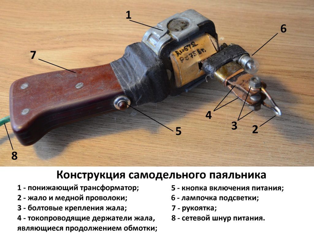
Soldering iron from an electronic transformer. Do-it-yourself electric soldering iron “Moment” from improvised means
A standard soldering iron has a heating device that consists of nichrome wire. The heat from this wire is released to the copper tip. It's easy even at home. Its only disadvantage is that you have to wait a long time until it warms up to desired temperature. But in a pulse soldering iron there is no such drawback. It received this name because its tip heats up in about 5 seconds or even faster. Most often, the soldering iron tip is made from a piece of curved copper, which has a diameter of 1 or 2 millimeters.
The pulse soldering iron tip heats up in just 5 seconds.
Pulse soldering iron and how to make it yourself
The scheme according to which it is arranged is much more complicated than usual. To make such a soldering iron with your own hands, you need an electronic type transformer. Several halogen lamps are connected to it, which have an output voltage of 12 volts. Then this transformer needs some work. Its essence is that it requires removal of the secondary winding and additional winding in the form of 1-2 turns of copper wire 1 millimeter thick. The finished, already modified winding is placed under the housing, which looks like a pistol with a trigger. This trigger will turn on the soldering device. Another change is that in the place where the barrel of the resulting pistol is located, a dielectric-type stand is placed, with a copper bracket attached to it, which is called the “sting.” Such a bracket is similar to medical tweezers, with voltage supplied to its edges through a switch with a button. To modify the resulting tool, an LED light bulb is connected to it.
![]()
With the help of a lamp it will be much easier to solder. While using such a tool, you need to be careful about one thing. You should not keep the tip in the “on” position for too long, in which heating occurs. This will help avoid damage to its electrical circuit.
Components of a pulse soldering iron:
- electronic type transformer;
- halogen bulbs;
- copper tip;
- LEDs.
Return to contents
Self-production of a microcircuit soldering iron
The difference between microcircuit soldering irons and devices of other types is that there is absolutely no tolerance for overheating of its electronic component.
The only thing required is presence special devices for protection that protect microcircuits from damage. In such soldering irons, the device that acts as a power supply unit is best used as follows. It must have an adjustable output voltage ranging from 0 to 15 volts. The element that will cause heating can be an MLT resistor with a nominal value of about 8 Ohms and a power of 0.5 Watts; sometimes ultrasound is used for this.
To make such a resistor, you need to remove one leg and make a hole (using drilling) in the place where it is attached, having a thickness of 1.1 millimeters. To maintain safety, you need to use a piece of mica to protect its end from touching the internal cavity of the resistor bowl when the tip is inserted. This creates a soldering iron for microcircuits. It is best to attach an already “modified” soldering iron to the end of its body with any broken handle in which the rod has run out. This is done using a special textolite having two sides, or a mounting plate. Thanks to this, the resistor-type heater receives voltage from the power supply unit. The tool is ready.
Components of a microcircuit analogue:
- resistor (power supply);
- means for protection against breakage;
- ballpoint pen body;
- LEDs.
Thus, taking into account all of the above, you can make a soldering iron with your own hands at home, both pulsed and for microcircuits.
It is known that for soldering wires, radio components or various metal structures You need to briefly heat the solder to melt it, and warm up the soldered surfaces of the conductors to the required temperature.
With repeated soldering, the process of preparing parts for installation takes much more time than briefly touching a heated tip to the surfaces being soldered.
Obviously, in this case, a regular (factory or homemade) soldering iron most idle time uselessly, dissipating consumed energy. To reduce the unnecessary power consumption of soldering tools when they are idle, a pulse soldering iron was developed,
Industrial pulse soldering iron
switched on briefly only during soldering. Name this tool received due to the consumption of electricity in the form of short-term pulses, period of several seconds, sufficient to warm up the tip and perform the work.
Operating principle
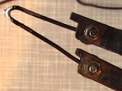
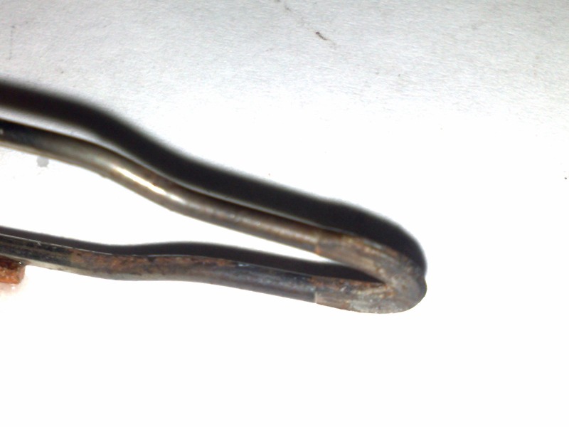
The main difference between a pulse soldering iron is the method of heating its tip, which is bent in an arc copper wire (like the letter "U"), through which electricity great strength required to achieve the required temperature.

Heating copper wire in the form of a sting
The power supply of such a soldering iron must provide an output voltage of 1-2 V and a current of 25-50 A. Until recently, a conventional transformer was actively used for these purposes, in which the secondary winding is made in the form of several turns of a copper bus relative to large section(several times larger than the cross-section of the tip wire, in order to avoid heating the winding itself during operation).
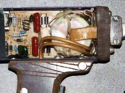
Also, the conductive bars that serve as a tip holder must have a large cross-section, so they are placed in the body of a pulse soldering iron, which, due to the revolving handle, resembles a pistol.

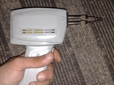
Typical shape of an industrial pulse soldering iron
But the considerable dimensions and noticeable weight of the step-down transformer make working with a soldering iron inconvenient, so in Lately switching power supplies, which are much smaller and lighter, began to be used.
Current sources used to power pulsed soldering irons
Pulse soldering irons also have this name because of the improvement and miniaturization of power supplies used in these tools that use electronic circuit converting high-frequency voltage pulses, although regular a step-down transformer suitable power.
Therefore, when creating a pulse soldering iron with your own hands, you need to decide which power supply will be used - with a step-down transformer, or electronic. The advantage of the first option is that it is extremely simple electrical diagram– the terminals of the secondary winding are directly connected to the conductive busbars.
An example of a homemade soldering iron with a step-down transformer
Disadvantages include the dimensions and weight of the device, as well as noticeable vibration during operation. In addition, the primary winding very often burns out due to unstable voltage and frequent overloads, and it is impossible to independently rewind it without special equipment and the appropriate winding wire.
Therefore, many radio amateurs, when repairing a failed pulse soldering iron based on a step-down transformer, use suitable the electronic unit nutrition, replacing the secondary winding.
Burnt-out step-down transformer in an industrial soldering iron
The bulky transformer is replaced with a miniature electronic board
The process of converting a step-down transformer
When making a pulse soldering iron, you can use an existing step-down transformer to power it, which can be with any type of magnetic circuit, the main thing is that it is suitable for power in the range of 50-150 W.
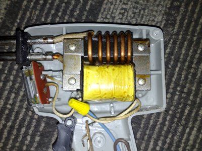
The primary network winding is left unchanged, and the secondary is removed by disassembling the transformer. Since current is decisive for heating the soldering iron tip, then by exact calculation the number of turns can be neglected, concentrating efforts on achieving the maximum possible cross-sectional area of the winding busbar.
As a rule, two turns of copper bus bar or braided flexible wire will be sufficient. copper wire, with a cross section of 6-10 mm², which must be positioned in such a way that they do not short circuit with each other and the transformer core.
Copper busbar in the form of a secondary winding
In the case of using a copper bus as a winding, its terminals will serve as a tip holder.

The continuation of the winding is the tip holder
The elastic bus should be wound carefully so as not to damage the primary winding, after which it should be checked for breaks and short circuits.
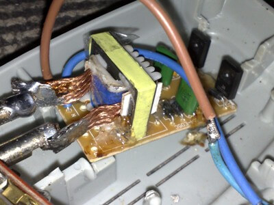
Remaking an electronic transformer
Creating a pulse soldering iron with their own hands from scratch, or using a ready-made case with holders, many radio amateurs use the existing electronic power supply for 12V halogen lamps with a power of 50-150W as a transformer, while also remaking the secondary winding.
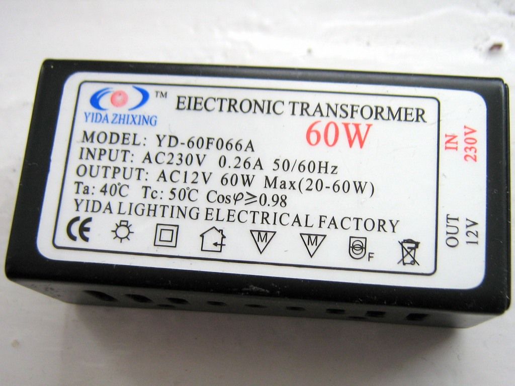
Electronic transformer (switching power supply for halogen lamps)
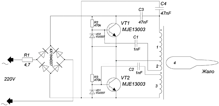
Since no other changes to the device are required, a typical electrical circuit diagram The switching power supply is given only as an example, without analyzing the functions of the elements and describing the operating principle.
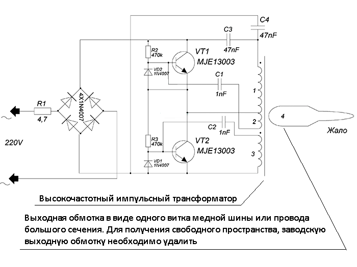
Pulse transformer in the diagram, subject to alteration
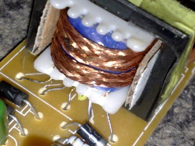
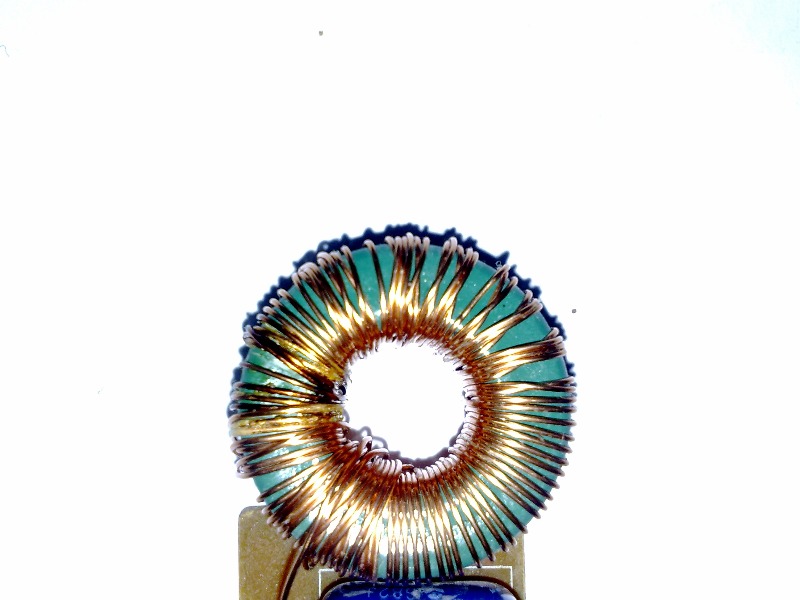
In this case, you need to remember that to achieve the required voltage in a pulse transformer, smaller magnetic core dimensions and fewer turns are required, so one turn may be enough to remake the secondary winding.
One output turn on the toroidal magnetic core of the pulse transformer
If your existing tire or flexible wire the cross-section is insufficient, it can be increased by parallel connection turns of windings.

Connecting the leads of parallel turns to the tip holder

Parallel turns of flexible braided copper stranded wire
Since the old secondary winding can be removed without disassembling the transformer, and a new one can be created simply by inserting one turn into the voids between the insulation and the magnetic circuit, the process of remaking a switching power supply is not too difficult even for a novice craftsman.
Making a soldering iron tip
As a soldering iron tip, you need to use copper wire with a diameter of 1-2 mm, connecting it to the holders using bolted or ready-made collet connections.
Bolt fastenings of the sting on the plates
More accurately, the thickness of the wire is determined experimentally - by the speed with which the temperature of the soldering iron reaches the operating range - the thinner the tip wire, the faster it will heat up. But on the other hand, too high a temperature will make the soldering process impossible and will lead to rapid wear and even burnout of the wire.
By increasing the cross-section of the wire, it is necessary to achieve an acceptable time (4-8 seconds) for heating the tip and preventing it from overheating. It must be remembered that with an increase in the cross-sectional area of the tip wire, the power consumption and heating of the secondary winding of the transformer increase.
Therefore, having selected the desired diameter of the tip wire and tested homemade soldering iron in operation, after carrying out the soldering process several times, you need to check the heating of the secondary winding - it should not heat up too much, much less get hot - otherwise the transformer may overheat, which will lead to burnout of the primary winding and ignition of the insulation.
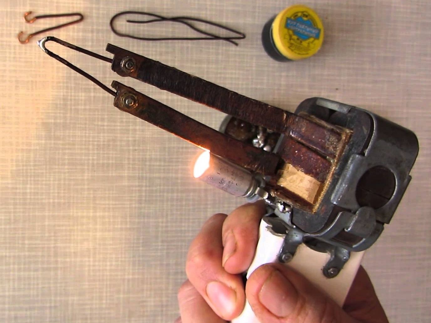
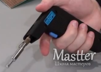
For ease of operation, a light bulb or LED is often connected, which turns on synchronously and illuminates the soldering area.
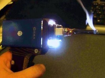
A bright LED turns on synchronously with the soldering iron, illuminating the soldering area
Advantages and disadvantages
Having picked up the necessary parts on the market, or disassembled other devices, having minimal skills in radio engineering, you can assemble such a soldering iron with your own hands, adding to your arsenal a tool that will compare favorably in the following parameters:
- Economical – no electricity is used when the tool is idle;
- Safety - the tip is always inoperative cold, which eliminates skin burns, fires of objects and melting of the power cord insulation due to accidental touch;
- Ease of repair - no heating element eliminates its burnout, and making and replacing the tip is much simpler than that of a conventional soldering iron, where it often gets stuck.
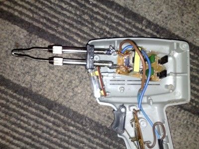
The disadvantages include its considerable size and significant weight, which requires some physical effort and causes hand fatigue after prolonged work. Therefore, many radio amateurs share the electronic circuit and pulse transformer, making the tool lighter.

Electronic circuit and pulse transformer are separated

Transformer separated from the circuit
DIY pulse soldering iron
Post pulse soldering iron circuit It came to mind after I came across it on one of the forums. The advantage of pulse homemade soldering iron is the rapid heating of the tip, and also the convenience of soldering small parts.
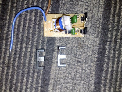
This is a soldering iron with a low-power, compact 50W electronic transformer inside. Unlike high-power ETs, the transformer is made on an W-shaped core; winding the required winding is very inconvenient, so first you need to unsolder and disassemble the transformer.
Device diagram:
A 12 Volt winding consists of 8-10 turns of 0.8-1mm wire, we need to unwind this winding and wind a new one.
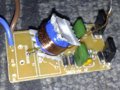
The power winding consists of only one turn; the winding is done with a busbar with a cross section of 5-6 mm. In my case, a screen from a television cable was used as a bus.
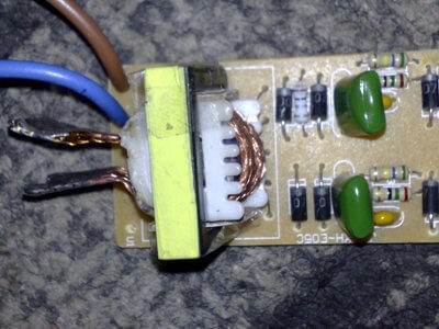
After winding, the winding needs to be given some durability. To do this, pieces of cardboard are inserted into the sides of the core.
Previously, I had a German soldering iron in the form of a pistol. The basis of operation of such a soldering iron is the same as that of a pulsed soldering iron, only it uses a network transformer. Working with this soldering iron is extremely inconvenient due to its heavy weight, and when turned on for a long time, the transformer overheats very much (once the mains winding even burned out, I had to wind it myself).

In our scheme there are no such shortcomings; even without heat sinks, the heat generation on the keys is insignificant.
The ends of the bus are simply soldered to the tip holder, there is practically no heat generation here, which means the solder will stick.
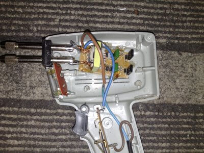
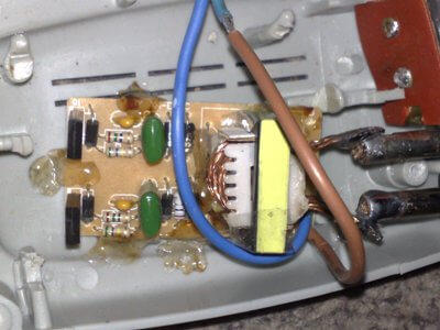
I reinforced the electronic transformer board using ordinary silicone; I did not use any additional gadgets or devices.
The circuit of such ETs is standard - a half-bridge inverter, unlike the circuits of the manufacturer Taschibra, this unit is quite stable, there is no separate OS transformer, and the basic windings of the switches are wound on the main transformer.
During operation, the winding does not heat up, but when switched on for a long time, heat is transferred from the tip to the winding.
Soldering iron turned out to be quite light, the tip heats up in just 5-6 seconds. It can be used for installation work, but for larger-scale tasks (tinning boards, etc.) such a soldering iron is not the best the best option.
Download PCB
A soldering iron is the main “weapon” of an electronics engineer. You can make a fairly powerful, compact and lightweight soldering iron with your own hands. This homemade soldering iron differs from the devices known to us in that there is no tip heater, or rather, there is one, but the operating principle is completely different. IN regular soldering irons A fairly simple and trouble-free principle of heating the tip is used - a nichrome spiral. The spiral plays a role heating element, the heat of which is transferred to the sting. We are all used to waiting for a while until the soldering iron warms up - this is sometimes very annoying if the work is urgent.
How to make a pulse soldering iron
The soldering iron we are going to make is Warms up in just 5 seconds, during this time he acquires the ability to melt tin. The basis of such a soldering iron is a switching power supply, which uses a control circuit (ballast) from a 40-watt LDS. The ballast has network filter, consisting of chokes for filtering RF interference and capacitors for filtering network LF interference. The board also has a mains fuse and a thermistor.
The operating principle of a pulse soldering iron is based on short circuit secondary winding of the transformer, as a result of which heating occurs. The soldering iron tip is also part of the secondary winding.

The secondary winding consists of a copper busbar with a diameter of 3.5 mm; in my case, two wires of 1.7 mm each were used. The winding consists of only one turn.
Tip - a copper or nickel wire with a diameter of 1.5-2 mm connected directly to secondary winding transformer.
Transformer - ferrite ring from a pulse converter (you can use rings from electronic transformer blocks). The dimensions of the ring are not critical, the main thing is to place the windings. Primary winding(network) consists of 100-120 turns of 0.5 mm wire, stretched evenly across the entire ring.
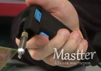
A pulse soldering iron, also known as a transformer, has an external shape that resembles a pistol. It is equipped with several removable attachments different shapes or may have a sting. It is very convenient to work with such a soldering iron. Compared to a conventional soldering iron, the advantage of a pulsed soldering iron is that its working part heats up very quickly (up to 5 seconds). Therefore, it can be turned on immediately before work. It is equipped with backlight.
Pulse soldering iron: what to look for when choosing
A soldering iron based on a pulse converter is mainly designed for repairs. household appliances and quick replacement of defective parts. The main advantage of the soldering iron is power transistors adapted for transformer loads and a converter for fluorescent lamps.
The main part of a pulse soldering iron is a step-down transformer. It heats the working part of the soldering iron, the copper arm, and the current that arises in the secondary winding is of the order of several tens of amperes. The working part of the soldering iron is made from copper wire or copper strip with a cross section of about 1 mm. Determination of the tip size is carried out in a practical way. At the same time, it must be remembered that the heating time and temperature are determined by the cross-section of the tip. For soldering you can use brazing alloys. Continuous operation time up to 20 minutes.
The best option in terms of reliability is to buy a soldering iron domestic production. When choosing, pay attention to the power of soldering irons: the lower it is, the longer the service life will be. It is worth choosing soldering irons that have a power in the range of 20 - 30 watts.
A soldering iron must be selected with a resistance of 2 kOhm. When purchasing, it is advisable to have a multimeter with you to measure the resistance of the soldering iron you like. And only after that should you make a purchase.
When choosing a soldering iron, in addition to the availability of warranty and power, you should pay attention to the availability of certificates of quality and compliance. This is additional confirmation of the quality of the product.

Pulse soldering iron Sting
The sting pulse soldering iron is designed for assembling components and elements of electrical and electronic products. The ten-level power regulator makes it possible to carry out small soldering and soldering of relatively large parts with equal ease. Thanks to the presence of forced heating, the operating temperature of the tip is reached in 1.5-2 seconds. Duration of adjustable forced heating up to 3.5 seconds. The built-in stabilizer ensures autonomy of a given power level, regardless of the supply voltage.
All modes and parameters are controlled by a microprocessor controller. The main components of the sting pulse soldering iron:
- microprocessor control system,
- high frequency step down transformer,
- mains voltage converter.
The secondary winding of the transformer is also a current collector, to which the tip is attached using screws. The power level indicator indicates the selected temperature range.
The STING soldering iron operates in intermittent mode. It is necessary to take into account that the housing near the brushes to which the tip is attached, and the brushes themselves become very hot. The soldering iron is allowed to cool for some time; you must not touch this part of the soldering iron during operation! 20 seconds after pressing the heating button, the power to the tip is automatically turned off by the control system. You need to release the button and then press it again to resume heating. This control system helps prevent the soldering iron from overheating.
 (1 ratings, on average: 5,00 out of 5)