EPR malfunctions for fluorescent lamps. DIY fluorescent lamp repair: design, diagram
Fluorescent lamps are popular due to their energy-saving component. But unlike incandescent lamps, the source circuit daylight quite complex and includes additional elements, ensuring start-up and stable operation. One such device is a ballast for fluorescent lamps.
Purpose and types of device
The main purpose of the ballast is to maintain a constant voltage at a certain level so that the glow efficiency does not decrease. Due to its purpose, this element belongs to the ballast elements gas discharge lamps daylight. In addition, if necessary, the ballast acts as a current limiter (both starting and operating).
Depending on what circuit was implemented when assembling the ballast, these starting devices are divided into two types. Let's take a closer look at them.
Electromagnetic version
The scheme by which the electromagnetic ballast works is to use a choke connected in series to the lamp bulb. A starter is also required for the starting process. This compact device has bimetallic electrodes in its body. The starter is connected in parallel with the gas-discharge lamp.
The operating principle of such a ballast is quite simple and is based on the use of inductive reactance:
- When voltage is applied to the starter electrodes, they close due to the discharge;
- This leads to a multiple increase in current, which, in turn, heats up the electrodes of the lamp itself;
- Having issued a discharge, the starter cools down and the electrodes open. This generates a sufficient impulse to cause a discharge to occur inside the flask, which will ignite the gas.
Having brought the lamp into operating mode, the electromagnetic ballast remains open, which does not interfere sustainable work lighting fixture.
Electronic variant
Electronic ballast is an ordinary input voltage converter. In this case, the scheme for launching a daylight source can be different:
- One of the methods involves preheating the cathodes of the gas-discharge bulb before applying a starting pulse to them. Thanks to this, two problems are solved: the flickering of the discharge is practically eliminated, and it also increases Lamp efficiency. This method allows you to use several launch options: instant or smooth, with a gradual increase in the brightness of the glow;
- With the combined method, circuit oscillations are used for starting. When the circuit enters resonance, a discharge occurs and the voltage increases, which ensures heating of the cathodes of the luminescent bulb.
This scheme implies that the oscillatory circuit goes out of resonance due to a change in parameters due to a discharge in the bulb of the lighting device. Consequently, the voltage drops to operating condition and the electronic ballast remains open.
Usage electronic circuit launch contributed to a significant reduction in the size of the launch structure. This led to the development and implementation of such technologies in an energy-saving compact lamp.
Advantages
The electronic “filling” of the LDS has undeniable advantages over throttle starting devices:
- Simplification of the circuit: the ballast includes all the functions of other devices;
- A more compact connection diagram, which also consumes less electricity;
- No flickering or extraneous noise during operation;
- Possibility of hot start, which extends the service life.
Checking and replacing ballast
The main problem with fluorescent lamps is their frequent breakdowns. But one of the advantages is that the repair of such light sources is quite simple: it is important to determine the true cause of the failure. Today we'll tell you how in a simple way check the ballast for functionality.
Before checking the lamp, disconnect it from the electricity.
To do this, you will need to take a regular carrier (a lamp with wires), and connect paper clips to the ends of the wires. This simple device will make it easy to short-circuit the contacts going to the lamp. Next, the following actions are performed:
- The transparent bulb is removed from the de-energized lamp. The lamp is removed from the sockets;
- We insert a curved paper clip into the cartridge in such a way as to close both contacts. Another wire coming from the carrier is connected to the second cartridge;
- After this, voltage is applied to the lamp.
If the filament lights up, it means the ballast is still “alive”. Therefore, this is not the reason, and you will have to disassemble the housing to check the remaining starting and control devices.
Replacing the electronic ballast in fluorescent lamps It is produced quite quickly: it is enough to purchase a device with the same starting characteristics. When connecting, the previous diagram must be observed. In some cases, you don’t even need to solder the wires: the connection is made using detachable contacts.
Repair features
The presence of ballast is mandatory not only for tubular structures fluorescent lamps, but also for energy-saving compact fluorescent lamps. At the same time, the design of compact gas-discharge light sources is more complex, precisely because of its small sizes. This imposes certain restrictions on the use of certain constructive solutions. In order to fit everything into a small LDS housing necessary devices, manufacturers use a simplified scheme, which leads to frequent failures of certain elements. Produce do-it-yourself repair such lighting sources are very difficult, again, due to the miniature size of all the parts.
We will look at some of the nuances involved in the repair of fluorescent lamps.
Before you begin inspecting the lamp and identifying the part that needs repair, you need to check whether voltage is supplied to the lamp. This is best checked with a tester directly at the input terminals. Most often, to get to them, you need to remove the cover and body of the lamp. If voltage is supplied, the lamp is de-energized and removed, for example, from the ceiling.
LDS repair should begin with checking the performance of the bulb. To do this, each pair of contacts is called by the tester.
Note! If you have a 4-bulb lamp body, then it is important to know what type of ballast is installed in it. If there is an electronic ballast, then if one bulb fails, all the lamps will not work. And when installing the throttle, there is only one pair.
Typical faults
The following elements most often require repair in electromagnetic devices:
- Starter. The easiest way to check its performance is to connect a 100% working starter in parallel. Here it is important to use a device that is similar in power and operating voltage;
- Throttle. If replacing the starter does not solve the problem, you will need to check the throttle winding. You can immediately replace it with a new device with the same parameters.
Repairing a lamp with an electronic start involves replacing the ballast, which we described above.
Now you know not only the structure of the main types of ballasts for fluorescent lamps, but also know how to check and repair the main elements of fluorescent lamps.
More and more compact fluorescent lamps (CFLs), commonly referred to as energy-saving lamps, are being used by the population. But, since the market is flooded with relatively cheap low-quality products, some units do not fulfill the service life declared by the manufacturer. As a result, the savings turn out to be illusory: the money spent on buying a lamp does not justify itself. Even correct operation A CFL does not guarantee that it will last long.
Faulty CFLs - many can be repaired
Sometimes a broken lamp needs to be repaired. Replacement parts can be taken from another CFL or purchased at a radio store. It will be cheaper than buying a new lamp.
Design and principle of operation of compact fluorescent lamps
To successfully repair any device, you need to know its design and operating principle. The compact fluorescent lamp consists of the parts shown in the figure.
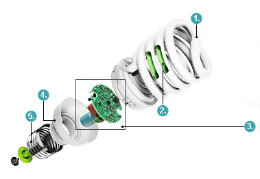
- A glass tube with mercury vapor and an inert gas inside.
- Phosphor on inner surface tubes.
- Electronic ballast.
- Frame
- Base.
Along the edges of the tube there are electrodes similar to the filaments of an incandescent lamp. At the moment of startup, a current passes through them, heating the material with which they are coated. The properties of the coating are such that when heated, free electrons begin to be emitted from it into the surrounding space.
Then the electronic ballast circuit, also called an electronic ballast (EPG), generates a high voltage pulse between the outer electrodes. A current arises in the tube due to the electrons that previously appeared during heating. As they move, they bombard the inert gas atoms in the tube, turning them into ions. The presence of positively and negatively charged particles in the tube allows current to pass through it.
As soon as a breakdown of the gas gap in the tube occurs with the formation of a sufficient number of carriers electric current, the voltage at its ends decreases.
When moving charged particles collide with mercury atoms, the latter emit light in the ultraviolet spectrum. The phosphor coating converts light into visible radiation.
Electronic ballast performs the following functions:
- ensures the passage of current through the electrodes at the moment for their heating;
- generates a pulse for breakdown of the gas gap of the flask;
- maintains the voltage on the electrodes of the flask necessary for a stable discharge in it.
The ballast circuit first converts the AC mains voltage into DC. This is necessary for the operation of the lamp's electronic circuit. Then, using a self-oscillator, an alternating voltage with a frequency of tens of thousands of hertz is generated. Due to this they decrease dimensions Electronic ballasts and ripple factor luminous flux lamps.

The rectifier consists of four diodes connected in a bridge circuit. A breaking resistor or fuse is included in the power circuit. Used as an anti-aliasing filter electrolytic capacitor paired with a throttle.
Additionally, a limiting resistor is installed in series with the rectifier circuit. Its purpose is to reduce the inrush current that occurs when power is connected while the rectifier filter capacitor is still discharged. In cheap products there is no limiting resistor and anti-aliasing filter choke.
Starting occurs due to a thermistor connected between the electrodes of the lamp. When cold, its resistance is low. After applying voltage, a current flows through it, heating both the electrodes and the thermistor itself. When heated, its resistance increases, and the current through the filament circuit decreases to a minimum value. It remains this way until the lamp is turned off and the resistor cools down. After this, the circuit is ready to start again.
Now let's look at the procedure for finding faults in CFLs and methods for eliminating them.
External inspection of a fluorescent lamp
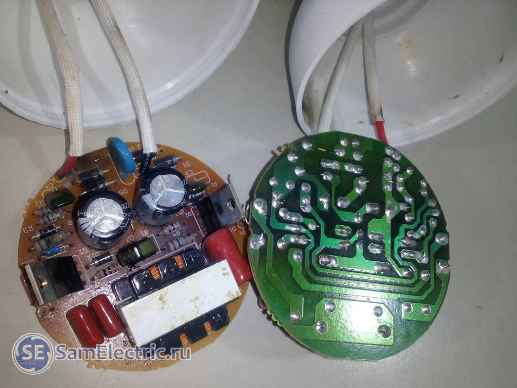
First you need to disassemble the lamp. To do this, we disconnect the halves of the housing by inserting a flat-head screwdriver into the grooves of its connecting seam. Using a screwdriver as a lever and moving it along the seam, we achieve the opening of the latches that fasten the halves together.

Then we inspect printed circuit board and parts installed on it. We check the quality of soldering - the pins of the parts should not move in the board when rocked. We inspect the tracks for integrity, check the reliability of soldering of wires to the contacts of the bulb.
There should be no traces of soot from short circuits on the parts and the board, and a swollen electrolytic capacitor requires replacement.
Filament diagnostics
A possible break in the filaments is indicated by darkening of the inner surface of the bulb at their locations. For diagnostics, the resistance of the threads is measured with a multimeter - it is about 10 ohms. If one of the threads is broken, the lamp can be made to work by soldering the threads parallel to the contacts 10 ohm resistor.
The start of a CFL with such a resistor is possible due to the electrons released near a working electrode. However it will start worse, since at this stage there will be fewer carriers, and their movement will be effective only for a certain direction of the current feeding the tube.
You can immediately check the thermistor in the filament circuit. Its resistance in a cold state must correspond to that indicated on the case.
If both threads are broken, the lamp will have to be disposed of. But electronic components You shouldn’t throw them away; they will still be useful for repairing other lamps.
Rectifier faults
Diagnostics of the electronic circuit of the lamp begins with an integrity check fuse(break resistor). Finding it is not difficult - it is connected in series to one of the base wires and is located not far from the rectifier diodes. The fuse does not blow on its own, its break is a consequence of a short circuit in the protected circuit.
A limiting resistor is also located in the same area. Its resistance is low - a few units of ohms. But sometimes manufacturers install a jumper on the board instead.
Diodes rectifiers are checked with a multimeter in turn, for which one of the terminals of each of them is unsoldered from the board. To check, set the multimeter to resistance measurement mode and touch it with the diode probes, changing the polarity of their connection. In one direction, the diode conducts current, and its resistance is equal to hundreds of Ohms, and in the other - infinity. If this is not the case or the diode has some resistance in the opposite direction, then it is replaced.
Electrolytic capacitor The power filter is checked with a multimeter: the probes are connected to the terminals in accordance with the polarity indicated on the case. At short circuit between the terminals, the absence of charging current or the unwillingness of it to decrease indefinitely, the capacitor is changed. However, a guaranteed way to ensure its serviceability is to unsolder it and temporarily replace it with a new one. The operating voltage of the capacitor is 400 V, the supply voltage of the multimeter is not enough to objectively check it.
If there is a power filter in the circuit throttle it also needs to be checked for integrity.
Troubleshooting the generator circuit
Priority search direction – semiconductor elements. In the CFL pulse generator circuit, these are transistors, diodes and a dinistor.
Dinistor is a semiconductor device that has high resistance in both directions until the voltage at its terminals exceeds a threshold value.
You can check the serviceability of the dinistor at home by replacing it with the same one or an analogue that has the same opening voltage. Indirectly, the malfunction of an element is determined by a multimeter if the measured resistance of the part in at least one direction is not equal to infinity.
Bipolar transistors also checked with a multimeter. To do this, the resistance between base and collector, base and emitter is measured alternately in both directions. In one direction, the transistor is “open” and the resistance of the terminals relative to the base is about hundreds of ohms. In all other combinations of connecting multimeter probes, it is equal to infinity. Between the collector and emitter it is always equal to infinity.
If the semiconductor elements are serviceable, the serviceability of the remaining parts is checked - capacitors and resistors.
The article contains a selection of electrical circuit diagrams energy saving lamps and electronic ballasts. The circuits will be needed to repair energy-saving lamps, which is described in the article.
Looking ahead, I will say that now, when there is good LED lamp can buy for 100 rubles, there is less and less sense in repairs. This is the main thing you need to understand before repairing.
So, before undertaking repairs, let’s consider the fundamental electrical circuits energy-saving (compact fluorescent) lamps. The diagrams are taken from the Internet, I don’t know the authorship, if the authors respond, I will be glad.
As usual, all diagrams and pictures can be enlarged by clicking on them.
The principle of operation of all schemes is the same.
An alternating voltage of 220 V with a frequency of 50 Hz is supplied to a full-wave rectifier (diode bridge). From AC voltage thus obtaining a constant. Thus, a voltage of about 310 V is generated across the rectifier capacitor.
220 √2 = 220 1.41 = 310.2 (Volts)
This constant voltage powers a generator, which produces a pulsed voltage with a frequency of about 10 kHz. The generator is built on two high-voltage transistors, datasheets for which can be downloaded at the end of the article. Also, the circuit necessarily includes a transformer that provides positive feedback to ensure generation.
Below are other options for lamp and electronic ballast circuits, but the operating principle is the same. If anyone has other options for schemes, send them, I will publish them.
U LED lamps The power sources are completely different, please do not confuse them.
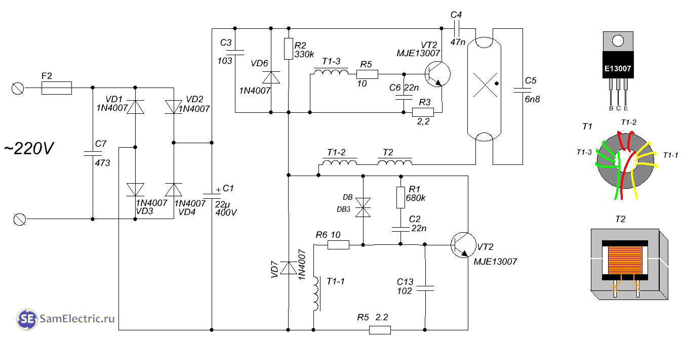
2. Diagram of an energy-saving lamp with a power of about 100 W. Option 2.

3. Diagram of a 20 W energy saving lamp.
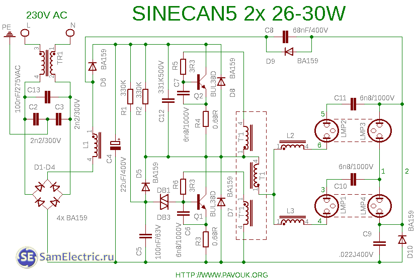
4. Sinecan5 circuit for 2 bulbs or lamps.
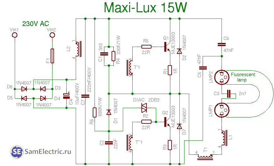
5. Maxilux 15w circuit

6. Osram 21w circuit

7. Eurolite 23w circuit
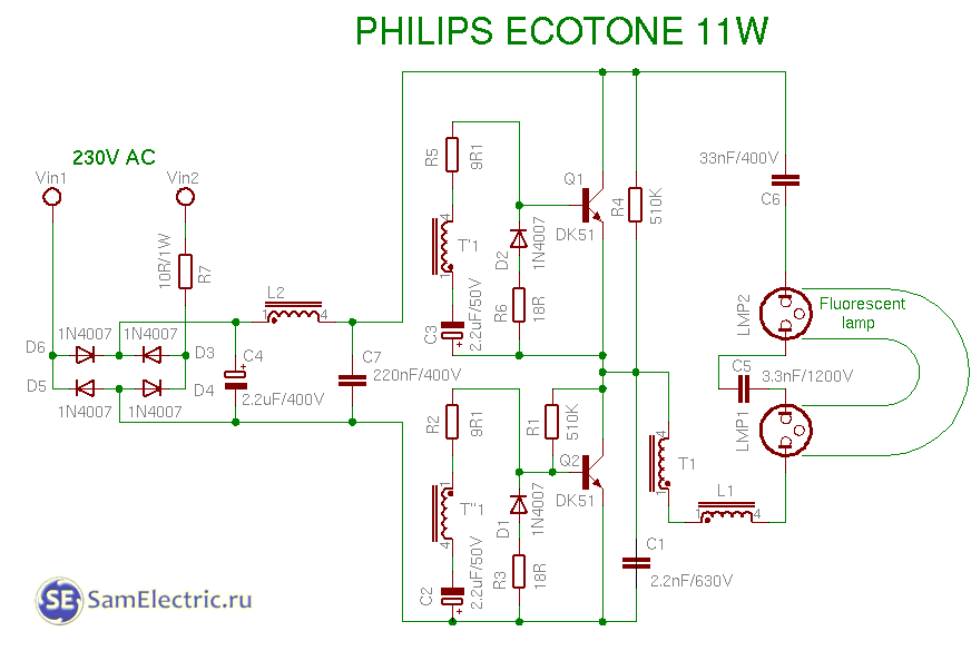
8. Philips 11w circuit
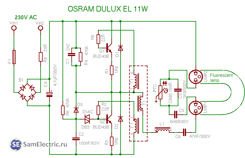
9. Osram 11w circuit
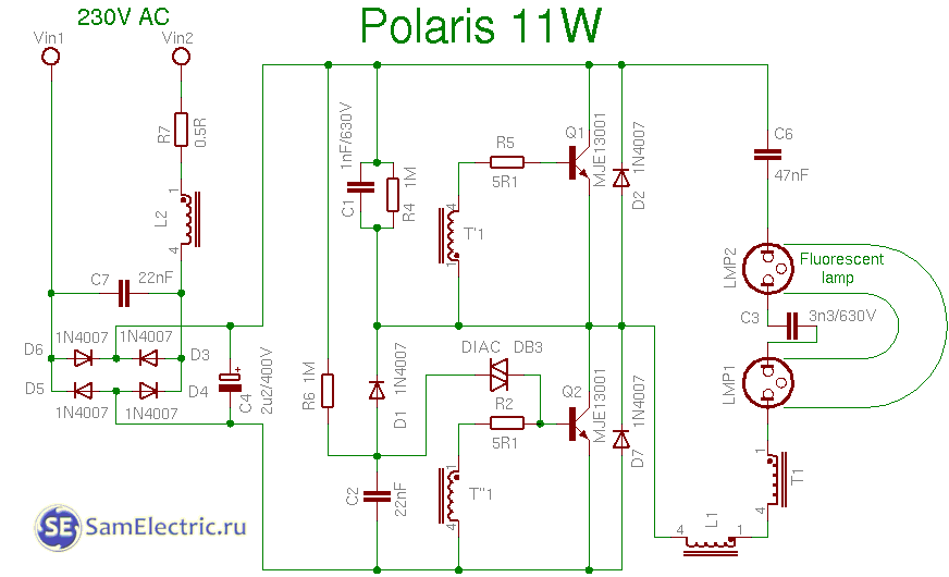
10. Polaris 11w circuit
![]()
11. Luxtek 8w circuit

12. Isotronic 11w circuit
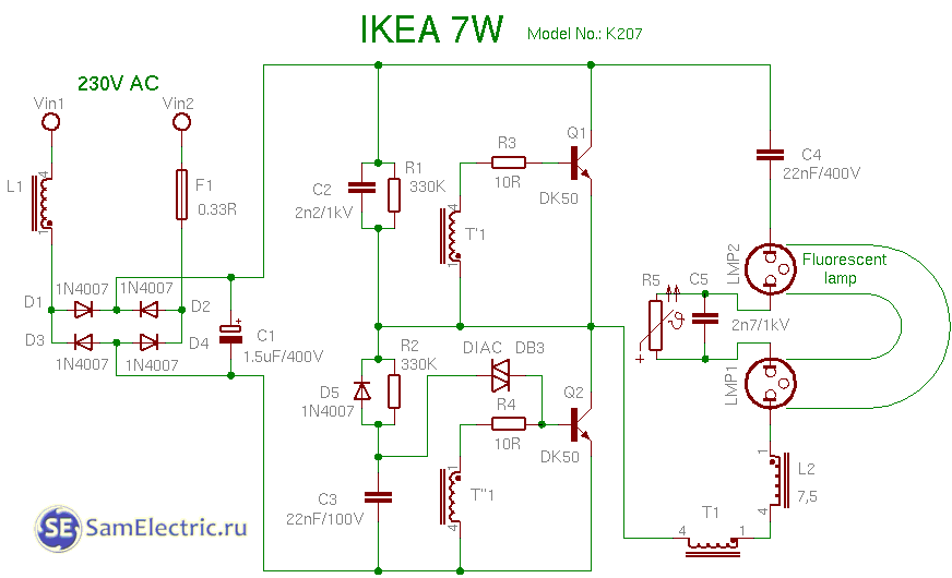
13. Ikea 7w diagram

14. Luxar 11w circuit

15. Maway 11w circuit
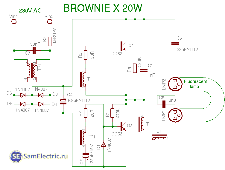
16. Scheme browniex 20w
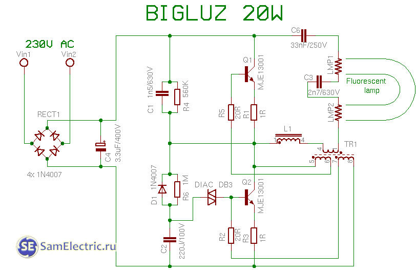
17. Bigluz 20w circuit
Here is a selection of schemes.
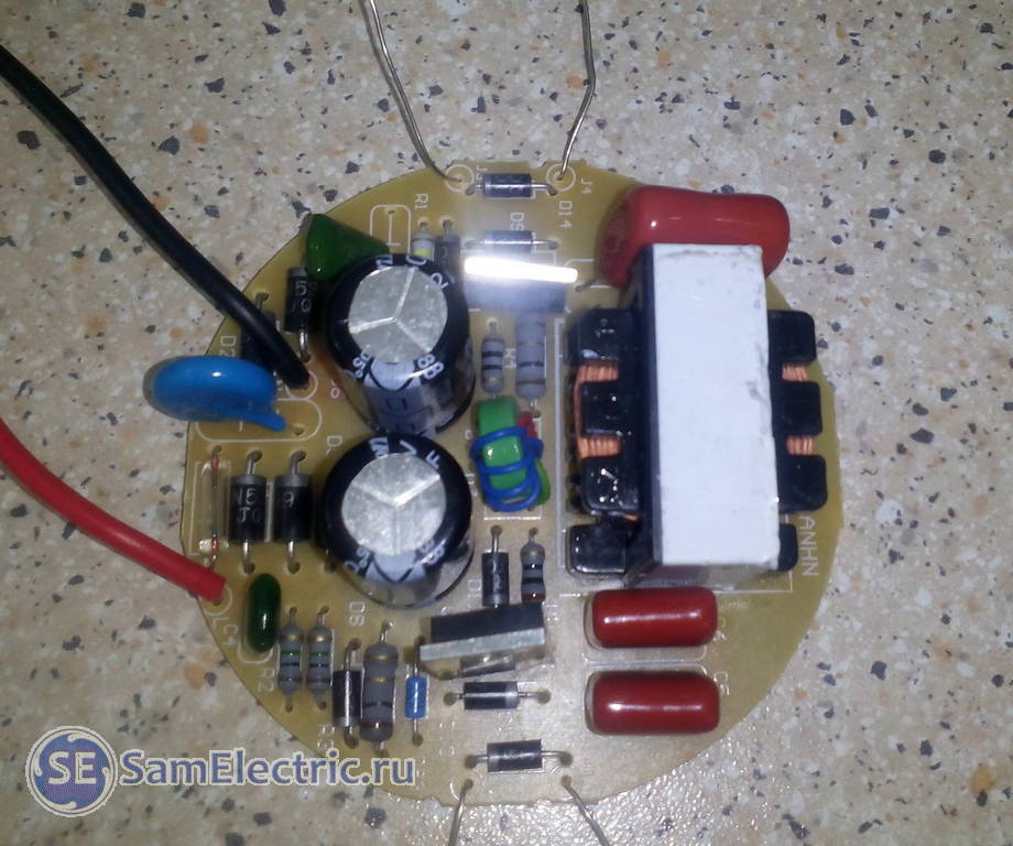
Update dated February 27, 2016
I am publishing a diagram and photo from a reader named Ikrom from sunny Tashkent. See his question and my answer in the comments for this date.
Lamp diagram. The + and - signs on the terminals of the diode bridge D1-D4 are swapped.
Download reference data for transistors for fluorescent lamps
As in the related article on lamp repair, I am posting files on the topic. Everything can be downloaded for free and freely. Enjoy it and write reviews and thanks in the comments.
Where can I buy
For those who are seriously involved in repairs, I provide, as an example, links to transistors for repairing lamps on Ali Express. Of course, whoever doesn’t want to wait a month and needs urgent and one-time repairs is better to purchase these transistors on the radio market.
- MJE13001— batch of 50 pieces, ruble-piece
- MJE13003— 20 pieces, 3 rubles/piece
- MJE13005— 10 pieces, 12 rubles each.
- MJE13007— 10 pieces, 12 rubles each.
- MJE13009— 10 pieces, 19 rubles each.
In conclusion, I would like to say that energy-saving lamp circuits are constantly being improved and changed, so not everything is listed on this page.
Video
Below is an example of an energy-saving repair:
Tired of it? Maybe this will be interesting:
Continuation of the article:Let me remind you, for those who want to do CFL repair:.
 (1 ratings, on average: 5,00 out of 5)

