Indicator with sound signal, for FOREX. Sound indicator. Scheme, description
The low-voltage sound indicator circuit (Fig. 4.12) is designed to improve the safety of driving a car at night. This device prevents the driver from falling asleep while driving. The indicator together with the battery is made on a single-sided printed circuit board in the form of a bracket (Fig. 4.13), which allows you to turn on the SA1 microswitch and attach it behind the ear.
When the head is tilted deeply (at the moment of falling asleep), the contacts of the tilt sensor F1 will close and the indicator will turn on - a loud signal will instantly wake up the driver.
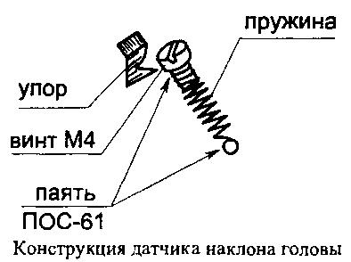
Of course, the reliability of the device will largely depend on the design of the F1 sensor. Having tried various designs head tilt sensor, I chose the simplest one - it can be easily done without the use of machines. It consists of a spring from a ballpoint pen, a brass screw M4x5 and a contact stop (Fig. 4.14). The screw is inserted into the spring and soldered (using flux or an aspirin tablet). The second end of the spring is shortened and attached to the board.
The indicator is operational when the supply voltage changes within the range from 0.7 to 2 V and consumes a current of no more than 5 mA.
The device circuit is a self-oscillator using transistors of different structures with direct coupling. The use of a piezo emitter makes it possible to make the indicator small-sized and lightweight. To obtain sufficient sound volume, coil L1 is connected in parallel with the piezo emitter. It, together with the internal capacitance HF1, forms a resonant circuit. This allows, due to resonant oscillations, to increase the operating voltage on the piezo emitter, which will significantly exceed the supply voltage.
Piezo emitters different types have the meaning of their own sound resonant frequency, located within 2...8 kHz. Therefore, when replacing the type of piezo emitter for each specific case can be picked up best combination circuit parameters (to obtain maximum volume with minimum current consumption).
The sound frequency can be changed by capacitor C1 or by changing the number of turns of coil L1, which, of course, is less convenient. Coil L1 contains 600 turns of PEV-0.08 wire (0.1 or 0.12 mm), wound on two rings of standard size K10x6x3 mm made of 700NM1 (or 1000NN) ferrite glued together with BF-2 (“Moment”) glue. Microswitch SA1 can be used type PD-9-2. Battery G1 type РЦ53М or similar. Resistors and capacitors are suitable for any type; transistors KT315G can be replaced with KT312V, KT3102E, and transistor KT361V with KT3107.
The highest sound volume will be when the frequency of the self-oscillator coincides with the natural resonant frequency of the piezo emitter. The sound indicator can find other applications, for example in children's toys.
Many traders have a negative attitude towards intraday trading, and when you listen to the arguments of most critics, it becomes obvious that people do not understand the true reason for their failures, which lies in their reluctance to follow the market. Beginners assume that they can enter into transactions in a chaotic manner and ultimately make a profit.
In fact, systematic trading involves not only compliance with the rules at the time of entering into a transaction, its main strength lies in compliance with the sequence of transactions. Absolutely all incoming signals must be processed, only in this case the overall result from a series of orders will be positive.
I don’t want to say that many beginners are undisciplined; for example, very often they have to combine work and trading, or maybe some household chores need to be resolved.
In any case, monitoring price fluctuations often becomes difficult, so only indicators with sound signals. The main thing to remember is that a reliable intraday trade requires hours of waiting and only a few minutes of real action.
How indicators with sound signals work
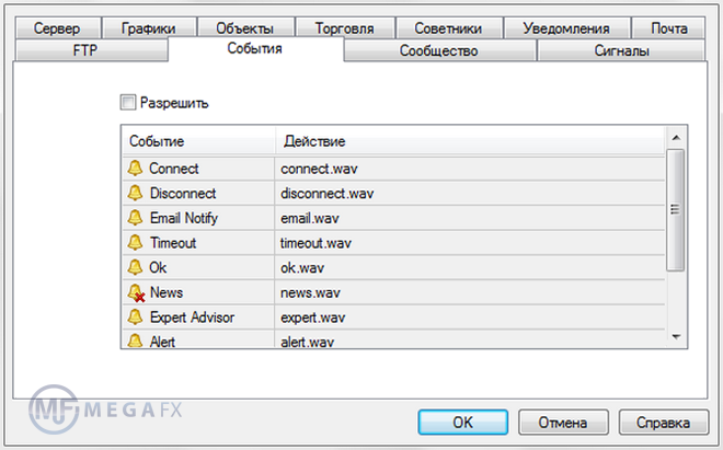
By default, special sound files have been added to the MetaTrader terminal, which are used to notify the trader about various events. You can find their names through the menu “Tools – Settings - Events tab”.
An alternative option is to go to the terminal directory using the following path: “MetaTraderSounds”.
The files located here have the extension “wav” and are used when writing indicators with sound signals. The programmer simply adds a certain condition to the code, upon reaching which the terminal will “give” an alert, and the terminal itself can be minimized. All that remains for the trader is to expand the working chart, assess the situation and make a decision.
It was not for nothing that I said “assess the situation”; the fact is that it is very difficult to completely automate really good intraday strategies. However, many scalpers trade with robots (the result of full automation is an advisor, logical?).
Of course, theoretically speaking, the inputs in a fully automated strategy can be automated, but problems often arise with the outputs (from requotes to the specifics of the instrument). Therefore, many scalpers prefer to take profits manually, i.e. Roughly speaking, mathematics is responsible for entering, and accumulated experience is responsible for exiting a transaction.
An example of using indicators with sound signals
Let me start with the fact that you can attach an “alert” to almost all indicators. If we distribute the entire set of sound indicators into groups, we get the following classification(if you try, you can identify subgroups, but for us this is not important now):
- They issue a signal for a breakout of the level (if the opening price of the candle is behind the level) - these are quite complex algorithms, since correct marking levels, problems arise even among traders, let alone the “machine”.
- They emit a sound signal when the oscillator reaches a critical level - these are the simplest assistants, built on standard indicators.
- They notify the trader of a trend reversal, which is most often determined using the MA.
In fact, this is a moving average, when the angle of which changes, the terminal emits sound signals. Unlike standard MA, when setting up AllAverages_2.5, the user can choose one of twenty options as a calculation formula, ranging from simple moving to integral linear regression.
Like many other indicators with audible signals, AllAverages can be used as a pre-emptive signal. For example, if trading strategy provides for purchases/sales along the trend on pullbacks, the trader no longer needs to constantly monitor the market, the algorithm will do all this work.
In this case, the sound signal will arrive after average prices begin to rise or fall (if this happens, we can talk about the end of the rollback), the user can only find a good moment to conclude a deal.
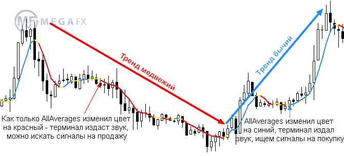
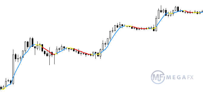
Speaking of signals, you can see on the chart that a unique color is assigned not only to the main directions of price movement (red - bearish, blue - bullish), there is also yellow, which indicates a trend reversal.
It is at the moment the yellow color appears that the indicator sound signal will beep for the first time. Therefore, even if a trader trades aggressively and opens positions immediately after the red flag reversal, he will still have some time to become familiar with the situation.
Depending on which formula is used to calculate average prices, the duration of the period colored yellow can vary significantly, and the result of the calculation greatly depends on the type of price (Open, Close, etc.).
I hope I answered the question “why do we need indicators with sound signals” when trading intraday. A dozen more examples could be given, but this is pointless, since the sound can be “screwed” to any expert without any problems. For almost all standard indicators (stochastic, RSI, etc.) audio versions are freely available.
Indicators with sound (with alert) are very convenient to use. So as not to look at the trading terminal all day.
The indicator calls the trader to the computer with a sound signal.
Indicators can be downloaded from the website.
https://www.mql5.com/ru
The site has a huge selection;
6,000+ trading robots and technical indicators for free!
This is one of the most best internet Forex resources. You can access the site from the metatrader.
If you do not find these indicators on this site, you can download them here at the end of the article.
For example; macd indicator.
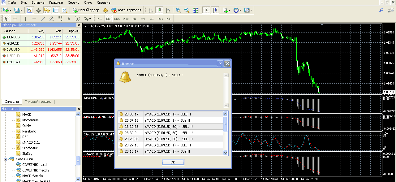
The indicator gives a sound signal, and in the metatrader's terminal a window pops up with parameters, which currency pair and for what time interval gave the signal.
Below is a 5-minute window with indicators macd (12,26,9) (9,21,7), the lowest smacd is the one with sound. This a large number of The macd indicator is included only to make it clear that they are the same. This is a regular indicator, only it has a sound when the fast line crosses the slow line. Naturally, it is better to remove them all. Leaving only one with sound. And if you want to change the parameters to 9,21,7, set the display at certain time intervals, this is done as in a regular indicator.
Please note that at an interval of 1 hour or more, the sound will always be made as soon as you move from other windows to this window, for almost an hour (as long as the indicator shows the intersection).
 Signal given by the MACD indicator
 The indicator is installed in the navigator window.
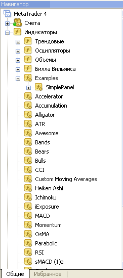 Navigator window
 The indicator sound can be changed. In this case it is set to alert.wav.
But by installing any other sound in the sounds folder, you can replace it.
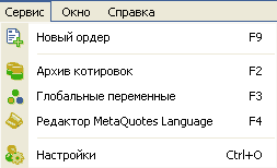 Service - settings
 By entering the service - settings, you change the sound made by the indicator.
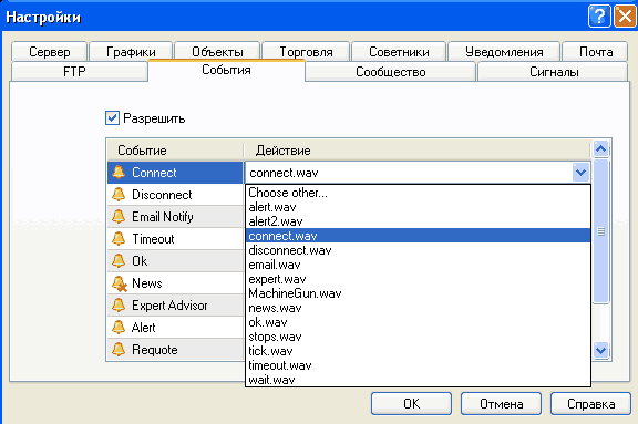 Selecting sound signals
 By clicking choose other, select any other from the sounds folder.
Any sounds can be downloaded from services specializing in sounds.
For example, an automatic queue. It will be heard throughout the whole house, but it gets tiresome quickly. http://www.vidiko.ru
This is what the signal sending block looks like.
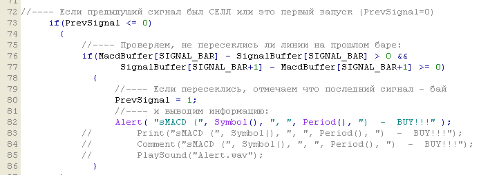 The program block responsible for sending a signal
 If you don’t find these indicators on the website mql5.com.ru
So, I'm posting them here.
These sites have become so huge that it is already very difficult to find the necessary information on them.
I only use "macd" with sound. It is best to use sound at intervals of 5 minutes and 1 minute. I’m setting up the rest of the indicators just like that, maybe it will be useful to someone. Indicators are compressed in zip.
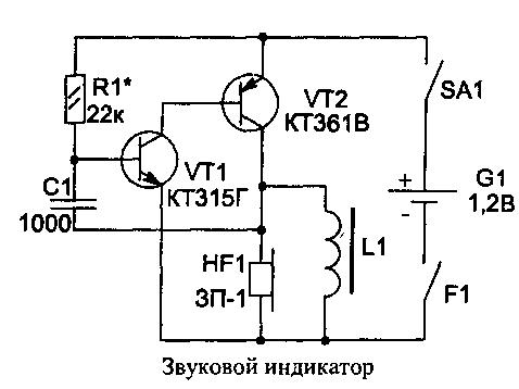
Rice. 4.12. Sound indicator
The low-voltage sound indicator circuit (Fig. 4.12) is designed to improve the safety of driving a car at night. This device prevents the driver from falling asleep while driving. The indicator together with the battery is made on a single-sided printed circuit board in the form of a bracket (Fig. 4.13), which allows you to turn on the SA1 microswitch and attach it behind the ear.
When the head is tilted deeply (at the moment of falling asleep), the contacts of the tilt sensor F1 will close and the indicator will turn on - a loud signal will instantly wake up the driver.
Of course, the reliability of the device will largely depend on the design of the F1 sensor. Having tried various designs of the head tilt sensor, I chose the simplest one - it can be easily made without the use of machines. It consists of a spring from a ballpoint pen, a brass screw M4x5 and a contact stop (Fig. 4.14). The screw is inserted into the spring and soldered (using flux or an aspirin tablet). The second end of the spring is shortened and attached to the board.
The indicator is operational when the supply voltage changes within the range from 0.7 to 2 V and consumes a current of no more than 5 mA.
The device circuit is a self-oscillator using transistors of different structures with direct coupling. The use of a piezo emitter makes it possible to make the indicator small-sized and lightweight. To obtain sufficient sound volume, coil L1 is connected in parallel with the piezo emitter. It, together with the internal capacitance HF1, forms a resonant circuit. This allows, due to resonant oscillations, to increase the operating voltage on the piezoelectric emitter, which will significantly exceed the supply voltage.
Rice. 4.13. Topology printed circuit board and arrangement of elements: The piezo emitter HF1 is fixed above the board elements by soldering to the contact pads
Piezo emitters of different types have values of their own sound resonant frequency that are in the range of 2...8 kHz. Therefore, when changing the type of piezo emitter for each specific case, you can select the best combination of circuit parameters (to obtain maximum volume with minimum current consumption).
Rice. 4.14. Head tilt sensor design
The sound frequency can be changed by capacitor C1 or by changing the number of turns of coil L1, which, of course, is less convenient. Coil L1 contains 600 turns of PEV-0.08 wire (0.1 or 0.12 mm), wound on two rings of standard size K10x6x3 mm made of 700NM1 (or 1000NN) ferrite glued together with BF-2 (“Moment”) glue. Microswitch SA1 can be used type PD-9-2. Battery G1 type РЦ53М or similar. Resistors and capacitors are suitable for any type; transistors KT315G can be replaced with KT312V, KT3102E, and transistor KT361V with KT3107.
The highest sound volume will be when the frequency of the self-oscillator coincides with the natural resonant frequency of the piezo emitter. The sound indicator can find other applications, for example in children's toys.
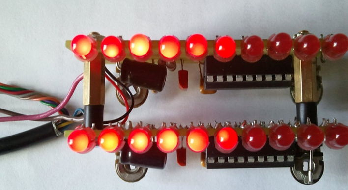
Determining the signal level on indicator LEDs is necessary to solve several problems (current and voltage indicators, phase changes), but most often such a circuit is used specifically to display the sound level.
In modern electronics, indicator LEDs have partly given way to devices based on LCDs and LED matrices. But a circuit of this type not only clearly shows the signal level, it is also easy to implement and quite visual.
What to assemble an LED level indicator from?
Analog-to-digital converters (ADC) LM3914-16 can be taken as a basis. These chips are capable of driving at least 10 diodes, and with the addition of new chips, the number of light bulbs can increase almost indefinitely. The indicator can have any color, and it is better to think about the design of the case in advance so that it does not become a surprise later.
LM3914 has a linear scale, which can also be used to measure voltage, and 15 and 16 have a logarithmic scale, but the pinout of the microcircuits is no different.
In this case, LEDs can be of any kind, imported or domestic, the main thing is that they are suitable for the task at hand. For example, you can use the simplest AL307 diodes, but you can also use more complex ones.
Calculation of the indicator scheme
Composing this device does not require any special skills. Calculation of current and voltage indicators can be done in any program, like a drawing.
One of the “legs” (9) of the microcircuit is connected to the positive voltage input. This way the LEDs will be controlled as a single column. In order to be able to independently regulate modes when changing phases, the circuit must include a switch, but it can easily do without it if this option is not needed.
The current passing through the LEDs for a given voltage and phase can be calculated as follows:
R – resistance on legs 7 and 8
For a current of 1 mA R=12.5 / 0.001 A = 12.5 kOhm.
And for a current of 20mA R=625 Ohm.
The introduction of a trimming resistor will make it possible to adjust the brightness of the glow; if there is no such need, you can install a regular one. The ratings for them will be 10 kOhm and 1 kOhm, respectively.
Final circuit LED indicator the level will be approximately this.
It is ideal for a mono signal, but for stereo you will have to create another one for the second channel. They can be combined through regular network cable taking into account the phase. An excellent option is to make two identical circuits made in different colors to demonstrate the level of each channel. Devices can also change their color range, but this implementation will be somewhat more complicated.
The value of C3 can be equal to 1 µF, provided that R4 = 100 kOhm. The R2 rating can be selected from the range of 47-100 kOhm.
This circuit uses a KT 315 transistor, but it can be replaced with any other one with suitable parameters (signal phase, current, voltage phase, p-n junction).
Tip: All the necessary elements can be purchased at the radio market or in a store; it is worth considering that LM3915-16 chips are slightly more expensive than LM3914. A less expensive option is to desolder components from existing boards.
The end result will be something like this:
Assembling a signal level indicator on your own is a completely solvable task. The main thing is to find what the circuit will be made of, and then spend a little time checking and debugging the device.
 (1 ratings, on average: 5,00 out of 5)

